EP0801885A1 - Guidage par rapport à ligne de récolte basé sur la vision - Google Patents
Guidage par rapport à ligne de récolte basé sur la vision Download PDFInfo
- Publication number
- EP0801885A1 EP0801885A1 EP97201110A EP97201110A EP0801885A1 EP 0801885 A1 EP0801885 A1 EP 0801885A1 EP 97201110 A EP97201110 A EP 97201110A EP 97201110 A EP97201110 A EP 97201110A EP 0801885 A1 EP0801885 A1 EP 0801885A1
- Authority
- EP
- European Patent Office
- Prior art keywords
- harvester
- pixel
- line
- steering
- vote counts
- Prior art date
- Legal status (The legal status is an assumption and is not a legal conclusion. Google has not performed a legal analysis and makes no representation as to the accuracy of the status listed.)
- Granted
Links
Images


Classifications
-
- A—HUMAN NECESSITIES
- A01—AGRICULTURE; FORESTRY; ANIMAL HUSBANDRY; HUNTING; TRAPPING; FISHING
- A01D—HARVESTING; MOWING
- A01D41/00—Combines, i.e. harvesters or mowers combined with threshing devices
- A01D41/12—Details of combines
- A01D41/127—Control or measuring arrangements specially adapted for combines
- A01D41/1278—Control or measuring arrangements specially adapted for combines for automatic steering
-
- A—HUMAN NECESSITIES
- A01—AGRICULTURE; FORESTRY; ANIMAL HUSBANDRY; HUNTING; TRAPPING; FISHING
- A01B—SOIL WORKING IN AGRICULTURE OR FORESTRY; PARTS, DETAILS, OR ACCESSORIES OF AGRICULTURAL MACHINES OR IMPLEMENTS, IN GENERAL
- A01B69/00—Steering of agricultural machines or implements; Guiding agricultural machines or implements on a desired track
- A01B69/001—Steering by means of optical assistance, e.g. television cameras
-
- G—PHYSICS
- G06—COMPUTING OR CALCULATING; COUNTING
- G06V—IMAGE OR VIDEO RECOGNITION OR UNDERSTANDING
- G06V20/00—Scenes; Scene-specific elements
- G06V20/50—Context or environment of the image
- G06V20/56—Context or environment of the image exterior to a vehicle by using sensors mounted on the vehicle
Definitions
- the present invention relates to agricultural machines and more particularly to self-propelled crop harvesting machines which, as part of the harvesting process, cut the crop or the plants on which the crop was grown.
- the invention provides an automatic steering control capable of determining the crop line between cut and uncut crop and steering the harvesting machine along the crop line as it traverses a field.
- Apparatus that can be utilized for detecting the crop line can be divided into two categories: range-based methods which attempt to detect the height difference between the cut and uncut crop; and vision-based methods which attempt to detect appearance differences between the crop on the cut and uncut side of the crop line.
- Range-based methods can include a scanning laser range-finder, a laser light striper, a stereo camera system, and an optical flow method.
- Vision based methods can include a feature tracking technique and segmentation on the basis of texture, intensity, and colour.
- Light striping systems have two components: a light source, and a camera tuned to detect only the frequencies emitted by the light source.
- a laser beam is sent through a cylindrical lens which spreads the linear beam into a plane. This plane intersects the scene in an illuminated line. Distances to all the points on the line can then be estimated by triangulation.
- the light striper has no moving parts, requires only minimal computational power, and is potentially inexpensive. However, since harvesters function outdoors, a prohibitively powerful laser would be needed to gather range information at the necessary distance (around 5 meters) in order to avoid being washed out by sunlight.
- the light striper system also has the disadvantage that it returns only a linear array of depths, so that only one point along the cut line can be detected at a time.
- Stereo cameras provide another possible alternative range-based approach to detecting the crop cut line, based on another triangulation-based method. Depth information is obtained by viewing the same object from two or more different viewpoints simultaneously, as with the human vision system. In this application, extremely precise depth information is not needed. Therefore two camera systems with relatively small baselines (between 15 and 60 cm) were investigated.
- the Storm stereo algorithm as defined in an article for the 1993 IEEE Conference on Computer Vision and Pattern Recognition, by Bill Ross, entitled "A Practical Stereo Vision System", was used to compute the correspondences. Although it was found that an alfalfa field contains sufficient texture to solve the correspondence problem, computational speed remains a major concern with stereo-based tracking.
- An alternative vision-based technique is defined as a window-based feature tracking method, as described in a 1991 Carnegie-Mellon Technical Report published by C. Tomasi and T. Kanade, entitled "Detection and Tracking of Point Features".
- a window-based feature tracking method Starting with an image of the crop cut line, a set of small (approximately 20 x 30 pixel) windows which overlapped the cut line boundary were selected by hand. These windows were then input as features to the algorithm, and then tracked from one image to the next. In this manner, it was possible to track the crop line across a sequence of twenty images. However, this method still requires that the initial feature windows be chosen along the crop line.
- It is an object of the present invention is to provide a vision-based method and apparatus for automatically steering a self-propelled harvester along a crop line.
- a method of steering an agricultural harvester along a crop line the harvester having control means for steering wheels to thereby steer the harvester, said method comprising:
- a self-propelled agricultural harvester comprising:
- the best fitting step function may be determined from calculations using the least-squared error criterion.
- calculation time may be reduced substantially.
- the vote counts may be normalized by dividing the developed sums by the number of scan lines. Steering reliability is enhanced by deriving steering preferences from a plurality of images.
- the steering signal then may be derived from averaged vote counts. The counts may have been time-weighted so that vote counts produced for more recent images have greater weight in determining the steering signal.
- Adjacent pixel locations can be assigned to bins, corresponding to distinct wheel positions, and the vote counts may be developed from the number of times the step position j n occurs at a pixel position assigned to a bin.
- the discriminant function may be percent intensity of a single spectral band or the intensity ratio between two spectral bands.
- the viewing means may comprise a colour video camera or a black-and-white camera having one or more associated band pass filters.
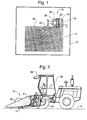
- Figure 1 illustrates a self-propelled agricultural harvester 10 in the process of cutting a crop in a field having a boundary 12.
- the uncut portion of the crop is indicated by the shaded area 14.
- the edge or division between the cut crop and the uncut crop in front of the harvester is generally referred to as the crop line and is designated by the reference numeral 16.
- the entire area of the field is not planted with crop.
- a headland having a width D is left unplanted at each end of the field and provides an area in which the harvester may turn around.
- the division between the headland and that portion of the field planted with crop is generally referred to as the "end of row” and is designated by the reference numeral 18.
- the invention is not limited to use in rectangular fields and the crop area to be cut may be irregular in shape.
- the harvester 10 may take many forms (combine, forage harvester, etc.) but experimentation was carried out using a model 2550 SpeedrowerTM sold commercially by New Holland North America Inc. This harvester is similar to the one shown in Figure 2. It cuts and conditions forage crops and discharges the harvested crop on the ground in either a consolidated windrow or a swath substantially as wide as the width of cut of the machine.
- the harvester has a cutter bar 13 which may be raised and lowered and which is carried slightly above ground level at the front of the harvester when cutting crop.
- a reel 20 sweeps the cut crop material into conditioning rolls 21 for further conditioning, and the conditioned crop is then discharged.
- the commercially available harvester was retrofitted with left and right electro-hydraulically controlled drive motors 46 and 48 ( Figure 3) for differentially and reversibly driving the front wheels 22, 24.
- the harvester as thus modified is steered by driving the front wheels at different relative speeds.
- the harvester 10 is provided with at least one video camera 30 (Figure 2) mounted on an arm extending outwardly from one side of the harvester.
- the camera was supported by an arm mounted near the top of the operator's cab 26 and extending to the left side of the harvester at a height of about 4 m above the ground.
- the camera is aimed about 5 m ahead of the harvester so as to capture an image of the landscape in front of the harvester.
- the camera is supported slightly inboard with respect to the left end of the harvester cutter bar so as to be directly over the crop line when the harvester is properly following the crop line. This avoids the necessity of computations relating to offset and permits the steering control algorithm to be based merely on steering the harvester to keep the crop line in the centre of the image.
- the cutter bar will slightly overlap the crop line. This overlap insures that narrow strips of uncut crop material are not left on the field.
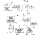
- the major hardware components of the system include at least one and possibly two video cameras 30, a video switch 32 if two cameras are used, a physical control computer 40, a video processing computer 42, left and right wheel drive motors 46, 48, an electrically controlled hydrostatic transmission 50, and conventional operator-actuated controls 78.
- Physical control computer 40 receives commands from controls 78 and, in response to these commands, generates speed and steering signals and implement control commands for controlling the cutter bar control mechanism 66.
- the harvester has been provided with left and right front wheel encoders 34 and 36 for purposes not relevant to the present invention.
- the physical control computer 40 may be a Motorola model MC68040 supported by the VxWorks real-time operating system.
- the video processing computer 42 may be a Sun Sparc 20 board running Unix and includes a digitizer 56 for digitizing video signals received from video switch 32. Computers 40 and 42 are interconnected by a serial Ethernet link 58.
- a Manual/Auto mode switch controls physical control computer 40 to respond to manual steering commands from controls 78 or automatic steering commands developed by video processing computer 42 as subsequently described.
- the computer 40 in turn, generates steering commands which are applied to the electrically controlled hydrostatic transmission 50.
- a steering command has a value which is the reciprocal of the radius of curvature of the commanded turn.
- a steering command may, for example, have one of 21 values between -0.1 (maximum left turn) and +0.1 (maximum right turn) with the value zero commanding steering straight ahead.
- the electrically controlled hydrostatic transmission 50 includes means for resolving the commands and generating two analog signals. These analog signals control the division of the total available hydraulic fluid flow between the wheel drive motors 46, 48 which in turn drive the front wheels at different speeds to cause the harvester to turn.
- a throttle control 76 governs the total available hydraulic fluid flow and thus sets the harvester speed.
- the camera 30 is preferably a colour video camera and in the development of the invention a RGB (red-green-blue) camera was used.
- the purpose of the camera is to form an electronic image of the landscape in front of the harvester and scan the image line-by-line and pixel-by-pixel to generate a signal containing information as to the spectral content of the image at each pixel position.
- a window may, for example, be 400 by 300 pixels but this size may be varied considerably.
- video processing computer 42 is to analyze the digitized video signal representing the scene within the field of view of the camera 30 and generate an indication of where the crop line is relative to the centre of the scene.
- Computer 42 is programmed to implement a discriminator and a segmenter.
- a colour segmentation algorithm combines two parts: a discriminator and a segmenter.
- the discriminator computes a function d(i,j) of individual pixels whereof the signals provide some information about whether that pixel is in the cut region or the uncut region.
- the segmenter uses the discriminant to produce a segmentation.
- S.D. standard deviation
- Experimentation was carried out using an RGB camera with the discriminant d(i,j) being the percentage intensity within a given spectral or the ratio between two spectral bands. The results are given in Table I.
- the filter data suggest that using a custom built camera sensitive to only a few narrow frequency bands may provide an advantage over an RGB camera.
- the discriminator computes from the digitized output signal of a camera a function d( i,j ) of individual pixels within a window or region of interest of say 400 by 300 pixels located at the centre of the video camera imaging screen.
- Figure 4D represents a plot of d( i,j ) for a portion of one scan line near the centre of a scan line i , the discriminant function being green percentage intensity. For each pixel position j the discriminator produces an output signal having a magnitude d( i,j ) related to the percentage green intensity at the pixel position. Because of the foliage on the uncut crop, the d( i,j ) are clustered about a first mean value m r ( Figure 4E) for uncut crop and about a second mean value m l for cut crop.
- Figure 4A shows a representable segmentation
- Figures 4B and 4C show some non-representable segmentations. This representation was chosen, not because it accurately characterizes all the images which might need to be segmented, but because it can be computed rapidly. Although images such as the ones in Figures 4B and 4C do occur, the chosen representation covers the vast majority of the images which appear in a harvesting operation.
- Figure 4E suggests a step function defined by three parameters: j n , the j coordinate of the discontinuity; m l , the mean value of the step function to the left of the discontinuity; and m r , the mean value of the step function to the right of the discontinuity. Finding the best segmentation is thus a matter of finding the best fit step function (lowest least-squared error) to d(i,j) along a given scan line.
- the segmenter may determine j n according to the following algorithm:
- the bulk of the computing time for this algorithm comes from computing m l , m r , and the error e.
- Computing the means and errors for the first j d takes order (j max -j min ) time.
- it requires only a small constant number of operations to recompute m l , m r , and error e for subsequent values of j d .
- the end result is that the entire algorithm requires only order (j max -j min ) time to find the best fit step function for a given scan line.
- a cycle time of roughly 4 Hz can be achieved for the entire system using the algorithm derived below.
- j d is defined as the right-most column or pixel to the left of the discontinuity and the column numbers vary from 0 to j max , then m l , m r and the error e may be calculated as functions of j d , these terms being defined for j d from 0 to j max -1.
- Equation 5 is then used to calculate the error at j d +1.
- the calculation may be accomplished with even fewer steps if some monotonic 1-to-1 function of error ( j d ) is computed rather than error ( j d ) .
- f(j d ) [ e ( j d ) ⁇ ( j max + 1)] 2 saves a square root and a division operation at each step.
- FIGS 5A and 5B illustrate a program routine executed by video processing computer 42 to generate a steering command from the digitized video signals obtained by scanning electronic images formed on the screen of camera 30 as the camera views the landscape in front of the harvester.
- Step 100 computes and saves the discriminant value d(i,j) for one pixel j according to the discriminant function being used, for example the ratio red/green.
- Step 101 determines if this is the last pixel (i,j) to be examined in the current scan line i and if it is not the last pixel step 100 is executed again to develop and save a discriminant value d( i , j +1) for the next pixel.
- steps 100 and 101 are repeated 400 times to develop and save 400 values d( i, 1)-d( i,400 ) .
- the test at step 101 proves true and the routine advances to step 102 which computes a best fit step function for these values.
- the location of the step defines a pixel location j n which in turn represents the segmentation, that is, the location of the crop line between cut and uncut crop as determined from the current scan line i.
- the segmenter output signal produced at step 102 is a binary signal having a bit position corresponding to each pixel position j on a single scan line i and within the window of interest.
- the signal has in it a single 1-bit in the position corresponding to the computed step function pixel location j n .
- This bit represents a crop line tracker "vote" on the steering angle or direction in which the harvester should be steered so as to track the crop line and keep the crop line image at the centre of the window.
- the votes on the steering direction should be in the same bit position of each output signal when the harvester is tracking the crop line.
- An accumulator is provided for each pixel position and at step 103 the vote generated at step 102 is added into the accumulator which accumulates votes for boundary location j n .
- the segmenter produces one output signal or vote for each scan line i within the window or region of interest.
- Step 104 determines if the last scan line of the window has been processed. If the last scan line has not been processed, a return is made to step 100 and steps 100-103 are repeated to develop a vote on the steering direction for the next scan line.
- step 104 detects when all 100 scan lines of the image within the window have been processed and the program advances to step 105.
- the crop line tracker has developed, from one complete scan of the image, 100 votes on the steering direction, these votes being distributed among 400 vote accumulators.
- the electrical controls of hydrostatic transmission 50 ( Figure 3) are capable of controlling steering at only 21 different degrees of curvature. Therefore, the 400 pixel positions are divided into groups of adjacent positions and assigned to 21 bins. The accumulated vote counts for all pixel positions assigned to a given bin are then summed at step 105 to obtain 21 bin vote counts.
- the bin vote counts are normalized by dividing them by the number of scan lines (100) and the normalized vote counts are saved.
- the crop line tracker produces 21 normalized bin votes on the steering direction, each normalized vote having a value between 0.0 and 1.0 and the sum of the normalized votes being 1.
- the normalized bin votes are saved in memory for further processing as subsequently described.
- the size of the window image need not be 400 x 100 pixels and it is not necessary to process every pixel position of the image within the window.
- the processing of every third or fourth pixel may be eliminated to reduce signal processing time if the uncut crop is relatively uniform over the field and is easy to discriminate from the cut portion of the field.
- the normalized bin vote counts saved at step 106 as a result of scanning one image are time-decayed and averaged with the bin vote counts resulting from scans of previous images.
- the reason for this may be explained with reference to Figure 6 which illustrates a typical situation for the case of a poor crop. The figure is drawn for the case of more than 21 steering directions to more clearly demonstrate the smoothing function.
- graphs (a)-(d) represent the bin vote counts generated as a result of scanning four successive images, graph (a) being for the most recent image.
- Each vertical bar in a graph represents the vote count in one of the bins, that is, the accumulated vote count for one bin as developed by the crop line tracker at step 105 in Figure 5A and before the vote counts are normalized.
- the votes accumulated for each image have been time weighted by a factor as indicated to the left of each graph.
- the bin or steering direction referenced 220 has the highest vote sum hence if the votes derived from this image alone were considered, the harvester would be commanded to make a rather extreme turn to the left because this bin is separated from the "straight ahead" bin, represented by 0, by about 15 bins.
- the vote summations for the bins referenced 221, 222 and 223, respectively are the greatest hence if the vote summations for these images were acted on alone, the harvester would be commanded to steer gently to the right by slightly varying degrees.
- step 107 time weights or decays each of the 21 normalized bin vote counts resulting from the scans of the last n images.
- Step 108 averages the decayed normalized bin vote counts obtained at step 107 to generate a steering preference signal. From the foregoing description it is evident that the steering preference signal comprises 21 bins or values. The steering preference signal is then saved at step 109.
- step 110 checks a timer to see if 0.1 second has elapsed. Steering commands are generated at intervals of 0.1 sec. If step 110 determines that 0.1 second has not elapsed since generation of the last steering command, steps 107-109 are repeated. After 0.1 second the test at step 110 proves true and step 111 is executed. Step 111 examines each of the 21 bin totals saved at step 109 and determines which bin has the largest total. A steering command is then generated (step 112), the steering command having a 1-bit in the position corresponding to the position of the bin found to have the largest value.
- the steering commands produced at step 112 are transferred from computer 42 through computer 40 to the electrical controls of transmission 50 which decode the commands as described above to differentially drive the front wheels and thereby steer the harvester in the commanded direction.
- the invention described above is capable of acting as a "cruise control", relieving the operator of the responsibility of steering the harvester. It may be used in conjunction with an end of row detector which slows or stops the forward progress of the harvester and signals the operator to assume manual control to accomplish turning.
- the invention may also be incorporated into a fully automated control system which also controls turning, thereby eliminating the necessity for an operator on the harvester.
Landscapes
- Life Sciences & Earth Sciences (AREA)
- Engineering & Computer Science (AREA)
- Environmental Sciences (AREA)
- Mechanical Engineering (AREA)
- Soil Sciences (AREA)
- Physics & Mathematics (AREA)
- General Physics & Mathematics (AREA)
- Multimedia (AREA)
- Theoretical Computer Science (AREA)
- Guiding Agricultural Machines (AREA)
Applications Claiming Priority (2)
| Application Number | Priority Date | Filing Date | Title |
|---|---|---|---|
| US1623696P | 1996-04-19 | 1996-04-19 | |
| US16236 | 1998-01-30 |
Publications (2)
| Publication Number | Publication Date |
|---|---|
| EP0801885A1 true EP0801885A1 (fr) | 1997-10-22 |
| EP0801885B1 EP0801885B1 (fr) | 2002-01-09 |
Family
ID=21776080
Family Applications (1)
| Application Number | Title | Priority Date | Filing Date |
|---|---|---|---|
| EP97201110A Expired - Lifetime EP0801885B1 (fr) | 1996-04-19 | 1997-04-15 | Guidage par rapport à ligne de récolte basé sur la vision |
Country Status (3)
| Country | Link |
|---|---|
| US (1) | US5911669A (fr) |
| EP (1) | EP0801885B1 (fr) |
| DE (1) | DE69709482T2 (fr) |
Cited By (9)
| Publication number | Priority date | Publication date | Assignee | Title |
|---|---|---|---|---|
| EP0878121A1 (fr) * | 1997-05-13 | 1998-11-18 | CLAAS KGaA | Machine de récolte à direction automatique |
| EP0906720A1 (fr) * | 1997-10-04 | 1999-04-07 | CLAAS Selbstfahrende Erntemaschinen GmbH | Appareil et méthode pour la reconnaissance sans contact des limites de la zone de travail ou de sa taille correspondante |
| EP0975209A4 (fr) * | 1997-04-16 | 2000-05-31 | Univ Carnegie Mellon | Machine agricole de recolte commandee par robot |
| EP1112679A3 (fr) * | 1999-12-30 | 2001-10-31 | Claudio Ciani | Dispositif pour traiter des cultures en lignes |
| US6679338B1 (en) | 1999-07-20 | 2004-01-20 | Agriculture Guide Implement Systems Pty Ltd. | Locating system and method |
| FR2859873A1 (fr) * | 2003-09-22 | 2005-03-25 | Moreau Jean Ets | Procede de guidage d'un appareil agricole fonctionnant selon ce procede |
| EP1529428A1 (fr) | 2003-11-06 | 2005-05-11 | Deere & Company | Procédé et système pour la direction automatique d'une machine agricole |
| CN105251563A (zh) * | 2015-09-22 | 2016-01-20 | 中国矿业大学 | 一种齿辊式破碎机的自动调速控制系统及控制方法 |
| US20220400606A1 (en) * | 2021-06-18 | 2022-12-22 | Green Industry Innovators, L.L.C. | Landscaping equipment with included laser and methods of operation |
Families Citing this family (82)
| Publication number | Priority date | Publication date | Assignee | Title |
|---|---|---|---|---|
| DE29724569U1 (de) | 1997-06-25 | 2002-05-16 | Claas Selbstfahrende Erntemaschinen GmbH, 33428 Harsewinkel | Vorrichtung an Landmaschinen zur berührungslosen Abtastung von sich über dem Boden erstreckender Konturen |
| US6469628B1 (en) | 1998-03-23 | 2002-10-22 | Time Domain Corporation | System and method for using impulse radio technology in the farming field |
| US6540633B1 (en) * | 1998-09-25 | 2003-04-01 | Tuff Torq Corporation | Transmission for speed changing and steering of a vehicle |
| DE19853085B4 (de) * | 1998-11-18 | 2014-03-20 | Claas Selbstfahrende Erntemaschinen Gmbh | Verfahren zum Justieren einer an einer Feldmaschine befestigten Sensoreinheit sowie eine Justiereinrichtung und eine Feldmaschine |
| US7155056B2 (en) * | 2000-05-03 | 2006-12-26 | Eco-Dan A/S | Method of segmentation of a digital image and a method of controlling an implement |
| US6385515B1 (en) * | 2000-06-15 | 2002-05-07 | Case Corporation | Trajectory path planner for a vision guidance system |
| US6364027B1 (en) * | 2000-06-26 | 2002-04-02 | Donald Tvetene | Sod harvester |
| US6714662B1 (en) * | 2000-07-10 | 2004-03-30 | Case Corporation | Method and apparatus for determining the quality of an image of an agricultural field using a plurality of fuzzy logic input membership functions |
| US6721453B1 (en) * | 2000-07-10 | 2004-04-13 | The Board Of Trustees Of The University Of Illinois | Method and apparatus for processing an image of an agricultural field |
| DE10129136A1 (de) * | 2001-06-16 | 2002-12-19 | Deere & Co | Einrichtung zur selbsttätigen Lenkung eines landwirtschaftlichen Arbeitsfahrzeugs |
| US6615570B2 (en) * | 2001-06-28 | 2003-09-09 | Deere & Company | Header position control with forward contour prediction |
| DE10204702A1 (de) * | 2002-02-05 | 2003-08-14 | Claas Selbstfahr Erntemasch | Ortungssystem an selbstfahrenden landwirtschaftlichen Arbeitsmaschinen |
| US6943824B2 (en) * | 2002-03-13 | 2005-09-13 | Deere & Company | Image processing spout control system |
| JP3950358B2 (ja) * | 2002-04-24 | 2007-08-01 | 株式会社 神崎高級工機製作所 | 作業車の操向装置 |
| DE10227484A1 (de) * | 2002-06-19 | 2004-02-26 | Claas Selbstfahrende Erntemaschinen Gmbh | Vorrichtung und Verfahren zur Lagesteuerung eines Erntegutaufnahmegerätes landwirtschaftlicher Erntemaschinen |
| US6738695B1 (en) | 2002-12-16 | 2004-05-18 | Caterpillar Inc | System and method for initializing autoguidance for a mobile machine |
| CA2427416C (fr) * | 2003-05-01 | 2010-11-16 | 101039130 Saskatchewan Ltd. | Dispositif de direction pour outils remorques |
| US20060185340A1 (en) * | 2003-05-19 | 2006-08-24 | Eyre Robert J | Cutting and threshing header for harvesting machine |
| DE10328395B4 (de) * | 2003-06-18 | 2010-11-11 | Gebr. Pöttinger GmbH | Verfahren zur Steuerung einer Landmaschine |
| US7916898B2 (en) * | 2003-09-15 | 2011-03-29 | Deere & Company | Method and system for identifying an edge of a crop |
| US7412905B1 (en) | 2004-05-31 | 2008-08-19 | Richard Anthony Bishel | Paddle sensor |
| DE102004059543A1 (de) * | 2004-12-09 | 2006-06-29 | Claas Selbstfahrende Erntemaschinen Gmbh | Landwirtschaftliche Arbeitsmaschine |
| DE102005005557C5 (de) * | 2005-02-07 | 2019-03-14 | Pöttinger Landtechnik Gmbh | Vorrichtung zur Steuerung und/oder Regelung einer Landmaschine mittels einer Bilderfassungs- und -verarbeitungseinrichtung |
| US20060271262A1 (en) * | 2005-05-24 | 2006-11-30 | Mclain Harry P Iii | Wireless agricultural network |
| US8185275B2 (en) * | 2005-07-01 | 2012-05-22 | Deere & Company | System for vehicular guidance with respect to harvested crop |
| US7792622B2 (en) * | 2005-07-01 | 2010-09-07 | Deere & Company | Method and system for vehicular guidance using a crop image |
| US7684916B2 (en) * | 2005-07-01 | 2010-03-23 | Deere & Company | Method and system for vehicular guidance using a crop image |
| US7404355B2 (en) * | 2006-01-31 | 2008-07-29 | Deere & Company | Tractor and baler combination with automatic baling and tractor halt control |
| US8121345B2 (en) * | 2006-05-18 | 2012-02-21 | Applied Perception, Inc. | Vision guidance system and method for identifying the position of crop rows in a field |
| US7865285B2 (en) * | 2006-12-27 | 2011-01-04 | Caterpillar Inc | Machine control system and method |
| US7740083B2 (en) * | 2007-07-23 | 2010-06-22 | Trebro Holding Co., Inc. | Sod harvesting apparatus |
| US8132700B2 (en) * | 2007-08-02 | 2012-03-13 | Trek Bicycle Corporation | Bicycle accessory mounting system |
| US8478493B2 (en) * | 2008-09-11 | 2013-07-02 | Deere & Company | High integrity perception program |
| US8229618B2 (en) * | 2008-09-11 | 2012-07-24 | Deere & Company | Leader-follower fully autonomous vehicle with operator on side |
| US8392065B2 (en) * | 2008-09-11 | 2013-03-05 | Deere & Company | Leader-follower semi-autonomous vehicle with operator on side |
| US8195358B2 (en) * | 2008-09-11 | 2012-06-05 | Deere & Company | Multi-vehicle high integrity perception |
| US8989972B2 (en) | 2008-09-11 | 2015-03-24 | Deere & Company | Leader-follower fully-autonomous vehicle with operator on side |
| US8224500B2 (en) | 2008-09-11 | 2012-07-17 | Deere & Company | Distributed knowledge base program for vehicular localization and work-site management |
| US8818567B2 (en) * | 2008-09-11 | 2014-08-26 | Deere & Company | High integrity perception for machine localization and safeguarding |
| US9026315B2 (en) | 2010-10-13 | 2015-05-05 | Deere & Company | Apparatus for machine coordination which maintains line-of-site contact |
| US9235214B2 (en) * | 2008-09-11 | 2016-01-12 | Deere & Company | Distributed knowledge base method for vehicular localization and work-site management |
| US9188980B2 (en) * | 2008-09-11 | 2015-11-17 | Deere & Company | Vehicle with high integrity perception system |
| US8195342B2 (en) * | 2008-09-11 | 2012-06-05 | Deere & Company | Distributed knowledge base for vehicular localization and work-site management |
| US20100063652A1 (en) * | 2008-09-11 | 2010-03-11 | Noel Wayne Anderson | Garment for Use Near Autonomous Machines |
| US8233709B2 (en) * | 2009-03-06 | 2012-07-31 | Sony Corporation | Color effects for compressed digital video |
| US8306663B2 (en) * | 2009-05-13 | 2012-11-06 | Robotic Harvesting LLC | Robot with 3D grasping capability |
| EP3118815B1 (fr) * | 2009-07-01 | 2018-03-07 | MTD Products Inc. | Segmentation visuelle de gazon |
| US8396597B2 (en) * | 2009-08-18 | 2013-03-12 | Deere & Company | Distributed robotic guidance |
| US20110046784A1 (en) * | 2009-08-18 | 2011-02-24 | Noel Wayne Anderson | Asymmetric stereo vision system |
| US8224516B2 (en) | 2009-12-17 | 2012-07-17 | Deere & Company | System and method for area coverage using sector decomposition |
| US8635015B2 (en) | 2009-12-17 | 2014-01-21 | Deere & Company | Enhanced visual landmark for localization |
| US20110153338A1 (en) * | 2009-12-17 | 2011-06-23 | Noel Wayne Anderson | System and method for deploying portable landmarks |
| US9587491B2 (en) * | 2010-09-22 | 2017-03-07 | Joy Mm Delaware, Inc. | Guidance system for a mining machine |
| JP5626056B2 (ja) * | 2011-03-18 | 2014-11-19 | 富士通株式会社 | 農作物画像処理プログラム、農作物画像処理方法及び農作物画像処理装置 |
| KR101448248B1 (ko) * | 2011-08-03 | 2014-10-07 | 엘지전자 주식회사 | 잔디 깎기용 이동로봇 및 이의 제어방법 |
| US8857137B2 (en) * | 2011-11-17 | 2014-10-14 | Tzvi Avnery | Robotic lawn mower for cutting around conveyance member |
| US9271446B2 (en) | 2012-06-28 | 2016-03-01 | Forage Innovations B.V. | Self-aligning apparatus and methods for gathering bales |
| WO2014105927A1 (fr) * | 2012-12-28 | 2014-07-03 | Agco Corporation | Utilisation d'une rampe virtuelle pour diriger un équipement agricole le long du bord de zones travaillées/non travaillées |
| WO2014105928A1 (fr) * | 2012-12-28 | 2014-07-03 | Agco Corporation | Procédé et applications de système de coordonnées locales sur la base d'un flux de données optiques au moyen de caméras vidéo |
| EP2798928B1 (fr) * | 2013-04-29 | 2024-02-07 | CLAAS E-Systems GmbH | Système d'operation et procédé permettant de faire fonctionner un système de guidage automatique d'un véhicule agricole |
| US9565848B2 (en) * | 2013-09-13 | 2017-02-14 | Palo Alto Research Center Incorporated | Unwanted plant removal system |
| US9609859B2 (en) | 2013-09-13 | 2017-04-04 | Palo Alto Research Center Incorporated | Unwanted plant removal system having a stabilization system |
| US9609858B2 (en) | 2013-09-13 | 2017-04-04 | Palo Alto Research Center Incorporated | Unwanted plant removal system having variable optics |
| WO2015035450A1 (fr) * | 2013-09-13 | 2015-03-19 | Queensland University Of Technology | Guidage reposant sur la vision en agriculture de grandes superficies |
| US9642306B1 (en) * | 2013-09-18 | 2017-05-09 | Lon Owen Crosby | Offset, drive-assisted header for a grain harvester |
| DE102014105820A1 (de) * | 2014-04-25 | 2015-10-29 | Usines Claas France S.A.S. | Kombination aus einem Zugfahrzeug und einer davon gezogenen Erntemaschine |
| US9585309B2 (en) * | 2015-07-14 | 2017-03-07 | Cnh Industrial America Llc | Header height control system for an agricultural harvester |
| JP6754594B2 (ja) * | 2016-03-23 | 2020-09-16 | 株式会社小松製作所 | モータグレーダ |
| US10051774B2 (en) | 2016-09-16 | 2018-08-21 | Cnh Industrial Canada, Ltd. | Common lift/lower ground entrance point |
| JP2018097526A (ja) * | 2016-12-12 | 2018-06-21 | 株式会社クボタ | 作業車 |
| WO2018107242A1 (fr) * | 2016-12-16 | 2018-06-21 | Commonwealth Scientific And Industrial Research Organisation | Dispositif de balayage de cultures |
| US9989835B1 (en) | 2017-02-09 | 2018-06-05 | Cnh Industrial America Llc | System and method for mounting a camera on a work vehicle |
| IT201700058505A1 (it) | 2017-05-30 | 2018-11-30 | Volta Robots S R L | Metodo di controllo di un mezzo di lavorazione del terreno sulla base di elaborazioni d'immagini e relativo sistema |
| RU2747303C2 (ru) * | 2018-04-09 | 2021-05-04 | Дир Энд Компани | Система для управления рабочим параметром уборочной жатки |
| US11170530B2 (en) * | 2018-07-11 | 2021-11-09 | Raven Industries, Inc. | Calibrating crop row computer vision system |
| WO2020105123A1 (fr) * | 2018-11-20 | 2020-05-28 | 本田技研工業株式会社 | Machine de travail autonome, procédé de commande de machine de travail autonome, et programme |
| EP3874925B1 (fr) * | 2018-11-20 | 2023-06-14 | Honda Motor Co., Ltd. | Machine de travail autonome, procédé de commande de machine de travail autonome et programme |
| DE102018220410A1 (de) * | 2018-11-28 | 2020-05-28 | Zf Friedrichshafen Ag | Selbsttätiges Lenken einer landwirtschaftlichen Maschine auf einer landwirtschaftlichen Fläche |
| JP7587503B2 (ja) * | 2018-12-29 | 2024-11-20 | 豊疆智能科技股▲ふん▼有限公司 | ハーベスター及びその自動運転方法 |
| DE102019204251A1 (de) * | 2019-03-27 | 2020-10-01 | Zf Friedrichshafen Ag | Verfahren und System zur Linienerfassung auf einer landwirtschaftlichen Nutzfläche |
| US11367279B1 (en) | 2019-04-19 | 2022-06-21 | David R. Wilmot | Sensors, sod harvester with the sensors and methods for steering or guiding sod harvesters |
| US12543620B2 (en) | 2023-11-10 | 2026-02-10 | Exel Industries | Navigation system for agricultural machine |
Citations (5)
| Publication number | Priority date | Publication date | Assignee | Title |
|---|---|---|---|---|
| US4077488A (en) * | 1976-06-15 | 1978-03-07 | Sperry Rand Corporation | Guidance assist system for agricultural machines |
| US4482960A (en) * | 1981-11-20 | 1984-11-13 | Diffracto Ltd. | Robot tractors |
| US4555725A (en) * | 1983-08-24 | 1985-11-26 | Deutz-Allis Corporation | Agricultural implement steering guidance system and method |
| DE3507570A1 (de) * | 1985-03-04 | 1986-09-04 | Willi Eisen GmbH, 3060 Stadthagen | Verfahren und vorrichtung zur automatischen lenkung eines fahrzeuges, insbesondere eines landwirtschaftlichen fahrzeuges, entlang eines in fahrtrichtung orientierten musters |
| US5509486A (en) * | 1994-08-12 | 1996-04-23 | Loral Corporation | Method of steering an agricultural vehicle |
Family Cites Families (3)
| Publication number | Priority date | Publication date | Assignee | Title |
|---|---|---|---|---|
| US4700301A (en) * | 1983-11-02 | 1987-10-13 | Dyke Howard L | Method of automatically steering agricultural type vehicles |
| KR100189345B1 (ko) * | 1990-09-24 | 1999-06-01 | 앙드레 코렌스 | 연속적 자율적인 초삭(草削)기 |
| US5442552A (en) * | 1993-03-16 | 1995-08-15 | The Regents Of The University Of California | Robotic cultivator |
-
1997
- 1997-04-15 EP EP97201110A patent/EP0801885B1/fr not_active Expired - Lifetime
- 1997-04-15 DE DE69709482T patent/DE69709482T2/de not_active Expired - Lifetime
- 1997-04-16 US US08/840,771 patent/US5911669A/en not_active Expired - Fee Related
Patent Citations (5)
| Publication number | Priority date | Publication date | Assignee | Title |
|---|---|---|---|---|
| US4077488A (en) * | 1976-06-15 | 1978-03-07 | Sperry Rand Corporation | Guidance assist system for agricultural machines |
| US4482960A (en) * | 1981-11-20 | 1984-11-13 | Diffracto Ltd. | Robot tractors |
| US4555725A (en) * | 1983-08-24 | 1985-11-26 | Deutz-Allis Corporation | Agricultural implement steering guidance system and method |
| DE3507570A1 (de) * | 1985-03-04 | 1986-09-04 | Willi Eisen GmbH, 3060 Stadthagen | Verfahren und vorrichtung zur automatischen lenkung eines fahrzeuges, insbesondere eines landwirtschaftlichen fahrzeuges, entlang eines in fahrtrichtung orientierten musters |
| US5509486A (en) * | 1994-08-12 | 1996-04-23 | Loral Corporation | Method of steering an agricultural vehicle |
Non-Patent Citations (2)
| Title |
|---|
| REID & SEARCY: "an algorithm for separating guidance information from row crop images", TRANSACTIONS OF THE ASAE, vol. 31, no. 5, November 1988 (1988-11-01), MICHIGAN, pages 1624 - 1632, XP002036616 * |
| SEARCY REID: "VISION-BASED GUIDANCE OF AN AGRICULTURAL TRACTOR", 06-1986, XP002036617 * |
Cited By (11)
| Publication number | Priority date | Publication date | Assignee | Title |
|---|---|---|---|---|
| EP0975209A4 (fr) * | 1997-04-16 | 2000-05-31 | Univ Carnegie Mellon | Machine agricole de recolte commandee par robot |
| EP0878121A1 (fr) * | 1997-05-13 | 1998-11-18 | CLAAS KGaA | Machine de récolte à direction automatique |
| EP0906720A1 (fr) * | 1997-10-04 | 1999-04-07 | CLAAS Selbstfahrende Erntemaschinen GmbH | Appareil et méthode pour la reconnaissance sans contact des limites de la zone de travail ou de sa taille correspondante |
| US6679338B1 (en) | 1999-07-20 | 2004-01-20 | Agriculture Guide Implement Systems Pty Ltd. | Locating system and method |
| EP1112679A3 (fr) * | 1999-12-30 | 2001-10-31 | Claudio Ciani | Dispositif pour traiter des cultures en lignes |
| FR2859873A1 (fr) * | 2003-09-22 | 2005-03-25 | Moreau Jean Ets | Procede de guidage d'un appareil agricole fonctionnant selon ce procede |
| EP1529428A1 (fr) | 2003-11-06 | 2005-05-11 | Deere & Company | Procédé et système pour la direction automatique d'une machine agricole |
| US7400957B2 (en) | 2003-11-06 | 2008-07-15 | Deere & Company | Process and steering system for the automatic steering of an agricultural vehicle |
| RU2361381C2 (ru) * | 2003-11-06 | 2009-07-20 | Дир Энд Компани | Способ и система автоматического управления сельскохозяйственной машиной, уборочная машина и машина для обработки почвы |
| CN105251563A (zh) * | 2015-09-22 | 2016-01-20 | 中国矿业大学 | 一种齿辊式破碎机的自动调速控制系统及控制方法 |
| US20220400606A1 (en) * | 2021-06-18 | 2022-12-22 | Green Industry Innovators, L.L.C. | Landscaping equipment with included laser and methods of operation |
Also Published As
| Publication number | Publication date |
|---|---|
| DE69709482D1 (de) | 2002-02-14 |
| EP0801885B1 (fr) | 2002-01-09 |
| DE69709482T2 (de) | 2002-11-07 |
| US5911669A (en) | 1999-06-15 |
Similar Documents
| Publication | Publication Date | Title |
|---|---|---|
| EP0801885B1 (fr) | Guidage par rapport à ligne de récolte basé sur la vision | |
| Ollis et al. | First results in vision-based crop line tracking | |
| US6336051B1 (en) | Agricultural harvester with robotic control | |
| US10292321B2 (en) | Agricultural work machine for avoiding anomalies | |
| RU2571918C2 (ru) | Способ выявления структуры в поле, способ рулевого управления сельскохозяйственным транспортным средством и сельскохозяйственное транспортное средство | |
| EP0887660B1 (fr) | Dispositif pour montage sur engins agricoles pour le balayage sans contact de contours sur la surface de la terre et un method qu'y correspond | |
| EP0878121B2 (fr) | Machine de récolte à direction automatique | |
| EP1655620B1 (fr) | Détection d'obstacle par stéréovision | |
| US7684916B2 (en) | Method and system for vehicular guidance using a crop image | |
| RU2361381C2 (ru) | Способ и система автоматического управления сельскохозяйственной машиной, уборочная машина и машина для обработки почвы | |
| US7570783B2 (en) | Method and system for vehicular guidance using a crop image | |
| EP1738631B1 (fr) | Procédé et système de conduite véhiculaire pour la récolte moissonnée | |
| US20240130263A1 (en) | Row detection system, agricultural machine having a row detection system, and method of row detection | |
| US12588578B2 (en) | Row detection system, agricultural machine having a row detection system, and method of row detection | |
| US20070014434A1 (en) | Method and system for vehicular guidance using a crop image | |
| US12154328B2 (en) | Sensors, agriculture harvester with the sensors and methods for steering or guiding agriculture harvesters | |
| JP7821820B2 (ja) | 農業機械 | |
| Brown et al. | Image analysis for vision-based agricultural vehicle guidance | |
| CN120912667B (zh) | 基于深度学习的农业机械定位的方法及系统 | |
| EP3786663B1 (fr) | Procédé d'évaluation des signaux d'un télémètre | |
| EP4708216A1 (fr) | Procédés de détection d'anomalies dans des champs agricoles, et véhicules agricoles associés | |
| JP3020734B2 (ja) | 自動走行作業車用の境界検出装置 | |
| JPH07184437A (ja) | 作物植付け機用の植付け状態検出装置 | |
| Zhang et al. | Stereovision-based 3D field recognition for automatic guidance system of off-road vehicle | |
| EP2057875A1 (fr) | Procédé et agencement destinés à l'établissement de la constitution de plantes sur des machines agricoles |
Legal Events
| Date | Code | Title | Description |
|---|---|---|---|
| PUAI | Public reference made under article 153(3) epc to a published international application that has entered the european phase |
Free format text: ORIGINAL CODE: 0009012 |
|
| AK | Designated contracting states |
Kind code of ref document: A1 Designated state(s): DE DK FR GB IT |
|
| 17P | Request for examination filed |
Effective date: 19980406 |
|
| 17Q | First examination report despatched |
Effective date: 20000321 |
|
| GRAG | Despatch of communication of intention to grant |
Free format text: ORIGINAL CODE: EPIDOS AGRA |
|
| GRAG | Despatch of communication of intention to grant |
Free format text: ORIGINAL CODE: EPIDOS AGRA |
|
| GRAH | Despatch of communication of intention to grant a patent |
Free format text: ORIGINAL CODE: EPIDOS IGRA |
|
| GRAH | Despatch of communication of intention to grant a patent |
Free format text: ORIGINAL CODE: EPIDOS IGRA |
|
| GRAA | (expected) grant |
Free format text: ORIGINAL CODE: 0009210 |
|
| REG | Reference to a national code |
Ref country code: GB Ref legal event code: IF02 |
|
| AK | Designated contracting states |
Kind code of ref document: B1 Designated state(s): DE DK FR GB IT |
|
| PG25 | Lapsed in a contracting state [announced via postgrant information from national office to epo] |
Ref country code: IT Free format text: LAPSE BECAUSE OF FAILURE TO SUBMIT A TRANSLATION OF THE DESCRIPTION OR TO PAY THE FEE WITHIN THE PRESCRIBED TIME-LIMIT;WARNING: LAPSES OF ITALIAN PATENTS WITH EFFECTIVE DATE BEFORE 2007 MAY HAVE OCCURRED AT ANY TIME BEFORE 2007. THE CORRECT EFFECTIVE DATE MAY BE DIFFERENT FROM THE ONE RECORDED. Effective date: 20020109 |
|
| REF | Corresponds to: |
Ref document number: 69709482 Country of ref document: DE Date of ref document: 20020214 |
|
| PG25 | Lapsed in a contracting state [announced via postgrant information from national office to epo] |
Ref country code: DK Free format text: LAPSE BECAUSE OF FAILURE TO SUBMIT A TRANSLATION OF THE DESCRIPTION OR TO PAY THE FEE WITHIN THE PRESCRIBED TIME-LIMIT Effective date: 20020409 |
|
| ET | Fr: translation filed | ||
| PLBE | No opposition filed within time limit |
Free format text: ORIGINAL CODE: 0009261 |
|
| STAA | Information on the status of an ep patent application or granted ep patent |
Free format text: STATUS: NO OPPOSITION FILED WITHIN TIME LIMIT |
|
| 26N | No opposition filed | ||
| PGFP | Annual fee paid to national office [announced via postgrant information from national office to epo] |
Ref country code: GB Payment date: 20130405 Year of fee payment: 17 Ref country code: DE Payment date: 20130409 Year of fee payment: 17 |
|
| PGFP | Annual fee paid to national office [announced via postgrant information from national office to epo] |
Ref country code: FR Payment date: 20130430 Year of fee payment: 17 |
|
| REG | Reference to a national code |
Ref country code: DE Ref legal event code: R119 Ref document number: 69709482 Country of ref document: DE |
|
| GBPC | Gb: european patent ceased through non-payment of renewal fee |
Effective date: 20140415 |
|
| REG | Reference to a national code |
Ref country code: FR Ref legal event code: ST Effective date: 20141231 |
|
| REG | Reference to a national code |
Ref country code: DE Ref legal event code: R119 Ref document number: 69709482 Country of ref document: DE Effective date: 20141101 |
|
| PG25 | Lapsed in a contracting state [announced via postgrant information from national office to epo] |
Ref country code: DE Free format text: LAPSE BECAUSE OF NON-PAYMENT OF DUE FEES Effective date: 20141101 Ref country code: GB Free format text: LAPSE BECAUSE OF NON-PAYMENT OF DUE FEES Effective date: 20140415 |
|
| PG25 | Lapsed in a contracting state [announced via postgrant information from national office to epo] |
Ref country code: FR Free format text: LAPSE BECAUSE OF NON-PAYMENT OF DUE FEES Effective date: 20140430 |