EP0801929B1 - Manche pour instrument dentaire rotatif - Google Patents
Manche pour instrument dentaire rotatif Download PDFInfo
- Publication number
- EP0801929B1 EP0801929B1 EP97470003A EP97470003A EP0801929B1 EP 0801929 B1 EP0801929 B1 EP 0801929B1 EP 97470003 A EP97470003 A EP 97470003A EP 97470003 A EP97470003 A EP 97470003A EP 0801929 B1 EP0801929 B1 EP 0801929B1
- Authority
- EP
- European Patent Office
- Prior art keywords
- sleeve
- handle
- notched portion
- dental instrument
- cylindrical
- Prior art date
- Legal status (The legal status is an assumption and is not a legal conclusion. Google has not performed a legal analysis and makes no representation as to the accuracy of the status listed.)
- Expired - Lifetime
Links
Images
Classifications
-
- A—HUMAN NECESSITIES
- A61—MEDICAL OR VETERINARY SCIENCE; HYGIENE
- A61C—DENTISTRY; APPARATUS OR METHODS FOR ORAL OR DENTAL HYGIENE
- A61C3/00—Dental tools or instruments
- A61C3/02—Tooth drilling or cutting instruments; Instruments acting like a sandblast machine
-
- B—PERFORMING OPERATIONS; TRANSPORTING
- B25—HAND TOOLS; PORTABLE POWER-DRIVEN TOOLS; MANIPULATORS
- B25G—HANDLES FOR HAND IMPLEMENTS
- B25G3/00—Attaching handles to the implements
- B25G3/34—Attaching handles to the implements by pressing the handle on the implements; using cement or molten metal, e.g. casting, moulding, by welding or the like
-
- A—HUMAN NECESSITIES
- A61—MEDICAL OR VETERINARY SCIENCE; HYGIENE
- A61C—DENTISTRY; APPARATUS OR METHODS FOR ORAL OR DENTAL HYGIENE
- A61C5/00—Filling or capping teeth
- A61C5/40—Implements for surgical treatment of the roots or nerves of the teeth; Nerve needles; Methods or instruments for medication of the roots
- A61C5/42—Files for root canals; Handgrips or guiding means therefor
-
- Y—GENERAL TAGGING OF NEW TECHNOLOGICAL DEVELOPMENTS; GENERAL TAGGING OF CROSS-SECTIONAL TECHNOLOGIES SPANNING OVER SEVERAL SECTIONS OF THE IPC; TECHNICAL SUBJECTS COVERED BY FORMER USPC CROSS-REFERENCE ART COLLECTIONS [XRACs] AND DIGESTS
- Y10—TECHNICAL SUBJECTS COVERED BY FORMER USPC
- Y10T—TECHNICAL SUBJECTS COVERED BY FORMER US CLASSIFICATION
- Y10T408/00—Cutting by use of rotating axially moving tool
- Y10T408/89—Tool or Tool with support
- Y10T408/907—Tool or Tool with support including detailed shank
Definitions
- the present invention relates to handles for rotary instruments dental, particularly but not limited to, for treatment instruments Ductal.
- Instruments used in dental surgery require hygiene perfect, which requires dental surgeons to regularly cleaning or disinfection of said instruments, which causes damage, in particular the aluminum handles can be attacked by disinfectants and the plastic sleeves swell under the effect of the formalin used also as a disinfectant.
- the handle as described has some disadvantages. Indeed, the anchoring means as provided in said patent are made by drilling a cylindrical metal sleeve or an overflow in plastic with respect to said cylindrical metallic sleeve.
- the object of the present invention is to remedy the drawbacks of devices of the prior art as presented above.
- a handle is proposed for this purpose.
- dental instruments with rotary channels consisting of a metal sleeve cylindrical into which the non-active end of the instrument is introduced, the space between the sleeve and the rod being filled with a plastic material which constitutes a core joining the sleeve and the rod which protrudes at the end of the sleeve to form the instrument head, at least one anchorage being provided between the sleeve and plastic core characterized in that the anchoring is carried out thanks to at least one longitudinal notching produced on the internal wall of the sleeve cylindrical over at least part of its length, notch in which the plastic material, said notching not extending to the ends of the sleeve.
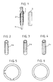
- the handle for a rotary dental instrument essentially consists of a hollow cylindrical sleeve (1) of metal, for example nickel silver, brass nickel plated or stainless steel and inside this sleeve is molded a plastic core (2).
- the tool rod (3) which will have been inserted prior to molding in the sleeve (1) so that its axis is substantially in the axis of the sleeve, is embedded in the plastic core (2) and therefore connected rigidly to him and to the sleeve.
- the notch (s) are executed inside the wall of the sleeve so as not to protrude from the ends of the sleeve (4a) constituting an anchor.
- FIG. 3 represents the notch (s) executed inside the wall of the sleeve so as to lead to one of the ends of the sleeve (4b).
- FIG. 4 represents the notches executed inside the wall of the sleeve so as to lead to the two ends of the sleeve (4c).
- the notch (s) may have a tail shape dovetail (see Figure 5) or a V shape (see Figure 6).
Landscapes
- Health & Medical Sciences (AREA)
- Engineering & Computer Science (AREA)
- Mechanical Engineering (AREA)
- Oral & Maxillofacial Surgery (AREA)
- Dentistry (AREA)
- Epidemiology (AREA)
- Life Sciences & Earth Sciences (AREA)
- Animal Behavior & Ethology (AREA)
- General Health & Medical Sciences (AREA)
- Public Health (AREA)
- Veterinary Medicine (AREA)
- Dental Tools And Instruments Or Auxiliary Dental Instruments (AREA)
Description
- la figure 1 est une vue en élévation et en coupe partielle du manche,
- les figures 2 à 4 sont des vues de profil des manchons correspondant à trois variantes d'exécution,
- la figure 5 représente une vue en coupe partielle du dessin du manche,
- la figure 6 représente une vue en coupe partielle d'une variante d'exécution illustrant un crantage en forme de V.
Claims (3)
- Manche pour instrument dentaire à canaux rotatifs constitué par un manchon (1) métallique cylindrique dans lequel est introduite l'extrémité non active de l'instrument, l'espace compris entre le manchon (1) et la tige (3) étant rempli par une matière plastique (2) qui constitue un noyau solidarisant le manchon et la tige et qui dépasse à l'extrémité du manchon pour former la tête d'instrument, au moins un ancrage étant prévu entre le manchon cylindrique et le noyau en matière plastique caractérisé en ce que l'ancrage est réalisé grâce à au moins un crantage longitudinal (4) réalisé sur la paroi interne du manchon cylindrique sur au moins une partie de sa longueur, crantage dans lequel se loge la matière plastique, ledit crantage ne s'étendant pas jusqu'aux extrémités du manchon.
- Manche pour instrument dentaire à canaux rotatifs selon la revendication 1, caractérisé en ce que le ou les crantages ont une forme en queue d'aronde.
- Manche pour instrument dentaire à canaux rotatifs selon la revendication 1, caractérisé en ce que le ou les crantages ont une forme en V.
Applications Claiming Priority (2)
| Application Number | Priority Date | Filing Date | Title |
|---|---|---|---|
| FR9604988 | 1996-04-17 | ||
| FR9604988A FR2747563B1 (fr) | 1996-04-17 | 1996-04-17 | Manche pour instrument dentaire rotatif |
Publications (2)
| Publication Number | Publication Date |
|---|---|
| EP0801929A1 EP0801929A1 (fr) | 1997-10-22 |
| EP0801929B1 true EP0801929B1 (fr) | 2002-07-10 |
Family
ID=9491416
Family Applications (1)
| Application Number | Title | Priority Date | Filing Date |
|---|---|---|---|
| EP97470003A Expired - Lifetime EP0801929B1 (fr) | 1996-04-17 | 1997-02-07 | Manche pour instrument dentaire rotatif |
Country Status (5)
| Country | Link |
|---|---|
| US (1) | US5897318A (fr) |
| EP (1) | EP0801929B1 (fr) |
| JP (1) | JPH1033560A (fr) |
| DE (1) | DE69713831T2 (fr) |
| FR (1) | FR2747563B1 (fr) |
Families Citing this family (10)
| Publication number | Priority date | Publication date | Assignee | Title |
|---|---|---|---|---|
| GB9930554D0 (en) * | 1999-12-23 | 2000-02-16 | Fiskars Uk Ltd | The manufacture of implements |
| FR2855962B1 (fr) * | 2003-06-12 | 2005-08-19 | Micro Mega Int Mfg Sa | Instrument dentaire mecanise. |
| EP1582171B1 (fr) * | 2004-03-29 | 2008-07-23 | Maillefer Instruments Holding S.A.R.L. | Instrument dentaire à usage unique |
| EP2135568B1 (fr) * | 2004-06-21 | 2011-12-07 | Straumann Holding AG | Procédé de fabrication d'outils de découpe rotatifs jetables et outil rotatif jetable pour applications dentaires ou médicales |
| US7682152B2 (en) | 2005-12-20 | 2010-03-23 | Ford Christopher W | Force distributing dental implant assembly |
| US20070141532A1 (en) * | 2005-12-20 | 2007-06-21 | Ford Christopher W | Force distributing dental implant assembly |
| US20070141533A1 (en) * | 2005-12-20 | 2007-06-21 | Ford Christopher W | Polymeric dental implant assembly |
| KR100959639B1 (ko) * | 2007-04-05 | 2010-05-26 | 이인환 | 근관치료기의 니들유닛 |
| US8011926B2 (en) | 2008-05-15 | 2011-09-06 | Ford Christopher W | Polymeric dental implant assembly |
| DE102010002557A1 (de) * | 2010-03-03 | 2011-09-08 | Sandvik Intellectual Property Ab | Zerspanungswerkzeug mit spielfreier Feinstverstellung |
Family Cites Families (8)
| Publication number | Priority date | Publication date | Assignee | Title |
|---|---|---|---|---|
| US628927A (en) * | 1898-08-20 | 1899-07-18 | Francis Ducharme | Tool-handle. |
| US2606366A (en) * | 1948-10-13 | 1952-08-12 | James B Stevens | Vibration dampening and insulating means for tools such as dental tools |
| US2871899A (en) * | 1958-04-16 | 1959-02-03 | Bridgeport Hardware Mfg Corp | Tool handles |
| DE1126560B (de) * | 1960-06-04 | 1962-03-29 | Finzler Schrock & Kimmel | Zahnaerztliches Instrument |
| US4321040A (en) * | 1980-12-09 | 1982-03-23 | Ipco Corporation | Endodontic instrument |
| EP0056198B1 (fr) * | 1981-01-06 | 1985-09-04 | Stuart Julian Filhol | Dispositif d'ancrage dentaire |
| FR2499446A1 (fr) * | 1981-02-12 | 1982-08-13 | Micro Mega Sa | Manche pour instrument dentaire a canaux, rotatif, et procede de fabrication d'un tel manche |
| CH669513A5 (fr) * | 1986-07-07 | 1989-03-31 | Maillefer Auguste Sa |
-
1996
- 1996-04-17 FR FR9604988A patent/FR2747563B1/fr not_active Expired - Fee Related
-
1997
- 1997-02-07 DE DE69713831T patent/DE69713831T2/de not_active Expired - Fee Related
- 1997-02-07 EP EP97470003A patent/EP0801929B1/fr not_active Expired - Lifetime
- 1997-04-16 US US08/840,742 patent/US5897318A/en not_active Expired - Fee Related
- 1997-04-17 JP JP9114220A patent/JPH1033560A/ja active Pending
Also Published As
| Publication number | Publication date |
|---|---|
| DE69713831D1 (de) | 2002-08-14 |
| EP0801929A1 (fr) | 1997-10-22 |
| DE69713831T2 (de) | 2003-03-27 |
| JPH1033560A (ja) | 1998-02-10 |
| US5897318A (en) | 1999-04-27 |
| FR2747563A1 (fr) | 1997-10-24 |
| FR2747563B1 (fr) | 1998-06-05 |
Similar Documents
| Publication | Publication Date | Title |
|---|---|---|
| EP2023840B1 (fr) | Outil dynamometrique a usage medical | |
| FR2680461A1 (fr) | Implant pour dispositif d'osteosynthese notamment du rachis et dispositif correspondant pour sa mise en place. | |
| FR2621465A1 (fr) | Brosse interdentaire | |
| CH644049A5 (fr) | Manche destine a etre utilise en liaison avec un outil en forme de ''l''. | |
| FR2516416A1 (fr) | Outil a moteur comportant un carter en matiere plastique | |
| EP0801929A1 (fr) | Manche pour instrument dentaire rotatif | |
| FR2681223A1 (fr) | Dispositif d'aide a la marche, de type bequille ou canne anglaise. | |
| FR2465469A1 (fr) | Instrument pour le traitement des canaux dentaires | |
| EP0909870A1 (fr) | Accouplement pour dispositif à transmission de forces | |
| EP0880943A1 (fr) | Outil de vissage d'une vis à deux parties filetées séparées par une partie intermédiaire de vissage | |
| CH646045A5 (fr) | Manche pour instrument dentaire a canaux, rotatif, et procede de fabrication d'un tel manche. | |
| FR2465468A1 (fr) | Outil dentaire et son porte-outil | |
| WO2014140448A1 (fr) | Instrument chirurgical rotatif et/ou vibrant adapté pour distribuer un fluide | |
| FR2681517A1 (fr) | Support de brosse a dents a fixation amovible. | |
| EP0283377B1 (fr) | Douille de raccordement d'un manche cylindrique ou ovale à l'oeil coniqe d'un outil | |
| FR2880534A1 (fr) | Jeu de butees positives et encliquetables pour contre-angle de dentisterie et son support de presentation | |
| CH628799A5 (fr) | Dispositif de fixation d'un instrument dentaire dans une piece a main. | |
| BE1014828A6 (fr) | Creuse pomme de terre. | |
| FR2834630A1 (fr) | Cupule pour implant cotyloidien | |
| FR2834526A1 (fr) | Amenagement de cordeliere pour la constitution de main courante ou de barriere de separation | |
| FR2662587A1 (fr) | Mecanisme pour boitier porte-rouge a levres. | |
| WO2008129217A2 (fr) | Manche d'instrument canalaire réalisé en deux parties coaxiales solidarisées en translation axiale et en rotation | |
| FR2828124A3 (fr) | Vis sans fin de reglage perfectionnee pour cle | |
| FR2530225A1 (fr) | Dispositif pour proteger le filetage realise aux extremites d'une piece tubulaire | |
| FR2671025A1 (fr) | Porte-ecrou autobloquant de presentation. |
Legal Events
| Date | Code | Title | Description |
|---|---|---|---|
| PUAI | Public reference made under article 153(3) epc to a published international application that has entered the european phase |
Free format text: ORIGINAL CODE: 0009012 |
|
| AK | Designated contracting states |
Kind code of ref document: A1 Designated state(s): CH DE ES GB IT LI SE |
|
| 17P | Request for examination filed |
Effective date: 19980310 |
|
| 17Q | First examination report despatched |
Effective date: 20000705 |
|
| GRAG | Despatch of communication of intention to grant |
Free format text: ORIGINAL CODE: EPIDOS AGRA |
|
| GRAG | Despatch of communication of intention to grant |
Free format text: ORIGINAL CODE: EPIDOS AGRA |
|
| GRAH | Despatch of communication of intention to grant a patent |
Free format text: ORIGINAL CODE: EPIDOS IGRA |
|
| GRAH | Despatch of communication of intention to grant a patent |
Free format text: ORIGINAL CODE: EPIDOS IGRA |
|
| GRAA | (expected) grant |
Free format text: ORIGINAL CODE: 0009210 |
|
| AK | Designated contracting states |
Kind code of ref document: B1 Designated state(s): CH DE ES GB IT LI SE |
|
| PG25 | Lapsed in a contracting state [announced via postgrant information from national office to epo] |
Ref country code: IT Free format text: LAPSE BECAUSE OF FAILURE TO SUBMIT A TRANSLATION OF THE DESCRIPTION OR TO PAY THE FEE WITHIN THE PRE;WARNING: LAPSES OF ITALIAN PATENTS WITH EFFECTIVE DATE BEFORE 2007 MAY HAVE OCCURRED AT ANY TIME BEFORE 2007. THE CORRECT EFFECTIVE DATE MAY BE DIFFERENT FROM THE ONE RECORDED.SCRIBED TIME-LIMIT Effective date: 20020710 Ref country code: GB Free format text: LAPSE BECAUSE OF FAILURE TO SUBMIT A TRANSLATION OF THE DESCRIPTION OR TO PAY THE FEE WITHIN THE PRESCRIBED TIME-LIMIT Effective date: 20020710 |
|
| REG | Reference to a national code |
Ref country code: GB Ref legal event code: FG4D Free format text: NOT ENGLISH |
|
| REG | Reference to a national code |
Ref country code: CH Ref legal event code: EP |
|
| REF | Corresponds to: |
Ref document number: 69713831 Country of ref document: DE Date of ref document: 20020814 |
|
| REG | Reference to a national code |
Ref country code: CH Ref legal event code: NV Representative=s name: SPIERENBURG HELMLE-KOLB & PARTNER AG PATENT- UND M |
|
| PG25 | Lapsed in a contracting state [announced via postgrant information from national office to epo] |
Ref country code: SE Free format text: LAPSE BECAUSE OF FAILURE TO SUBMIT A TRANSLATION OF THE DESCRIPTION OR TO PAY THE FEE WITHIN THE PRESCRIBED TIME-LIMIT Effective date: 20021010 |
|
| GBV | Gb: ep patent (uk) treated as always having been void in accordance with gb section 77(7)/1977 [no translation filed] |
Effective date: 20020710 |
|
| PG25 | Lapsed in a contracting state [announced via postgrant information from national office to epo] |
Ref country code: ES Free format text: LAPSE BECAUSE OF FAILURE TO SUBMIT A TRANSLATION OF THE DESCRIPTION OR TO PAY THE FEE WITHIN THE PRESCRIBED TIME-LIMIT Effective date: 20030130 |
|
| PG25 | Lapsed in a contracting state [announced via postgrant information from national office to epo] |
Ref country code: LI Free format text: LAPSE BECAUSE OF NON-PAYMENT OF DUE FEES Effective date: 20030228 Ref country code: CH Free format text: LAPSE BECAUSE OF NON-PAYMENT OF DUE FEES Effective date: 20030228 |
|
| PLBE | No opposition filed within time limit |
Free format text: ORIGINAL CODE: 0009261 |
|
| STAA | Information on the status of an ep patent application or granted ep patent |
Free format text: STATUS: NO OPPOSITION FILED WITHIN TIME LIMIT |
|
| 26N | No opposition filed |
Effective date: 20030411 |
|
| PG25 | Lapsed in a contracting state [announced via postgrant information from national office to epo] |
Ref country code: DE Free format text: LAPSE BECAUSE OF NON-PAYMENT OF DUE FEES Effective date: 20030902 |
|
| REG | Reference to a national code |
Ref country code: CH Ref legal event code: PL |