EP0801935A2 - Prothetische Gelenkpfanne - Google Patents
Prothetische Gelenkpfanne Download PDFInfo
- Publication number
- EP0801935A2 EP0801935A2 EP97105338A EP97105338A EP0801935A2 EP 0801935 A2 EP0801935 A2 EP 0801935A2 EP 97105338 A EP97105338 A EP 97105338A EP 97105338 A EP97105338 A EP 97105338A EP 0801935 A2 EP0801935 A2 EP 0801935A2
- Authority
- EP
- European Patent Office
- Prior art keywords
- shell body
- ball head
- socket
- locking ring
- ring
- Prior art date
- Legal status (The legal status is an assumption and is not a legal conclusion. Google has not performed a legal analysis and makes no representation as to the accuracy of the status listed.)
- Granted
Links
Images
Classifications
-
- A—HUMAN NECESSITIES
- A61—MEDICAL OR VETERINARY SCIENCE; HYGIENE
- A61F—FILTERS IMPLANTABLE INTO BLOOD VESSELS; PROSTHESES; DEVICES PROVIDING PATENCY TO, OR PREVENTING COLLAPSING OF, TUBULAR STRUCTURES OF THE BODY, e.g. STENTS; ORTHOPAEDIC, NURSING OR CONTRACEPTIVE DEVICES; FOMENTATION; TREATMENT OR PROTECTION OF EYES OR EARS; BANDAGES, DRESSINGS OR ABSORBENT PADS; FIRST-AID KITS
- A61F2/00—Filters implantable into blood vessels; Prostheses, i.e. artificial substitutes or replacements for parts of the body; Appliances for connecting them with the body; Devices providing patency to, or preventing collapsing of, tubular structures of the body, e.g. stents
- A61F2/02—Prostheses implantable into the body
- A61F2/30—Joints
- A61F2/32—Joints for the hip
- A61F2/36—Femoral heads ; Femoral endoprostheses
- A61F2/3609—Femoral heads or necks; Connections of endoprosthetic heads or necks to endoprosthetic femoral shafts
-
- A—HUMAN NECESSITIES
- A61—MEDICAL OR VETERINARY SCIENCE; HYGIENE
- A61F—FILTERS IMPLANTABLE INTO BLOOD VESSELS; PROSTHESES; DEVICES PROVIDING PATENCY TO, OR PREVENTING COLLAPSING OF, TUBULAR STRUCTURES OF THE BODY, e.g. STENTS; ORTHOPAEDIC, NURSING OR CONTRACEPTIVE DEVICES; FOMENTATION; TREATMENT OR PROTECTION OF EYES OR EARS; BANDAGES, DRESSINGS OR ABSORBENT PADS; FIRST-AID KITS
- A61F2/00—Filters implantable into blood vessels; Prostheses, i.e. artificial substitutes or replacements for parts of the body; Appliances for connecting them with the body; Devices providing patency to, or preventing collapsing of, tubular structures of the body, e.g. stents
- A61F2/02—Prostheses implantable into the body
- A61F2/30—Joints
- A61F2002/30001—Additional features of subject-matter classified in A61F2/28, A61F2/30 and subgroups thereof
- A61F2002/30316—The prosthesis having different structural features at different locations within the same prosthesis; Connections between prosthetic parts; Special structural features of bone or joint prostheses not otherwise provided for
- A61F2002/30329—Connections or couplings between prosthetic parts, e.g. between modular parts; Connecting elements
- A61F2002/30331—Connections or couplings between prosthetic parts, e.g. between modular parts; Connecting elements made by longitudinally pushing a protrusion into a complementarily-shaped recess, e.g. held by friction fit
- A61F2002/30332—Conically- or frustoconically-shaped protrusion and recess
-
- A—HUMAN NECESSITIES
- A61—MEDICAL OR VETERINARY SCIENCE; HYGIENE
- A61F—FILTERS IMPLANTABLE INTO BLOOD VESSELS; PROSTHESES; DEVICES PROVIDING PATENCY TO, OR PREVENTING COLLAPSING OF, TUBULAR STRUCTURES OF THE BODY, e.g. STENTS; ORTHOPAEDIC, NURSING OR CONTRACEPTIVE DEVICES; FOMENTATION; TREATMENT OR PROTECTION OF EYES OR EARS; BANDAGES, DRESSINGS OR ABSORBENT PADS; FIRST-AID KITS
- A61F2/00—Filters implantable into blood vessels; Prostheses, i.e. artificial substitutes or replacements for parts of the body; Appliances for connecting them with the body; Devices providing patency to, or preventing collapsing of, tubular structures of the body, e.g. stents
- A61F2/02—Prostheses implantable into the body
- A61F2/30—Joints
- A61F2002/30001—Additional features of subject-matter classified in A61F2/28, A61F2/30 and subgroups thereof
- A61F2002/30316—The prosthesis having different structural features at different locations within the same prosthesis; Connections between prosthetic parts; Special structural features of bone or joint prostheses not otherwise provided for
- A61F2002/30329—Connections or couplings between prosthetic parts, e.g. between modular parts; Connecting elements
- A61F2002/30476—Connections or couplings between prosthetic parts, e.g. between modular parts; Connecting elements locked by an additional locking mechanism
- A61F2002/30487—Circumferential cooperating grooves and beads on cooperating lateral surfaces of a mainly longitudinal connection
-
- A—HUMAN NECESSITIES
- A61—MEDICAL OR VETERINARY SCIENCE; HYGIENE
- A61F—FILTERS IMPLANTABLE INTO BLOOD VESSELS; PROSTHESES; DEVICES PROVIDING PATENCY TO, OR PREVENTING COLLAPSING OF, TUBULAR STRUCTURES OF THE BODY, e.g. STENTS; ORTHOPAEDIC, NURSING OR CONTRACEPTIVE DEVICES; FOMENTATION; TREATMENT OR PROTECTION OF EYES OR EARS; BANDAGES, DRESSINGS OR ABSORBENT PADS; FIRST-AID KITS
- A61F2/00—Filters implantable into blood vessels; Prostheses, i.e. artificial substitutes or replacements for parts of the body; Appliances for connecting them with the body; Devices providing patency to, or preventing collapsing of, tubular structures of the body, e.g. stents
- A61F2/02—Prostheses implantable into the body
- A61F2/30—Joints
- A61F2002/30001—Additional features of subject-matter classified in A61F2/28, A61F2/30 and subgroups thereof
- A61F2002/30316—The prosthesis having different structural features at different locations within the same prosthesis; Connections between prosthetic parts; Special structural features of bone or joint prostheses not otherwise provided for
- A61F2002/30329—Connections or couplings between prosthetic parts, e.g. between modular parts; Connecting elements
- A61F2002/30476—Connections or couplings between prosthetic parts, e.g. between modular parts; Connecting elements locked by an additional locking mechanism
- A61F2002/305—Snap connection
-
- A—HUMAN NECESSITIES
- A61—MEDICAL OR VETERINARY SCIENCE; HYGIENE
- A61F—FILTERS IMPLANTABLE INTO BLOOD VESSELS; PROSTHESES; DEVICES PROVIDING PATENCY TO, OR PREVENTING COLLAPSING OF, TUBULAR STRUCTURES OF THE BODY, e.g. STENTS; ORTHOPAEDIC, NURSING OR CONTRACEPTIVE DEVICES; FOMENTATION; TREATMENT OR PROTECTION OF EYES OR EARS; BANDAGES, DRESSINGS OR ABSORBENT PADS; FIRST-AID KITS
- A61F2/00—Filters implantable into blood vessels; Prostheses, i.e. artificial substitutes or replacements for parts of the body; Appliances for connecting them with the body; Devices providing patency to, or preventing collapsing of, tubular structures of the body, e.g. stents
- A61F2/02—Prostheses implantable into the body
- A61F2/30—Joints
- A61F2/30767—Special external or bone-contacting surface, e.g. coating for improving bone ingrowth
- A61F2/30771—Special external or bone-contacting surface, e.g. coating for improving bone ingrowth applied in original prostheses, e.g. holes or grooves
- A61F2002/3082—Grooves
-
- A—HUMAN NECESSITIES
- A61—MEDICAL OR VETERINARY SCIENCE; HYGIENE
- A61F—FILTERS IMPLANTABLE INTO BLOOD VESSELS; PROSTHESES; DEVICES PROVIDING PATENCY TO, OR PREVENTING COLLAPSING OF, TUBULAR STRUCTURES OF THE BODY, e.g. STENTS; ORTHOPAEDIC, NURSING OR CONTRACEPTIVE DEVICES; FOMENTATION; TREATMENT OR PROTECTION OF EYES OR EARS; BANDAGES, DRESSINGS OR ABSORBENT PADS; FIRST-AID KITS
- A61F2/00—Filters implantable into blood vessels; Prostheses, i.e. artificial substitutes or replacements for parts of the body; Appliances for connecting them with the body; Devices providing patency to, or preventing collapsing of, tubular structures of the body, e.g. stents
- A61F2/02—Prostheses implantable into the body
- A61F2/30—Joints
- A61F2/32—Joints for the hip
- A61F2002/3233—Joints for the hip having anti-luxation means for preventing complete dislocation of the femoral head from the acetabular cup
-
- A—HUMAN NECESSITIES
- A61—MEDICAL OR VETERINARY SCIENCE; HYGIENE
- A61F—FILTERS IMPLANTABLE INTO BLOOD VESSELS; PROSTHESES; DEVICES PROVIDING PATENCY TO, OR PREVENTING COLLAPSING OF, TUBULAR STRUCTURES OF THE BODY, e.g. STENTS; ORTHOPAEDIC, NURSING OR CONTRACEPTIVE DEVICES; FOMENTATION; TREATMENT OR PROTECTION OF EYES OR EARS; BANDAGES, DRESSINGS OR ABSORBENT PADS; FIRST-AID KITS
- A61F2/00—Filters implantable into blood vessels; Prostheses, i.e. artificial substitutes or replacements for parts of the body; Appliances for connecting them with the body; Devices providing patency to, or preventing collapsing of, tubular structures of the body, e.g. stents
- A61F2/02—Prostheses implantable into the body
- A61F2/30—Joints
- A61F2/32—Joints for the hip
- A61F2002/3241—Joints for the hip having a ring, e.g. for locking the femoral head into the acetabular cup
-
- A—HUMAN NECESSITIES
- A61—MEDICAL OR VETERINARY SCIENCE; HYGIENE
- A61F—FILTERS IMPLANTABLE INTO BLOOD VESSELS; PROSTHESES; DEVICES PROVIDING PATENCY TO, OR PREVENTING COLLAPSING OF, TUBULAR STRUCTURES OF THE BODY, e.g. STENTS; ORTHOPAEDIC, NURSING OR CONTRACEPTIVE DEVICES; FOMENTATION; TREATMENT OR PROTECTION OF EYES OR EARS; BANDAGES, DRESSINGS OR ABSORBENT PADS; FIRST-AID KITS
- A61F2/00—Filters implantable into blood vessels; Prostheses, i.e. artificial substitutes or replacements for parts of the body; Appliances for connecting them with the body; Devices providing patency to, or preventing collapsing of, tubular structures of the body, e.g. stents
- A61F2/02—Prostheses implantable into the body
- A61F2/30—Joints
- A61F2/32—Joints for the hip
- A61F2/34—Acetabular cups
- A61F2002/348—Additional features
- A61F2002/3493—Spherical shell significantly greater than a hemisphere, e.g. extending over more than 200 degrees
-
- A—HUMAN NECESSITIES
- A61—MEDICAL OR VETERINARY SCIENCE; HYGIENE
- A61F—FILTERS IMPLANTABLE INTO BLOOD VESSELS; PROSTHESES; DEVICES PROVIDING PATENCY TO, OR PREVENTING COLLAPSING OF, TUBULAR STRUCTURES OF THE BODY, e.g. STENTS; ORTHOPAEDIC, NURSING OR CONTRACEPTIVE DEVICES; FOMENTATION; TREATMENT OR PROTECTION OF EYES OR EARS; BANDAGES, DRESSINGS OR ABSORBENT PADS; FIRST-AID KITS
- A61F2/00—Filters implantable into blood vessels; Prostheses, i.e. artificial substitutes or replacements for parts of the body; Appliances for connecting them with the body; Devices providing patency to, or preventing collapsing of, tubular structures of the body, e.g. stents
- A61F2/02—Prostheses implantable into the body
- A61F2/30—Joints
- A61F2/32—Joints for the hip
- A61F2/36—Femoral heads ; Femoral endoprostheses
- A61F2/3609—Femoral heads or necks; Connections of endoprosthetic heads or necks to endoprosthetic femoral shafts
- A61F2002/3611—Heads or epiphyseal parts of femur
-
- A—HUMAN NECESSITIES
- A61—MEDICAL OR VETERINARY SCIENCE; HYGIENE
- A61F—FILTERS IMPLANTABLE INTO BLOOD VESSELS; PROSTHESES; DEVICES PROVIDING PATENCY TO, OR PREVENTING COLLAPSING OF, TUBULAR STRUCTURES OF THE BODY, e.g. STENTS; ORTHOPAEDIC, NURSING OR CONTRACEPTIVE DEVICES; FOMENTATION; TREATMENT OR PROTECTION OF EYES OR EARS; BANDAGES, DRESSINGS OR ABSORBENT PADS; FIRST-AID KITS
- A61F2/00—Filters implantable into blood vessels; Prostheses, i.e. artificial substitutes or replacements for parts of the body; Appliances for connecting them with the body; Devices providing patency to, or preventing collapsing of, tubular structures of the body, e.g. stents
- A61F2/02—Prostheses implantable into the body
- A61F2/30—Joints
- A61F2/32—Joints for the hip
- A61F2/36—Femoral heads ; Femoral endoprostheses
- A61F2/3609—Femoral heads or necks; Connections of endoprosthetic heads or necks to endoprosthetic femoral shafts
- A61F2002/365—Connections of heads to necks
-
- A—HUMAN NECESSITIES
- A61—MEDICAL OR VETERINARY SCIENCE; HYGIENE
- A61F—FILTERS IMPLANTABLE INTO BLOOD VESSELS; PROSTHESES; DEVICES PROVIDING PATENCY TO, OR PREVENTING COLLAPSING OF, TUBULAR STRUCTURES OF THE BODY, e.g. STENTS; ORTHOPAEDIC, NURSING OR CONTRACEPTIVE DEVICES; FOMENTATION; TREATMENT OR PROTECTION OF EYES OR EARS; BANDAGES, DRESSINGS OR ABSORBENT PADS; FIRST-AID KITS
- A61F2/00—Filters implantable into blood vessels; Prostheses, i.e. artificial substitutes or replacements for parts of the body; Appliances for connecting them with the body; Devices providing patency to, or preventing collapsing of, tubular structures of the body, e.g. stents
- A61F2/02—Prostheses implantable into the body
- A61F2/30—Joints
- A61F2/32—Joints for the hip
- A61F2/36—Femoral heads ; Femoral endoprostheses
- A61F2/3609—Femoral heads or necks; Connections of endoprosthetic heads or necks to endoprosthetic femoral shafts
- A61F2002/3654—Connections of heads directly to shafts
-
- A—HUMAN NECESSITIES
- A61—MEDICAL OR VETERINARY SCIENCE; HYGIENE
- A61F—FILTERS IMPLANTABLE INTO BLOOD VESSELS; PROSTHESES; DEVICES PROVIDING PATENCY TO, OR PREVENTING COLLAPSING OF, TUBULAR STRUCTURES OF THE BODY, e.g. STENTS; ORTHOPAEDIC, NURSING OR CONTRACEPTIVE DEVICES; FOMENTATION; TREATMENT OR PROTECTION OF EYES OR EARS; BANDAGES, DRESSINGS OR ABSORBENT PADS; FIRST-AID KITS
- A61F2220/00—Fixations or connections for prostheses classified in groups A61F2/00 - A61F2/26 or A61F2/82 or A61F9/00 or A61F11/00 or subgroups thereof
- A61F2220/0025—Connections or couplings between prosthetic parts, e.g. between modular parts; Connecting elements
- A61F2220/0033—Connections or couplings between prosthetic parts, e.g. between modular parts; Connecting elements made by longitudinally pushing a protrusion into a complementary-shaped recess, e.g. held by friction fit
-
- A—HUMAN NECESSITIES
- A61—MEDICAL OR VETERINARY SCIENCE; HYGIENE
- A61F—FILTERS IMPLANTABLE INTO BLOOD VESSELS; PROSTHESES; DEVICES PROVIDING PATENCY TO, OR PREVENTING COLLAPSING OF, TUBULAR STRUCTURES OF THE BODY, e.g. STENTS; ORTHOPAEDIC, NURSING OR CONTRACEPTIVE DEVICES; FOMENTATION; TREATMENT OR PROTECTION OF EYES OR EARS; BANDAGES, DRESSINGS OR ABSORBENT PADS; FIRST-AID KITS
- A61F2310/00—Prostheses classified in A61F2/28 or A61F2/30 - A61F2/44 being constructed from or coated with a particular material
- A61F2310/00005—The prosthesis being constructed from a particular material
- A61F2310/00179—Ceramics or ceramic-like structures
Definitions
- the invention relates to a prosthetic socket for receiving a spherical head.
- implantable socket members are used to hold a ball head.
- the joint socket essentially consists of an outer shell and an inner shell inserted therein.
- a joint socket is known from EP-A-0 234 811, the outer shell of which is made of metal and the inner shell of which is made of plastic.
- the ball head used can plastically deform the plastic inner shell at high pressures, which changes the joint geometry.
- a joint socket is known from EP-A-0 315 795, the outer shell of which is made of plastic and the inner shell of which is made of metal. Because of the low strength of the plastic, there may also be loosening of the socket in the bone. The friction of the joint ball in the metal inner shell releases metal particles that can penetrate into the surrounding tissue.
- the object of the invention is to provide an improved prosthetic socket.
- the joint socket is formed by a single, one-piece shell body.
- the inside of the shell body serves to hold the ball head, while the outside is implanted in the bone.
- the construction and manufacture of this joint socket include greatly simplified by the omission of connecting elements.
- the shell body is made of ceramic, which means that when using a ceramic ball head, a very exact gap and play-free mounting of the Ball head is made possible. This does not change because of the same expansion coefficients of the ceramic ball head and the ceramic shell body, even when the temperature changes.
- the ceramic is very hard to wear due to its hardness, so that there is no significant abrasion that could penetrate into neighboring tissue. Furthermore, the ceramic is very wear-resistant, which, when using a ceramic ball head, can have the effect that even with heavily stressed joint prostheses, for example hip prostheses, the joint socket has a very long service life and replacement of the joint socket is avoided.
- a removable locking ring for securing the inserted ball head is preferably provided in a circumferential recess on the opening edge of the shell body.
- the inner diameter of the locking ring is smaller than the diameter of the ball head.
- the locking ring holds the ball head in the shell body. This prevents the ball head from being briefly pulled out of the socket or from escaping completely. By avoiding even smaller exits of the ball head from the shell body, damage and wear are avoided which can occur when the ball head snaps back into the socket.
- the locking ring increases the lifespan of the socket.
- the securing ring can have a circumferential web on its outside, which engages with a circumferential groove on the inside of the shell body.
- the locking ring is engaged by snapping the web into the groove attached to the shell body with simple means.
- the retaining ring preferably has a lower hardness than the ball head material and is preferably made of polyethylene.
- the disengaging movements of the ball head in the area of the circlip can cause large disengagement forces which have to be absorbed by the circlip.
- the ball head is elastically braked in its disengaging movement and scratches and damage to the ball head are avoided by the locking ring.
- the retaining ring can also have a circumferential groove on its outside, which increases the axial deformability of the retaining ring and thereby also ensures that the emerging ball head is braked more elastically.
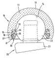
- the figure shows a longitudinal section of a one-piece shell body with an inserted circlip.
- a prosthetic socket 10 is formed by a one-piece shell body 11 made of ceramic and a locking ring 30.
- the outer side wall 13 and the inner side wall 14 of the shell body 11 are each spherical.
- a spherical head prosthesis 20 is inserted into the socket 10, which consists of a spherical ball head 22 and the prosthesis shaft 21.
- the outer diameter of the spherical head 22 is approximately equal to the inner diameter of the spherical inner side wall 14 of the socket 10, so that the spherical head 22 is mounted in the shell body 11 without any gaps or play. This ensures a large-area transmission of compressive forces between the socket 10 and the ball head prosthesis 20.
- the locking ring 30 is used, which is formed by a ring-shaped profiled ring body 31 made of polyethylene.
- the ring body 31 is inserted into a circumferential recess 35 at the opening edge of the shell body 11, so that the ring body 21 does not protrude into the spherical recess of the shell body 11.
- the inner circumferential side 34 of the ring body 31 facing the interior of the shell body is concavely curved in cross section and continues the hemispherical inner side wall 14 of the shell body 11 toward the opening side.
- the inner circumference or diameter is smaller than the outer circumference or the diameter of the spherical head 22.
- the shell body 11 has a radial circumferential groove 37 in the recess 35, into which a radial circumferential web 38 of the ring body 31 engages.
- the ring body 31 is secured to the shell body against the disengagement forces of the ball head 22.
- the locking ring 30 can possibly with simple means are removed to separate the ball head prosthesis 20 from the socket 10.
- a radial circumferential groove 41 is embedded on the outside of the ring body 31. It brings about better deformation properties of the ring body 31 in the axial direction, as a result of which the spring action of the locking ring 30 is improved. When the ball head 22 exits, the ring body 31 yields resiliently, as a result of which the outward movement of the ball head 22 is braked gently.
- the retaining ring can also be made of other materials, which, however, should be softer than the shell body ceramic and as elastic as possible.
- the one-piece ceramic shell body creates a joint socket that offers high joint precision and a long service life.
Landscapes
- Health & Medical Sciences (AREA)
- Orthopedic Medicine & Surgery (AREA)
- Cardiology (AREA)
- Oral & Maxillofacial Surgery (AREA)
- Transplantation (AREA)
- Engineering & Computer Science (AREA)
- Biomedical Technology (AREA)
- Heart & Thoracic Surgery (AREA)
- Vascular Medicine (AREA)
- Life Sciences & Earth Sciences (AREA)
- Animal Behavior & Ethology (AREA)
- General Health & Medical Sciences (AREA)
- Public Health (AREA)
- Veterinary Medicine (AREA)
- Prostheses (AREA)
Abstract
Description
- Die Erfindung bezieht sich auf eine prothetische Gelenkpfanne zur Aufnahme eines Kugelkopfes.
- Bei einem prothetischen Gelenk werden zur Aufnahme eines Kugelkopfes implatierbare Gelenkpfannen verwendet. Die Gelenkpfanne besteht im wesentlichen aus einer Außenschale und aus einer darin eingesetzten Innenschale.
- Aus EP-A-0 234 811 ist eine Gelenkpfanne bekannt, deren Außenschale aus Metall und deren Innenschale aus Kunststoff besteht. Bei großen Belastungen kann der eingesetzte Kugelkopf mit hohen Drücken die Kunststoffinnenschale plastisch verformen, wodurch die Gelenkgeometrie verändert wird. Ferner entsteht Abrieb der Kunststoffinnenschale, der in das angrenzende Gewebe gelangen kann.
- Aus EP-A-0 315 795 ist eine Gelenkpfanne bekannt, deren Außenschale aus Kunststoff und deren Innenschale aus Metall besteht. Wegen der geringen Festigkeit des Kunststoffs kann es auch hier zu Lockerungen des Gelenkpfannensitzes im Knochen kommen. Durch die Reibung der Gelenkkugel in der Metallinnenschale werden Metallpartikel freigesetzt, die in das umliegende Gewebe eindringen können.
- Die Befestigung der Innenschale in der Außenschale erfordert besondere konstruktive Maßnahmen, wie die Verwendung von Sicherungsringen, Verklebung oder Verklemmung. Bei starker mechanischer Beanspruchung wird die Substanz der Innenschalen reduziert, weshalb eine regelmäßige Kontrolle und ggf. ein Austausch der Innenschale erforderlich ist.
- Aufgabe der Erfindung ist es, eine verbesserte prothetische Gelenkpfanne zu schaffen.
- Die Aufgabe wird erfindungsgemäß durch die Merkmale des Anspruchs 1 gelöst.
- Die Gelenkpfanne wird von einem einzigen einstückigen Schalenkörper gebildet. Der Schalenkörper dient an seiner Innenseite der Aufnahme des Kugelkopfes, während seine Außenseite in den Knochen implantiert wird. Die Konstruktion und Herstellung dieser Gelenkpfanne ist u.a. durch den Wegfall von Verbindungselementen stark vereinfacht.
- Der Schalenkörper besteht aus Keramik, wodurch insbesondere bei Verwendung eines keramischen Kugelkopfes eine sehr exakte spalt- und spielfreie Lagerung des Kugelkopfes ermöglicht wird. Dies ändert sich wegen der gleichen Ausdehnungskoeffizienten des keramischem Kugelkopfes und des keramischen Schalenkörpers auch nicht bei Temperaturänderungen.
- Die Keramik ist aufgrund ihrer Härte sehr verschleißarm, so daß kein nennenswerter Abrieb auftritt, der in benachbartes Gewebe eindringen könnte. Ferner ist die Keramik sehr verschleißfest, was bei Verwendung eines Keramikkugelkopfes bewirken kann, daß auch bei stark beanspruchten Gelenkprothesen, beispielsweise Hüftprothesen, eine sehr lange Lebensdauer der Gelenkpfanne erreicht und ein Auswechseln der Gelenkpfanne vermieden wird.
- Vorzugsweise ist am Öffnungsrand des Schalenkörpers in einer umlaufenden Ausnehmung ein entfernbarer Sicherungsring zum Sichern des eingesteckten Kugelkopfes vorgesehen. Der Innendurchmesser des Sicherungsrings ist kleiner als der Durchmesser des Kugelkopfes. Der Sicherungsring hält den Kugelkopf in dem Schalenkörper fest. Dadurch wird verhindert, daß der Kugelkopf kurzzeitig aus der Gelenkpfanne gezogen wird, bzw. vollständig austritt. Durch Vermeidung auch kleinerer Austritte des Kugelkopfes aus dem Schalenkörper werden Beschädigungen und Verschleiß vermieden, die beim Zurückschnellen des Kugelkopfes in die Gelenkpfanne auftreten können. Der Sicherungsring erhöht dadurch die Lebensdauer der Gelenkpfanne.
- Der Sicherungsring kann an seiner Außenseite einen umlaufenden Steg aufweisen, der mit einer umlaufenden Nut an der Innenseite des Schalenkörpers zusammengreift. Durch Einrasten des Steges in die Nut wird der Sicherungsring an dem Schalenkörper mit einfachen Mitteln befestigt.
- Der Sicherungsring weist vorzugsweise eine geringere Härte auf, als das Kugelkopfmaterial und besteht vorzugsweise aus Polyethylen. Bei Zugbelastungen des Gelenks können die Ausrückbewegungen des Kugelkopfes im Bereich des Sicherungsringes große Ausrückkräfte bewirken, die von dem Sicherungsring aufgefangen werden müssen. Durch Wahl eines elastischen und weichen Sicherungsring-Materials wird der Kugelkopf in seiner Ausrückbewegung elastisch abgebremst und werden Kratzer und Beschädigungen des Kugelkopfes durch den Sicherungsring vermieden.
- Der Sicherungsring kann an seiner Außenseite auch eine umlaufende Nut aufweisen, die die axiale Verformbarkeit des Sicherungsringes erhöht und dadurch ebenfalls dafür sorgt, daß der austretende Kugelkopf elastischer abgebremst wird.
- Im folgenden wird unter Bezugnahme auf die Zeichnung ein Ausführungsbeispiel der Erfindung näher erläutert.
- Die Figur zeigt einen Längsschnitt eines einstückigen Schalenkörpers mit eingesetztem Sicherungsring.
- Eine prothetische Gelenkpfanne 10 wird von einem einstückigen Schalenkörper 11 aus Keramik und einem Sicherungsring 30 gebildet. Die Außenseitenwand 13 und die Innenseitenwand 14 des Schalenkörpers 11 sind jeweils kugelförmig ausgebildet.
- In die Gelenkpfanne 10 ist eine Kugelkopfprothese 20 eingesteckt, die aus einem kugelförmigen Kugelkopf 22 und dem Prothesenschaft 21 besteht. Der Außendurchmesser des Kugelkopfes 22 ist annähernd gleich dem Innendurchmesser der kugelförmigen Innenseitenwand 14 der Gelenkpfanne 10, so daß der Kugelkopf 22 in dem Schalenkörper 11 spalt- und spielfrei gelagert ist. Dadurch wird eine großflächige Übertragung von Druckkräften zwischen der Gelenkpfanne 10 und der Kugelkopfprothese 20 gewährleistet.
- Im Bereich des Öffnungsrandes des Schalenkörpers 11 ist der Sicherungsring 30 eingesetzt, der von einem ringartigen profilierten Ringkörper 31 aus Polyethylen gebildet wird. Der Ringkörper 31 ist in eine umlaufende Ausnehmung 35 am Öffnungsrand des Schalenkörpers 11 eingesetzt, so daß der Ringkörper 21 nicht in die kugelförmige Ausnehmung des Schalenkörpers 11 hineinragt. Die dem Schalenkörperinnenraum zugewandte Innenumfangsseite 34 des Ringkörpers 31 ist im Querschnitt konkav gewölbt und setzt die halbkugelförmige Innenseitenwand 14 des Schalenkörpers 11 zur Öffnungsseite hin fort. An der öffnungsseitigen Kante 36 der Innenumfangsseite 34 ist der Innenumfang bzw. Durchmesser kleiner als der Außenumfang bzw. der Durchmesser des Kugelkopfes 22. Bei eingesetztem Sicherungsring 20 kann der Kugelkopf 22 daher nicht aus dem Schalenkörper 11 heraustreten.
- Der Schalenkörper 11 weist in der Ausnehmung 35 eine radiale umlaufende Nut 37 auf, in die ein radialer umlaufender Steg 38 des Ringkörpers 31 eingreift. Dadurch wird der Ringkörper 31 an dem Schalenkörper gegen die Ausrückkräfte des Kugelkopfes 22 gesichert. Dennoch kann der Sicherungsring 30 ggf. mit einfachen Mitteln entfernt werden, um die Kugelkopfprothese 20 von der Gelenkpfanne 10 zu trennen.
- An der Außenseite des Ringkörpers 31 ist eine radiale umlaufende Nut 41 eingelassen. Sie bewirkt bessere Verformungseigenschaften des Ringkörpers 31 in axialer Richtung, wodurch die Federwirkung des Sicherungsrings 30 verbessert wird. Bei einer Austrittsbewegung des Kugelkopfes 22 gibt der Ringkörper 31 federnd nach, wodurch die Auswärtsbewegung des Kugelkopfes 22 sanft abgebremst wird.
- Der Sicherungsring kann auch aus anderen Materialien bestehen, die jedoch weicher als die Schalenkörperkeramik und möglichst elastisch sein sollten.
- Mit dem einstückigen Schalenkörper aus Keramik ist eine Gelenkpfanne geschaffen, die eine hohe Gelenkpräzision und lange Lebensdauer bietet.
Claims (5)
- Prothetische Gelenkpfanne zur Aufnahme eines Kugelkopfes (20), wobeidie Gelenkpfanne von einem einzigen einstückigen Schalenkörper (11) gebildet wird, undder Schalenkörper (11) aus Keramik besteht.
- Prothetische Gelenkpfanne nach Anspruch 1, dadurch gekennzeichnet, daß am Öffnungsrand des Schalenkörpers (11) in einer umlaufenden Ausnehmung (35) ein entfernbarer Sicherungsring (30) zum Sichern des eingesteckten Kugelkopfes (20) vorgesehen ist, wobei der Innendurchmesser des Sicherungsrings (30) kleiner ist als der Durchmesser des Kugelkopfes (20).
- Prothetische Gelenkpfanne nach Anspruch 1 oder 2, dadurch gekennzeichnet, daß der Sicherungsring (30) an seiner Außenseite einen umlaufenden Steg (38) aufweist, der mit einer umlaufenden Nut (37) an der Innenseite des Schalenkörpers (11) zusammengreift.
- Prothetische Gelenkpfanne nach Anspruch 2 oder 3, dadurch gekennzeichnet, daß der Sicherungsring (30) aus einem Material besteht, das eine geringere Härte als das Kugelkopfmaterial aufweist, und vorzugsweise aus Polyethylen besteht.
- Prothetische Gelenkpfanne nach einem der Ansprüche 2 bis 4, dadurch gekennzeichnet, daß der Sicherungsring (30) an seiner Außenseite eine umlaufende Nut (41) aufweist.
Applications Claiming Priority (2)
| Application Number | Priority Date | Filing Date | Title |
|---|---|---|---|
| DE19615786 | 1996-04-20 | ||
| DE19615786A DE19615786A1 (de) | 1996-04-20 | 1996-04-20 | Prothetische Gelenkpfanne |
Publications (3)
| Publication Number | Publication Date |
|---|---|
| EP0801935A2 true EP0801935A2 (de) | 1997-10-22 |
| EP0801935A3 EP0801935A3 (de) | 1998-01-07 |
| EP0801935B1 EP0801935B1 (de) | 2002-07-03 |
Family
ID=7791941
Family Applications (1)
| Application Number | Title | Priority Date | Filing Date |
|---|---|---|---|
| EP97105338A Expired - Lifetime EP0801935B1 (de) | 1996-04-20 | 1997-03-29 | Prothetische Gelenkpfanne |
Country Status (3)
| Country | Link |
|---|---|
| EP (1) | EP0801935B1 (de) |
| AT (1) | ATE219911T1 (de) |
| DE (1) | DE19615786A1 (de) |
Cited By (1)
| Publication number | Priority date | Publication date | Assignee | Title |
|---|---|---|---|---|
| EP2561832A1 (de) | 2008-10-07 | 2013-02-27 | Finsbury (Development) Limited | Prothese |
Family Cites Families (8)
| Publication number | Priority date | Publication date | Assignee | Title |
|---|---|---|---|---|
| US4159544A (en) * | 1977-11-28 | 1979-07-03 | Zafmedico Corporation | Hip joint prosthesis |
| DD251074A1 (de) * | 1986-07-21 | 1987-11-04 | Karl Marx Stadt Tech Hochschul | Verschleissfeste hueftgelenkpfanne |
| DE3824243C1 (de) * | 1988-07-16 | 1990-04-12 | Friedrichsfeld Gmbh Keramik- Und Kunststoffwerke, 6800 Mannheim, De | |
| US4936855A (en) * | 1989-04-24 | 1990-06-26 | Intermedics, Orthopedics, Inc. | Stepped-lock ring system for implantable joint prostheses |
| US5314491A (en) * | 1990-02-02 | 1994-05-24 | Zimmer, Inc. | Prosthetic socket implant |
| DE9215863U1 (de) * | 1992-11-21 | 1993-05-27 | Bernhardt, Frank, 4000 Düsseldorf | Hüftgelenkendoprothese |
| DE4337936A1 (de) * | 1993-11-06 | 1995-05-11 | Cerasiv Gmbh | Sphärische Hüftgelenkpfanne |
| DE4402675A1 (de) * | 1993-11-26 | 1995-06-01 | Cerasiv Gmbh | Konische Hüftgelenkpfanne ohne Selbsthemmung |
-
1996
- 1996-04-20 DE DE19615786A patent/DE19615786A1/de not_active Withdrawn
-
1997
- 1997-03-29 EP EP97105338A patent/EP0801935B1/de not_active Expired - Lifetime
- 1997-03-29 AT AT97105338T patent/ATE219911T1/de not_active IP Right Cessation
Cited By (1)
| Publication number | Priority date | Publication date | Assignee | Title |
|---|---|---|---|---|
| EP2561832A1 (de) | 2008-10-07 | 2013-02-27 | Finsbury (Development) Limited | Prothese |
Also Published As
| Publication number | Publication date |
|---|---|
| EP0801935A3 (de) | 1998-01-07 |
| DE19615786A1 (de) | 1997-10-23 |
| EP0801935B1 (de) | 2002-07-03 |
| ATE219911T1 (de) | 2002-07-15 |
Similar Documents
| Publication | Publication Date | Title |
|---|---|---|
| DE69407667T2 (de) | Gelenkpfannenprothese, insbesondere für Hüft-Oberschenkelgelenk | |
| EP0445068B1 (de) | Künstliche Hüftgelenkspfanne | |
| EP0863731B1 (de) | Modulare endoprothese | |
| EP0668063B1 (de) | Schale für eine Gelenkprothese, insbesondere Hüftgelenkprothese und Einsatz zur Verwendung mit der Schale | |
| EP0098466B1 (de) | Implantierbares Ellbogengelenk | |
| DE60111703T2 (de) | Modulare hüftprothese | |
| EP0655230B1 (de) | Konische Hüftgelenkpfanne ohne Selbsthemmung | |
| EP0144574A2 (de) | Hüftendoprothese in Verbundbauweise | |
| DE69104672T2 (de) | Hüftgelenkspfanne für eine Hüfttotalprothese. | |
| DE2548077C3 (de) | Hüftgelenkendoprothese | |
| EP0142759A2 (de) | Hüftgelenkpfanne | |
| EP0957833A1 (de) | Kugelgelenk-endoprothese | |
| DE69114050T2 (de) | Kugelgelenk für Prothese. | |
| DE69823968T2 (de) | Verfahren zur Herstellung eines kaltgehärteten Verbinders für modulare Teile | |
| EP0053794A2 (de) | Hüftgelenkpfanne | |
| EP0119321B1 (de) | Hüftgelenkspfanne | |
| DE2732923A1 (de) | Gelenkendoprothesen aus nichtmetallischen materialien | |
| DE2742464A1 (de) | Koerpergelenksendoprothese | |
| DE2733826A1 (de) | Verankerung einer endoprothese in oder an einem knochen | |
| DE3824243C1 (de) | ||
| EP0144588B1 (de) | Hüftgelenkspfanne | |
| DE19502503C1 (de) | Modulares Knochenimplantat mit Pfanne und Stiften | |
| DE19654409C1 (de) | Hüftgelenkpfanne | |
| DE3200340C2 (de) | Pfanne für eine Hüftgelenkendoprothese | |
| EP0801935A2 (de) | Prothetische Gelenkpfanne |
Legal Events
| Date | Code | Title | Description |
|---|---|---|---|
| PUAI | Public reference made under article 153(3) epc to a published international application that has entered the european phase |
Free format text: ORIGINAL CODE: 0009012 |
|
| AK | Designated contracting states |
Kind code of ref document: A2 Designated state(s): AT CH FR GB IT LI |
|
| PUAL | Search report despatched |
Free format text: ORIGINAL CODE: 0009013 |
|
| AK | Designated contracting states |
Kind code of ref document: A3 Designated state(s): AT CH FR GB IT LI |
|
| 17P | Request for examination filed |
Effective date: 19980620 |
|
| 17Q | First examination report despatched |
Effective date: 20000907 |
|
| GRAG | Despatch of communication of intention to grant |
Free format text: ORIGINAL CODE: EPIDOS AGRA |
|
| GRAG | Despatch of communication of intention to grant |
Free format text: ORIGINAL CODE: EPIDOS AGRA |
|
| GRAH | Despatch of communication of intention to grant a patent |
Free format text: ORIGINAL CODE: EPIDOS IGRA |
|
| GRAH | Despatch of communication of intention to grant a patent |
Free format text: ORIGINAL CODE: EPIDOS IGRA |
|
| GRAA | (expected) grant |
Free format text: ORIGINAL CODE: 0009210 |
|
| AK | Designated contracting states |
Kind code of ref document: B1 Designated state(s): AT CH FR GB IT LI |
|
| REF | Corresponds to: |
Ref document number: 219911 Country of ref document: AT Date of ref document: 20020715 Kind code of ref document: T |
|
| REG | Reference to a national code |
Ref country code: CH Ref legal event code: EP |
|
| GBT | Gb: translation of ep patent filed (gb section 77(6)(a)/1977) |
Effective date: 20020703 |
|
| REG | Reference to a national code |
Ref country code: CH Ref legal event code: NV Representative=s name: ISLER & PEDRAZZINI AG |
|
| ET | Fr: translation filed | ||
| PLBE | No opposition filed within time limit |
Free format text: ORIGINAL CODE: 0009261 |
|
| STAA | Information on the status of an ep patent application or granted ep patent |
Free format text: STATUS: NO OPPOSITION FILED WITHIN TIME LIMIT |
|
| 26N | No opposition filed |
Effective date: 20030404 |
|
| REG | Reference to a national code |
Ref country code: CH Ref legal event code: PCAR Free format text: ISLER & PEDRAZZINI AG;POSTFACH 1772;8027 ZUERICH (CH) |
|
| PGFP | Annual fee paid to national office [announced via postgrant information from national office to epo] |
Ref country code: CH Payment date: 20100325 Year of fee payment: 14 |
|
| PGFP | Annual fee paid to national office [announced via postgrant information from national office to epo] |
Ref country code: IT Payment date: 20100324 Year of fee payment: 14 Ref country code: FR Payment date: 20100402 Year of fee payment: 14 |
|
| PGFP | Annual fee paid to national office [announced via postgrant information from national office to epo] |
Ref country code: GB Payment date: 20100322 Year of fee payment: 14 Ref country code: AT Payment date: 20100311 Year of fee payment: 14 |
|
| REG | Reference to a national code |
Ref country code: CH Ref legal event code: PL |
|
| GBPC | Gb: european patent ceased through non-payment of renewal fee |
Effective date: 20110329 |
|
| PG25 | Lapsed in a contracting state [announced via postgrant information from national office to epo] |
Ref country code: AT Free format text: LAPSE BECAUSE OF NON-PAYMENT OF DUE FEES Effective date: 20110329 |
|
| REG | Reference to a national code |
Ref country code: FR Ref legal event code: ST Effective date: 20111130 |
|
| PG25 | Lapsed in a contracting state [announced via postgrant information from national office to epo] |
Ref country code: FR Free format text: LAPSE BECAUSE OF NON-PAYMENT OF DUE FEES Effective date: 20110331 Ref country code: LI Free format text: LAPSE BECAUSE OF NON-PAYMENT OF DUE FEES Effective date: 20110331 Ref country code: CH Free format text: LAPSE BECAUSE OF NON-PAYMENT OF DUE FEES Effective date: 20110331 |
|
| PG25 | Lapsed in a contracting state [announced via postgrant information from national office to epo] |
Ref country code: IT Free format text: LAPSE BECAUSE OF NON-PAYMENT OF DUE FEES Effective date: 20110329 Ref country code: GB Free format text: LAPSE BECAUSE OF NON-PAYMENT OF DUE FEES Effective date: 20110329 |