EP0801990A1 - Sprühdüse, insbesondere zum Versprühen von Wasser in Brandschutzanlagen - Google Patents
Sprühdüse, insbesondere zum Versprühen von Wasser in Brandschutzanlagen Download PDFInfo
- Publication number
- EP0801990A1 EP0801990A1 EP96106071A EP96106071A EP0801990A1 EP 0801990 A1 EP0801990 A1 EP 0801990A1 EP 96106071 A EP96106071 A EP 96106071A EP 96106071 A EP96106071 A EP 96106071A EP 0801990 A1 EP0801990 A1 EP 0801990A1
- Authority
- EP
- European Patent Office
- Prior art keywords
- channel
- outlet opening
- spray
- spray nozzle
- nozzle
- Prior art date
- Legal status (The legal status is an assumption and is not a legal conclusion. Google has not performed a legal analysis and makes no representation as to the accuracy of the status listed.)
- Granted
Links
Images
Classifications
-
- B—PERFORMING OPERATIONS; TRANSPORTING
- B05—SPRAYING OR ATOMISING IN GENERAL; APPLYING FLUENT MATERIALS TO SURFACES, IN GENERAL
- B05B—SPRAYING APPARATUS; ATOMISING APPARATUS; NOZZLES
- B05B1/00—Nozzles, spray heads or other outlets, with or without auxiliary devices such as valves, heating means
- B05B1/34—Nozzles, spray heads or other outlets, with or without auxiliary devices such as valves, heating means designed to influence the nature of flow of the liquid or other fluent material, e.g. to produce swirl
- B05B1/3405—Nozzles, spray heads or other outlets, with or without auxiliary devices such as valves, heating means designed to influence the nature of flow of the liquid or other fluent material, e.g. to produce swirl to produce swirl
- B05B1/341—Nozzles, spray heads or other outlets, with or without auxiliary devices such as valves, heating means designed to influence the nature of flow of the liquid or other fluent material, e.g. to produce swirl to produce swirl before discharging the liquid or other fluent material, e.g. in a swirl chamber upstream the spray outlet
- B05B1/3478—Nozzles, spray heads or other outlets, with or without auxiliary devices such as valves, heating means designed to influence the nature of flow of the liquid or other fluent material, e.g. to produce swirl to produce swirl before discharging the liquid or other fluent material, e.g. in a swirl chamber upstream the spray outlet the liquid flowing at least two different courses before reaching the swirl chamber
-
- A—HUMAN NECESSITIES
- A62—LIFE-SAVING; FIRE-FIGHTING
- A62C—FIRE-FIGHTING
- A62C31/00—Delivery of fire-extinguishing material
- A62C31/02—Nozzles specially adapted for fire-extinguishing
-
- B—PERFORMING OPERATIONS; TRANSPORTING
- B05—SPRAYING OR ATOMISING IN GENERAL; APPLYING FLUENT MATERIALS TO SURFACES, IN GENERAL
- B05B—SPRAYING APPARATUS; ATOMISING APPARATUS; NOZZLES
- B05B1/00—Nozzles, spray heads or other outlets, with or without auxiliary devices such as valves, heating means
- B05B1/34—Nozzles, spray heads or other outlets, with or without auxiliary devices such as valves, heating means designed to influence the nature of flow of the liquid or other fluent material, e.g. to produce swirl
- B05B1/3405—Nozzles, spray heads or other outlets, with or without auxiliary devices such as valves, heating means designed to influence the nature of flow of the liquid or other fluent material, e.g. to produce swirl to produce swirl
- B05B1/341—Nozzles, spray heads or other outlets, with or without auxiliary devices such as valves, heating means designed to influence the nature of flow of the liquid or other fluent material, e.g. to produce swirl to produce swirl before discharging the liquid or other fluent material, e.g. in a swirl chamber upstream the spray outlet
- B05B1/3421—Nozzles, spray heads or other outlets, with or without auxiliary devices such as valves, heating means designed to influence the nature of flow of the liquid or other fluent material, e.g. to produce swirl to produce swirl before discharging the liquid or other fluent material, e.g. in a swirl chamber upstream the spray outlet with channels emerging substantially tangentially in the swirl chamber
- B05B1/3431—Nozzles, spray heads or other outlets, with or without auxiliary devices such as valves, heating means designed to influence the nature of flow of the liquid or other fluent material, e.g. to produce swirl to produce swirl before discharging the liquid or other fluent material, e.g. in a swirl chamber upstream the spray outlet with channels emerging substantially tangentially in the swirl chamber the channels being formed at the interface of cooperating elements, e.g. by means of grooves
- B05B1/3447—Nozzles, spray heads or other outlets, with or without auxiliary devices such as valves, heating means designed to influence the nature of flow of the liquid or other fluent material, e.g. to produce swirl to produce swirl before discharging the liquid or other fluent material, e.g. in a swirl chamber upstream the spray outlet with channels emerging substantially tangentially in the swirl chamber the channels being formed at the interface of cooperating elements, e.g. by means of grooves the interface being a cylinder having the same axis as the outlet
Definitions
- the invention relates to a spray nozzle of the type mentioned in the preamble of claim 1, in particular for spraying water in fire protection systems.
- Spray nozzles have long been well known. They have helical narrow channels that open tangentially into a swirl chamber that is connected to a narrow, coaxial nozzle opening.
- the flowing liquid medium e.g. Water spinning.
- the rotational speed is increased considerably, so that the water, upon exiting the nozzle opening, is torn open by the then effective centrifugal forces to form a spray which essentially spreads out in the form of a spray cone.
- a disadvantage of this spray nozzle is that there is only a small amount of spray in the interior of the spray cone, so that an area is formed there, in particular in the center of the spray cone, which is not sprayed or is sprayed only to a considerably reduced extent, so that there the extinguishing effect of the Spray is correspondingly low.
- a spray nozzle is known from DD 141 626, which has a housing in which a first nozzle part is arranged.
- a first swirl chamber is formed between the first nozzle part and an inner wall of the housing, into which a distance on the outside of the first nozzle part distant from the swirl axis formed, helical first channel for supplying water opens tangentially and which has a first outlet opening coaxial to the vortex axis.
- a second swirl chamber is formed, into which a helical second channel for supplying water formed on the outside of the second nozzle part opens tangentially away from the swirl axis and the one to the tangent Has vortex axis and the second outlet opening coaxial to the first outlet opening.
- water flows on the one hand through the helical first channel to the first outlet opening, so that a spray mist in the form of a first spray cone forms under the spray nozzle.
- water flows through the helical second channel to the second outlet opening, so that a spray mist in the form of a second spray cone forms under the spray nozzle.
- the second spray cone has a smaller opening angle than the first spray cone, so that the inside of the first spray cone is filled with spray mist through the second spray cone and thus an extinguishing effect is also achieved inside the first spray cone.
- a disadvantage of the known spray nozzle is that its construction is complex owing to the second nozzle part which is required to produce the second spray cone and is arranged in the first nozzle part, so that the known spray nozzle is expensive to manufacture.
- the second nozzle part Since the second nozzle part is arranged inside the first nozzle part, its dimensions are small, so that the cross section of the second channel formed on the outside of the second nozzle part is correspondingly small. There is therefore a risk that the second channel will become clogged due to the penetration of dust or the like into the spray nozzle. The result of this is that the second spray cone generated by the second nozzle part does not form, or only incompletely, so that the extinguishing effect of the spray nozzle is impaired. In addition, the spray width of the second swirl nozzle is small.
- DD 245 825 A1 discloses a spray nozzle made of a hollow nozzle body with a tear-off phase of 120 ° at the outlet opening of the nozzle head, in which a nozzle insert with external swirl grooves and an internal hollow screw is inserted, the nozzle insert in the hollow nozzle body leaving a washing space open in which Water enters a rotating relaxation phase with simultaneous pressure build-up in front of the outlet opening and, after flowing through the outlet opening, a water cone forms, which produces a tear-off effect on the tear-off phase of the nozzle head and thus a refinement of the spray pattern is achieved by reducing the droplet size. Due to the rotation of the water in the wash cabinet, the water tears open at the outlet opening of the nozzle head to form a spray cone.
- a spray nozzle of the type in question is known from FR-473 630, in which the swirl chamber is designed in the shape of a trumpet and is closed in its wide entrance area by a wall in which there are slots through which water enters the swirl chamber with a speed component in the circumferential direction.
- This water forms a layer on the inner wall of the trumpet-shaped swirl chamber and flows along the same to the tapering part of the swirl chamber, which it leaves as a spray cone due to the speed rotation component.
- the invention has for its object to provide a spray nozzle of the type in question, which does not have the disadvantages of the known spray nozzle, the structure of which is simplified, which is inexpensive to manufacture and in which a reliable function is ensured.
- the basic idea of the teaching according to the invention is to provide, instead of an inner second vortex nozzle, a second channel coaxial to the vortex axis of the vortex chamber and to generate a pressure gradient in the direction of flow upstream of the second outlet opening, so that water flowing through the second channel advances at the transition to a region of lower pressure is torn open by a spray.
- the spray generated in this way spreads inside the spray cone emerging from the swirl chamber from, so that the desired extinguishing effect is achieved even inside this spray cone.
- the spray mist emerging from the second outlet opening has a higher speed and thus a larger spray distance.
- the second channel can be formed by a continuous recess which extends in the longitudinal direction of the nozzle part and can be produced in a simple manner.
- the production of the spray nozzle according to the invention is thus simple and therefore inexpensive.
- the widening seen in the flow direction, is formed after a cross-sectional narrowing of the second channel.
- the cross-sectional constriction and the subsequent widening form an orifice on which a high pressure drop forms, so that the water is torn up particularly effectively to form a spray mist.
- the extension is formed by a conical wall area of the second channel.
- the second channel can be produced particularly simply by producing a bore with a stepped diameter.
- the narrowing of the cross section in the flow direction is expediently designed to decrease gradually.
- a nozzle part is arranged in the housing, on the outside of which the first channel and in the center of which the second channel is formed.
- the shape and droplet size of the spray emerging from the second outlet opening can be influenced within wide limits by suitable dimensioning of the second channel, in particular the expansion and / or the cross-sectional constriction, so that the spray characteristic of the spray nozzle according to the invention can be influenced within wide limits.
- the spray characteristic can be influenced by a suitable choice of the distance in the flow direction of the first outlet opening from the second outlet opening.
- the distance between the second outlet opening is expedient adjustable from the first outlet.
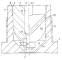
- the spray nozzle shown in the drawing has a housing 1 with an external thread 2 for screwing the spray nozzle into a feed line, not shown.
- the housing has a cylindrical inner wall 3, which merges into a conical inner wall 4, which leads to a first outlet opening 5.
- the housing 1 has an internal thread 7, into which a nozzle part 8 with its external thread 9 is screwed.
- a helical first channel 11 and further helical channels (not shown in the drawing) for supplying water are formed, which run around a swirl axis 12 symbolized by a dash-dotted line and tangentially into one between the nozzle part 8 and the vortex chamber 13 formed in the cylindrical inner wall 3 or the conical inner wall 4 of the housing.
- a second channel 14 for supplying water coaxial to the swirl axis 12 is formed in the nozzle part 8.
- the second channel 14 has a first cylindrical wall area 15, which merges via a conically narrowing wall area 16 into a second cylindrical wall area 17 of smaller cross-section, which leads to a cross-sectional constriction 18.
- a second conical wall area 19 of the second channel 14 which merges into a third cylindrical wall area 20.
- the third cylindrical wall area 20 leads to a second outlet opening 21.
Landscapes
- Health & Medical Sciences (AREA)
- Public Health (AREA)
- Business, Economics & Management (AREA)
- Emergency Management (AREA)
- Fire-Extinguishing By Fire Departments, And Fire-Extinguishing Equipment And Control Thereof (AREA)
- Nozzles (AREA)
Abstract
Description
- Die Erfindung betrifft eine Sprühdüse der im Oberbegriff des Anspruchs 1 genannten Art, insbesondere zum Versprühen von Wasser in Brandschutzanlagen.
- Sprühdüsen sind seit langem allgemein bekannt. Sie weisen wendelförmige enge Kanäle auf, die tangential in eine Wirbelkammer münden, die mit einer engen, koaxialen Düsenöffnung verbunden ist. Durch die wendelförmigen Kanäle wird das durchströmende flüssige Medium, z.B. Wasser, in Drehung versetzt. Auf dem radialen Weg nach innen zu der engen, koaxialen Düsenöffnung wird die Drehgeschwindigkeit beträchtlich erhöht, so daß das Wasser beim Austritt aus der Düsenöffnung durch die dann wirksamen Zentrifugalkräfte zu einem Sprühnebel aufgerissen wird, der sich im wesentlichen in Form eines Sprühkegels ausbreitet.
- Ein Nachteil dieser Sprühdüse besteht darin, daß im Inneren des Sprühkegels nur wenig Sprühnebel vorhanden ist, so daß sich dort, insbesondere im Zentrum des Sprühkegels, ein Bereich ausbildet, der nicht oder nur in erheblich verringertem Maße besprüht wird, so daß dort die Löschwirkung des Sprühnebels entsprechend gering ist.
- Aus der DD 141 626 ist eine Sprühdüse bekannt, die ein Gehäuse aufweist, in dem ein erstes Düsenteil angeordnet ist. Zwischen dem ersten Düsenteil und einer Innenwandung des Gehäuses ist eine erste Wirbelkammer gebildet, in die entfernt von der Wirbelachse ein an der Außenseite des ersten Düsenteiles gebildeter, wendelförmiger erster Kanal zur Zuführung von Wasser tangential mündet und die eine zu der Wirbelachse koaxiale erste Austrittsöffnung aufweist. Zwischen einer Innenwandung des ersten Düsenteiles und einem in dem ersten Düsenteil angeordneten zweiten Düsenteil ist eine zweite Wirbelkammer gebildet, in die entfernt von der Wirbelachse ein an der Außenseite des zweiten Düsenteiles gebildeter, wendelförmiger zweiter Kanal zur Zuführung von Wasser tangential mündet und die eine zu der Wirbelachse und zu der ersten Austrittsöffnung koaxiale zweite Austrittsöffnung aufweist. Bei Gebrauch der Sprühdüse strömt Wasser zum einen durch den wendelförmigen ersten Kanal zu der ersten Austrittsöffnung, so daß sich unter der Sprühdüse ein Sprühnebel in Form eines ersten Sprühkegels ausbildet. Zum anderen strömt Wasser durch den wendelförmigen zweiten Kanal zu der zweiten Austrittsöffnung, so daß sich unter der Sprühdüse ein Sprühnebel in Form eines zweiten Sprühkegels ausbildet. Der zweite Sprühkegel weist einen geringeren Öffnungswinkel als der erste Sprühkegel auf, so daß das Innere des ersten Sprühkegels durch den zweiten Sprühkegel mit Sprühnebel gefüllt ist und somit auch im Inneren des ersten Sprühkegels eine Löschwirkung erzielt ist.
- Ein Nachteil der bekannten Sprühdüse besteht darin, daß ihr Aufbau aufgrund des zur Erzeugung des zweiten Sprühkegels erforderlichen, in dem ersten Düsenteil angeordneten zweiten Düsenteil aufwendig ist, so daß die bekannte Sprühdüse teuer in der Herstellung ist.
- Beim Zusammenbau der bekannten Sprühdüse ist es erforderlich, zunächst das zweite Düsenteil in das erste Düsenteil einzuschrauben und anschließend das erste Düsenteil in das Gehäuse einzuschrauben. Es sind somit beim Zusammenbau viele Arbeitsschritte erforderlich. Dies ist zeitaufwendig, so daß die Herstellung der bekannten Sprühdüse weiter verteuert ist.
- Da das zweite Düsenteil im Inneren des ersten Düsenteiles angeordnet ist, sind seine Abmessungen gering, so daß auch der Querschnitt des an der Außenseite des zweiten Düsenteiles gebildeten zweiten Kanales entsprechend gering ist. Es besteht somit die Gefahr, daß sich der zweite Kanal durch Eindringen von Staub oder dergleichen in die Sprühdüse zusetzt. Dies hat zur Folge, daß sich der durch das zweite Düsenteil erzeugte zweite Sprühkegel nicht oder nur unvollständig ausbildet, so daß die Löschwirkung der Sprühdüse beeinträchtigt ist. Außerdem ist die Sprühweite der zweiten Wirbeldüse gering.
- Durch DD 245 825 A1 ist eine Sprühdüse aus einem Düsenhohlkörper mit einer Abrißphase von 120° an der Austrittsöffnung des Düsenkopfes bekannt, in dem ein Düseneinsatz mit äußeren Drallnuten und einer inneren Hohlschnecke eingefügt ist, wobei der Düseneinsatz im Düsenhohlkörper einen Spülraum offenläßt, in dem das Wasser in eine drehende Entspannungsphase mit gleichzeitigem Druckaufbau vor der Austrittsöffnung eintritt und nach Durchfluß durch die Austrittsöffnung sich ein Wasserkegel bildet, der an der Abrißphase des Düsenkopfes einen Abreißeffekt erzeugt und somit eine Verfeinerung des Sprühbildes durch Verkleinerung der Tröpfchengröße erzielt wird. Aufgrund der Rotation des Wassers in dem Spülraum reißt das Wasser an der Austrittsöffnung des Düsenkopfes zu einem Sprühkegel auf. Da alle Tröpfchen der dabei wirksamen Zentrifugalkraft unterliegen, bildet sich im Inneren des Sprühkegels ein kegeliger Raum, der im wesentlichen frei von Tröpfchen ist. Beim Auftreffen auf eine zu löschende Fläche wird somit nur ein Ring derselben besprüht, nicht dagegen sein Inneres. Dadurch ist die Löschwirkung dieser bekannten Wirbeldüse gering.
- Durch FR-473 630 ist eine Sprühdüse der betreffenden Art bekannt, bei der die Wirbelkammer trompetenförmig ausgebildet ist und in ihrem weiten Eingangsbereich durch eine Wand abgeschlossen ist, in der sich Schlitze befinden, durch die Wasser mit einer Geschwindigkeitskomponente in Umfangsrichtung in die Wirbelkammer eintritt. Dieses Wasser legt sich als Schicht an die Innenwandung der trompetenförmigen Wirbelkammer an und fließt entlang derselben zu dem sich verjüngenden Teil der Wirbelkammer, den es aufgrund der Geschwindigkeitsrotationskomponente als Sprühkegel verläßt.
- Im Zentrum der die trompetenförmige Wirbelkammer abschließenden Wandung befindet sich eine kurze Düse, aus der ein Wasserstrahl koaxial und gebündelt in die Wirbelkammer eintritt, wobei in dem größeren Teil der Wirbelkammer zwischen diesem zentralen Strahl und der entlang der Innenwandung der Wirbelkammer verlaufenden Strömung ein Hohlraum verbleibt. Dieser gebündelte Strahl durchläuft den verengten Teil der Wirbelkammer, wobei sich außerhalb dieses gebündelten Strahls die rotierende Strömung erstreckt. Durch Mitnahme wird der äußere Teil des gebündelten Strahls in Rotation versetzt, so daß seine Bestandteile beim Verlassen des verjüngten Teils der Wirbelkammer zu einem Sprühkegel aufgerissen werden, während der innere Teil des gebündelten Strahls die Wirbelkammer unbeeinflußt als Strahl verläßt. Dadurch ergibt sich ein Löschbild, in dem sich im Zentrum der gebündelte Strahl befindet, an den sich nach außen ein kegelförmiger Raum anschließt, der weitgehend frei von Sprühnebel ist, während sich außen wieder ein ringförmiger Sprühbereich erstreckt. Die Löschwirkung ist daher gering, und außerdem ergibt sich im Zentrum eine unerwünschte Konzentration von Löschwasser.
- Der Erfindung liegt die Aufgabe zugrunde, eine Sprühdüse der betreffenden Art anzugeben, die die Nachteile der bekannten Sprühdüse nicht aufweist, deren Aufbau vereinfacht ist, die kostengünstig herstellbar ist und bei der eine sichere Funktion gewährleistet ist.
- Diese Aufgabe wird durch die im Anspruch 1 angegebene Lehre gelöst.
- Der Grundgedanke der erfindungsgemäßen Lehre besteht darin, anstelle einer inneren zweiten Wirbeldüse einen zu der Wirbelachse der Wirbelkammer koaxialen zweiten Kanal vorzusehen und in Strömungsrichtung vor der zweiten Austrittsöffnung ein Druckgefälle zu erzeugen, so daß den zweiten Kanal durchströmendes Wasser beim Übergang in einen Bereich geringeren Druckes zu einem Sprühnebel aufgerissen wird.
- Der auf diese Weise erzeugte Sprühnebel breitet sich im Inneren des aus der Wirbelkammer austretenden Sprühkegels aus, so daß auch im Inneren dieses Sprühkegels die erwünschte Löschwirkung erzielt ist. Außerdem hat der aus der zweiten Austrittsöffnung austretende Sprühnebel eine größere Geschwindigkeit und damit eine größere Sprühweite.
- Der zweite Kanal kann durch eine sich in Längsrichtung des Düsenteiles erstreckende, durchgehende Ausnehmung gebildet sein, die auf einfache Weise erzeugbar ist. Die Herstellung der erfindungsgemäßen Sprühdüse ist somit einfach und damit kostengünstig.
- Gemäß einer Weiterbildung der Erfindung ist die Erweiterung in Strömungsrichtung gesehen nach einer Querschnittsverengung des zweiten Kanales gebildet. Bei dieser Ausführungsform ist durch die Querschnittsverengung und die daran anschließende Erweiterung eine Blende gebildet, an der sich ein hohes Druckgefälle ausbildet, so daß das Wasser besonders wirkungsvoll zu einem Sprühnebel aufgerissen wird.
- Gemäß einer anderen Weiterbildung ist die Erweiterung durch einen konischen Wandungsbereich des zweiten Kanales gebildet. Bei dieser Ausführungsform ist der zweite Kanal besonders einfach durch Erzeugung einer Bohrung mit abgestuftem Durchmesser erzeugbar. Dabei ist zweckmäßigerweise die Querschnittsverengung in Strömungsrichtung stufenweise abnehmend ausgebildet.
- Gemäß einer anderen Weiterbildung der Erfindung ist in dem Gehäuse ein Düsenteil angeordnet, an dessen Außenseite der erste Kanal und in dem zentrisch der zweite Kanal gebildet ist.
- Durch geeignete Dimensionierung des zweiten Kanales, insbesondere der Erweiterung und/oder der Querschnittsverengung, sind die Form und Tröpfchengröße des aus der zweiten Austrittsöffnung austretenden Sprühnebels in weiten Grenzen beeinflußbar, so daß die Sprühcharakteristik der erfindungsgemäßen Sprühdüse in weiten Grenzen beeinflußbar ist.
- Ferner ist die Sprühcharakteristik durch geeignete Wahl des Abstandes in Strömungsrichtung der ersten Austrittsöffnung von der zweiten Austrittsöffnung beeinflußbar. Dabei ist zweckmäßigerweise der Abstand der zweiten Austrittsöffnung von der ersten Austrittsöffnung einstellbar.
- Es ist auch möglich die Erweiterung und/oder die Querschnittsverengung verstellbar auszubilden.
- Anhand der Zeichnung soll die Erfindung an einem Ausführungsbeispiel näher erläutert werden.
- Die in der Zeichnung dargestellte Sprühdüse weist ein Gehäuse 1 mit einem Außengewinde 2 zum Einschrauben der Sprühdüse in eine nicht dargestellte Zuführleitung auf. Das Gehäuse weist eine zylindrische Innenwandung 3 auf, die in eine konische Innenwandung 4 übergeht, die zu einer ersten Austrittsöffnung 5 führt. An seinem zuführseitigen Ende 6 weist das Gehäuse 1 ein Innengewinde 7 auf, in das ein Düsenteil 8 mit seinem Außengewinde 9 eingeschraubt ist. In der Außenwandung 10 des Düsenteiles 8 sind ein wendelförmiger erster Kanal 11 und weitere, in der Zeichnung nicht dargestellte wendelförmige Kanäle zur Zuführung von Wasser gebildet, die um eine durch eine strichpunktierte Linie symbolisierte Wirbelachse 12 herum verlaufen und tangential in eine zwischen dem Düsenteil 8 und der zylindrischen Innenwandung 3 bzw. der konischen Innenwandung 4 des Gehäuses gebildete Wirbelkammer 13 münden. In dem Düsenteil 8 ist ein zu der Wirbelachse 12 koaxialer zweiter Kanal 14 zur Zuführung von Wasser gebildet. Der zweite Kanal 14 weist einen ersten zylindrischen Wandungsbereich 15 auf, der über einen sich konisch verengenden Wandungsbereich 16 in einen zweiten zylindrischen Wandungsbereich 17 geringeren Querschnittes übergeht, der zu einer Querschnittsverengung 18 führt. Im Anschluß an die Querschnittsverengung 18 ist eine Erweiterung durch einen zweiten konischen Wandungsbereich 19 des zweiten Kanales 14 gebildet, der in einen dritten zylindrischen Wandungsbereich 20 übergeht. Der dritte zylindrische Wandungsbereich 20 führt zu einer zweiten Austrittsöffnung 21.
- Bei Gebrauch der in der Zeichnung dargestellten Sprühdüse strömt Wasser einmal durch den wendelförmigen ersten Kanal 11 zu der ersten Austrittsöffnung 5. Durch den wendelförmigen Kanal 11 wird dem durchströmenden Wasser ein Drall aufgezwungen, dessen Geschwindigkeit sich zu der radial weiter innen liegenden ersten Austrittsöffnung 5 hin beträchtlich erhöht, so daß das Wasser beim Austritt aus der ersten Austrittsöffnung 5 zu einem Sprühnebel aufgerissen wird, der sich in Form eines Sprühkegels vor der Sprühdüse ausbreitet.
- Zum anderen strömt Wasser durch den zweiten Kanal 17. Nach Durchtritt des Wassers durch die Querschnittsverengung 18 sinkt der Wasserdruck im Bereich der durch die zweite konische Wandung 19 gebildeten Erweiterung ab. Im Bereich der Erweiterung ist somit eine Zone niedrigeren Druckes gebildet, so daß das durchströmende Wasser zu einem Sprühnebel aufgerissen wird, der durch die zweite Austrittsöffnung 21 austritt und sich im Inneren des aus der ersten Austrittsöffnung 5 austretenden Sprühkegels ausbreitet, so daß eine gleichmäßige Löschwirkung der Sprühdüse erzielt ist.
Claims (6)
- Sprühdüse, insbesondere zum Versprühen von Wasser in Brandschutzanlagen,mit einem Gehäuse,mit einer in dem Gehäuse angeordneten Wirbelkammer, in die entfernt von der Wirbelachse wenigstens ein erster Kanal zur Zuführung von Wasser im wesentlichen tangential mündet und die eine zu der Wirbelachse koaxiale erste Austrittsöffnung aufweist undmit einer innerhalb der Wirbelkammer angeordneten, zu der ersten Austrittsöffnung koaxialen zweiten Austrittsöffnung, die sich am Ende eines zur Wirbelachse (12) koaxialen zweiten Kanales (14) befindet,dadurch gekennzeichnet,
daß der zweite Kanal (14) vor der zweiten Austrittsöffnung (21) eine Erweiterung aufweist, deren zur Kanalachse senkrechte Querschnittsfläche in Strömungsrichtung zunimmt, daß die zur Kanalachse senkrechte Querschnittsfläche des zweiten Kanals (14) in Strömungsrichtung gesehen nach der Erweiterung nicht mehr abnimmt und daß die zweite Austrittsöffnung (21) in Strömungsrichtung gesehen so dicht vor der ersten Austrittsöffnung (5) angeordnet ist, daß der aus der zweiten Austrittsöffnung (21) austretende, durch den Unterdruck im Bereich der Erweiterung des zweiten Kanals (14) radial aufgerissene Strahl sich als Sprühnebel im Innern des aus der ersten Austrittsöffnung (5) austretenden Sprühkegels ausbreitet. - Sprühdüse nach Anspruch 1, dadurch gekennzeichnet, daß die Erweiterung in Strömungsrichtung gesehen nach einer Querschnittsverengung (16, 18) des zweiten Kanales (14) gebildet ist.
- Sprühdüse nach Anspruch 1, dadurch gekennzeichnet, daß die Erweiterung durch einen konischen Wandungsbereich (19) des zweiten Kanales (14) gebildet ist.
- Sprühdüse nach Anspruch 2, dadurch gekennzeichnet, daß die Querschnittsverengung (16, 18) in Strömungsrichtung stufenweise abnehmend ausgebildet ist.
- Sprühdüse nach Anspruch 1, dadurch gekennzeichnet, daß in dem Gehäuse (1) ein Düsenteil (8) angeordnet ist, an dessen Außenseite (10) der erste Kanal (11) und in dem zentrisch der zweite Kanal (14) gebildet ist.
- Sprühdüse nach Anspruch 1, dadurch gekennzeichnet, daß der Abstand der zweiten Austrittsöffnung (21) von der ersten Austrittsöffnung (5) einstellbar ist.
Priority Applications (5)
| Application Number | Priority Date | Filing Date | Title |
|---|---|---|---|
| DE4440681A DE4440681C2 (de) | 1994-11-15 | 1994-11-15 | Sprühdüse, insbesondere zum Versprühen von Wasser in Brandschutzanlagen |
| EP96106071A EP0801990B1 (de) | 1994-11-15 | 1996-04-18 | Sprühdüse, insbesondere zum Versprühen von Wasser in Brandschutzanlagen |
| DE59609407T DE59609407D1 (de) | 1996-04-18 | 1996-04-18 | Sprühdüse, insbesondere zum Versprühen von Wasser in Brandschutzanlagen |
| AT96106071T ATE219972T1 (de) | 1996-04-18 | 1996-04-18 | Sprühdüse, insbesondere zum versprühen von wasser in brandschutzanlagen |
| US08/635,599 US6129154A (en) | 1994-11-15 | 1996-04-22 | Spray nozzle, especially for spraying water in fire prevention systems |
Applications Claiming Priority (3)
| Application Number | Priority Date | Filing Date | Title |
|---|---|---|---|
| DE4440681A DE4440681C2 (de) | 1994-11-15 | 1994-11-15 | Sprühdüse, insbesondere zum Versprühen von Wasser in Brandschutzanlagen |
| EP96106071A EP0801990B1 (de) | 1994-11-15 | 1996-04-18 | Sprühdüse, insbesondere zum Versprühen von Wasser in Brandschutzanlagen |
| US08/635,599 US6129154A (en) | 1994-11-15 | 1996-04-22 | Spray nozzle, especially for spraying water in fire prevention systems |
Publications (2)
| Publication Number | Publication Date |
|---|---|
| EP0801990A1 true EP0801990A1 (de) | 1997-10-22 |
| EP0801990B1 EP0801990B1 (de) | 2002-07-03 |
Family
ID=27206962
Family Applications (1)
| Application Number | Title | Priority Date | Filing Date |
|---|---|---|---|
| EP96106071A Expired - Lifetime EP0801990B1 (de) | 1994-11-15 | 1996-04-18 | Sprühdüse, insbesondere zum Versprühen von Wasser in Brandschutzanlagen |
Country Status (3)
| Country | Link |
|---|---|
| US (1) | US6129154A (de) |
| EP (1) | EP0801990B1 (de) |
| DE (1) | DE4440681C2 (de) |
Cited By (2)
| Publication number | Priority date | Publication date | Assignee | Title |
|---|---|---|---|---|
| CN103987464A (zh) * | 2011-09-15 | 2014-08-13 | 宝洁公司 | 用于分配流体的喷雾嘴和包括此类喷雾嘴的喷涂器 |
| US12128118B2 (en) | 2021-07-29 | 2024-10-29 | The Procter & Gamble Company | Aerosol dispenser containing a hairspray composition and a nitrogen propellant |
Families Citing this family (14)
| Publication number | Priority date | Publication date | Assignee | Title |
|---|---|---|---|---|
| DE19608349A1 (de) * | 1996-03-05 | 1997-09-11 | Abb Research Ltd | Druckzerstäuberdüse |
| DE19713377A1 (de) | 1997-04-01 | 1998-10-15 | Siemens Ag | Düse, Verwendung einer Düse und Verfahren zur Eindüsung eines ersten Fluids in ein zweites Fluid |
| RU2159649C1 (ru) * | 2000-03-28 | 2000-11-27 | Общество с ограниченной ответственностью "ЮНИПАТ" | Спринклер (варианты) |
| KR100470762B1 (ko) * | 2002-02-08 | 2005-03-08 | 주식회사 윈 | 소화용 분사노즐 |
| GB2395660B (en) * | 2002-11-28 | 2006-09-06 | Kidde Ip Holdings Ltd | Fire extinguishant discharge method and apparatus |
| US20040256118A1 (en) * | 2002-11-28 | 2004-12-23 | Kidde-Fenwal Inc. | Fire extinguisher discharge method and apparatus |
| US20050011652A1 (en) * | 2003-07-17 | 2005-01-20 | Jinsong Hua | Spray head and nozzle arrangement for fire suppression |
| DE10349760A1 (de) * | 2003-10-24 | 2005-06-02 | Hemsing Sachverständigenbüro für Brandschutz GmbH | Löschdüsenträger |
| DE602004020445D1 (de) | 2004-04-08 | 2009-05-20 | Kidde Ip Holdings Ltd | Verfahren und Vorrichtung zum Sprühen eines Feuerlöschmittels |
| RU2264833C1 (ru) * | 2004-09-02 | 2005-11-27 | Долотказин Владимир Исмаилович | Распылитель жидкости и огнетушитель |
| FI116661B (fi) * | 2004-12-15 | 2006-01-31 | Marioff Corp Oy | Menetelmä väliaineen suihkuttamiseksi ja suihkutussuutin |
| WO2008036298A2 (en) * | 2006-09-19 | 2008-03-27 | Hypro, Llc | Spray head with covers |
| EP2623664B1 (de) | 2012-02-06 | 2019-10-02 | LG Electronics Inc. | Steuerungsverfahren für eine Waschmaschine mit einem Trocknungskanal aufweisend eine Düse |
| DE102019114868A1 (de) * | 2019-06-03 | 2020-12-03 | Minimax Viking Research & Development Gmbh | Sprühnebeldüse für Brandbekämpfungsanlagen, sowie Brandbekämpfungsanlagen selbiger |
Citations (6)
| Publication number | Priority date | Publication date | Assignee | Title |
|---|---|---|---|---|
| FR473630A (de) * | 1914-06-06 | 1915-01-19 | ||
| DE332438C (de) * | 1918-10-10 | 1921-01-31 | Basf Ag | Fluessigkeitsverteiler |
| GB285763A (en) * | 1927-10-25 | 1928-02-23 | George Fardell Glenny | Improvements in or relating to spraying nozzles |
| DE933235C (de) * | 1950-08-25 | 1955-09-22 | Otto Dipl-Ing Haessler | Zerstaeuberduese fuer Schaedlingsbekaempfungsspritzen |
| DE1604941B1 (de) * | 1965-12-16 | 1970-05-27 | Karlsruhe Augsburg Iweka | Zerstaeubungsduese in einem Zerstaeubungstrockner |
| DD245825A1 (de) * | 1986-02-10 | 1987-05-20 | Energieversorgung Ingbetrieb | Spruehduese zur bekaempfung von staub- glimmbraenden |
Family Cites Families (10)
| Publication number | Priority date | Publication date | Assignee | Title |
|---|---|---|---|---|
| DE141626C (de) * | ||||
| DE245825C (de) * | ||||
| US1395442A (en) * | 1918-12-18 | 1921-11-01 | Pyrene Mfg Co | Spray-nozzle |
| GB166515A (en) * | 1920-07-16 | 1922-11-30 | William Peyton Dunham | Improvements in the art of firing boilers by means of fuel oil |
| FR606356A (fr) * | 1925-10-08 | 1926-06-12 | Merlin Gerin | Armature de condensateur à haute tension |
| US2134347A (en) * | 1937-08-28 | 1938-10-25 | Spray Engineering Co | Play pipe construction |
| US2801881A (en) * | 1956-03-23 | 1957-08-06 | John F Campbell | Open orifice nozzle and valve |
| BE848456A (fr) * | 1976-11-17 | 1977-03-16 | Perfectionnements aux dispositifs gicleurs. | |
| DD141626A1 (de) * | 1979-03-27 | 1980-05-14 | Herzog Hans Joachim | Drallduese zur erzeugung von spruehnebeln |
| DD270664A1 (de) * | 1988-04-18 | 1989-08-09 | Univ Magdeburg Tech | Spruehduese mit bezueglich der fluessigkeitsverteilung gleichmaeszigem spruehbild |
-
1994
- 1994-11-15 DE DE4440681A patent/DE4440681C2/de not_active Expired - Fee Related
-
1996
- 1996-04-18 EP EP96106071A patent/EP0801990B1/de not_active Expired - Lifetime
- 1996-04-22 US US08/635,599 patent/US6129154A/en not_active Expired - Fee Related
Patent Citations (6)
| Publication number | Priority date | Publication date | Assignee | Title |
|---|---|---|---|---|
| FR473630A (de) * | 1914-06-06 | 1915-01-19 | ||
| DE332438C (de) * | 1918-10-10 | 1921-01-31 | Basf Ag | Fluessigkeitsverteiler |
| GB285763A (en) * | 1927-10-25 | 1928-02-23 | George Fardell Glenny | Improvements in or relating to spraying nozzles |
| DE933235C (de) * | 1950-08-25 | 1955-09-22 | Otto Dipl-Ing Haessler | Zerstaeuberduese fuer Schaedlingsbekaempfungsspritzen |
| DE1604941B1 (de) * | 1965-12-16 | 1970-05-27 | Karlsruhe Augsburg Iweka | Zerstaeubungsduese in einem Zerstaeubungstrockner |
| DD245825A1 (de) * | 1986-02-10 | 1987-05-20 | Energieversorgung Ingbetrieb | Spruehduese zur bekaempfung von staub- glimmbraenden |
Cited By (2)
| Publication number | Priority date | Publication date | Assignee | Title |
|---|---|---|---|---|
| CN103987464A (zh) * | 2011-09-15 | 2014-08-13 | 宝洁公司 | 用于分配流体的喷雾嘴和包括此类喷雾嘴的喷涂器 |
| US12128118B2 (en) | 2021-07-29 | 2024-10-29 | The Procter & Gamble Company | Aerosol dispenser containing a hairspray composition and a nitrogen propellant |
Also Published As
| Publication number | Publication date |
|---|---|
| DE4440681A1 (de) | 1996-05-30 |
| DE4440681C2 (de) | 1996-10-17 |
| US6129154A (en) | 2000-10-10 |
| EP0801990B1 (de) | 2002-07-03 |
Similar Documents
| Publication | Publication Date | Title |
|---|---|---|
| EP0604741B1 (de) | Dralldüse zum Zerstäuben einer Flüssigkeit | |
| DE3624939C2 (de) | ||
| DE4440681C2 (de) | Sprühdüse, insbesondere zum Versprühen von Wasser in Brandschutzanlagen | |
| DE3116660C2 (de) | Mehrstoff-Zerstäuberdüse | |
| EP1986788B1 (de) | Zweistoffdüse mit kreisförmig angeordneten sekundärluftdüsen | |
| DE112012005017B4 (de) | Vorrichtung zum Steuern einer Fluid-Strömung in einem Notfall-Waschsystem, Vorrichtung zum Steuern einer Fluid-Strömung und Waschsystem zum Liefern einer Fluid-Strömung | |
| DE2542240B2 (de) | Hohlkegeldüse zum Zerstäuben von Flüssigkeit | |
| EP0345670B1 (de) | Sprühkopf für Düsenfeuchter und Verfahren zum Befeuchten | |
| DE102011078857A1 (de) | Sprühdüse und Verfahren zum Erzeugen wenigstens eines rotierenden Sprühstrahls | |
| DE10361349B4 (de) | Kegeldüse | |
| DE2854639A1 (de) | Zerstaeubungseinrichtung | |
| EP0671216A2 (de) | Sprühdüse zur Erzeugung eines Doppel-Sprühnebel-Kegels | |
| DE68911144T2 (de) | Jet-sprühdüse. | |
| DE202016103825U1 (de) | Drallkörper sowie Kegeldüse mit einem solchen Drallkörper | |
| DE69913442T2 (de) | Flüssigkeits-Zerstäuber | |
| DE4407779C2 (de) | Sprühdüse zur Erzeugung von Sprühnebeln | |
| EP1201316B1 (de) | Hochrotationszerstäuber zur Aufbringung von Pulverlack | |
| DD293276A5 (de) | Vorrichtung zum reinigen von oberflaechen | |
| DE3309742C2 (de) | ||
| DE2757522B1 (de) | Rund- oder Ringstrahlduese zum Erzeugen und Abstrahlen eines Nebels oder Aerosols zur Beschichtung von Gegenstaenden | |
| DE3640818C1 (en) | Spray head for producing an air-liquid mixture, in particular for a cooling device | |
| DE3703075C2 (de) | ||
| DE19750068C1 (de) | Axial-Hohlkegeldüse zum Versprühen flüssiger Medien | |
| EP3088087A1 (de) | Sprühdüse und verfahren zum erzeugen von nicht runden sprühkegeln | |
| DE4108521C2 (de) | Strahlbrause |
Legal Events
| Date | Code | Title | Description |
|---|---|---|---|
| PUAI | Public reference made under article 153(3) epc to a published international application that has entered the european phase |
Free format text: ORIGINAL CODE: 0009012 |
|
| AK | Designated contracting states |
Kind code of ref document: A1 Designated state(s): AT BE CH DE DK FI FR GB IT LI NL SE |
|
| 17P | Request for examination filed |
Effective date: 19980129 |
|
| K1C1 | Correction of patent application (title page) published |
Effective date: 19971022 |
|
| RAP1 | Party data changed (applicant data changed or rights of an application transferred) |
Owner name: MINIMAX GMBH |
|
| 17Q | First examination report despatched |
Effective date: 19991201 |
|
| GRAG | Despatch of communication of intention to grant |
Free format text: ORIGINAL CODE: EPIDOS AGRA |
|
| GRAG | Despatch of communication of intention to grant |
Free format text: ORIGINAL CODE: EPIDOS AGRA |
|
| GRAH | Despatch of communication of intention to grant a patent |
Free format text: ORIGINAL CODE: EPIDOS IGRA |
|
| GRAH | Despatch of communication of intention to grant a patent |
Free format text: ORIGINAL CODE: EPIDOS IGRA |
|
| GRAA | (expected) grant |
Free format text: ORIGINAL CODE: 0009210 |
|
| AK | Designated contracting states |
Kind code of ref document: B1 Designated state(s): AT BE CH DE DK FI FR GB IT LI NL SE |
|
| PG25 | Lapsed in a contracting state [announced via postgrant information from national office to epo] |
Ref country code: IT Free format text: LAPSE BECAUSE OF FAILURE TO SUBMIT A TRANSLATION OF THE DESCRIPTION OR TO PAY THE FEE WITHIN THE PRESCRIBED TIME-LIMIT;WARNING: LAPSES OF ITALIAN PATENTS WITH EFFECTIVE DATE BEFORE 2007 MAY HAVE OCCURRED AT ANY TIME BEFORE 2007. THE CORRECT EFFECTIVE DATE MAY BE DIFFERENT FROM THE ONE RECORDED. Effective date: 20020703 Ref country code: GB Free format text: LAPSE BECAUSE OF FAILURE TO SUBMIT A TRANSLATION OF THE DESCRIPTION OR TO PAY THE FEE WITHIN THE PRESCRIBED TIME-LIMIT Effective date: 20020703 Ref country code: FR Free format text: LAPSE BECAUSE OF NON-PAYMENT OF DUE FEES Effective date: 20020703 Ref country code: FI Free format text: LAPSE BECAUSE OF FAILURE TO SUBMIT A TRANSLATION OF THE DESCRIPTION OR TO PAY THE FEE WITHIN THE PRESCRIBED TIME-LIMIT Effective date: 20020703 |
|
| REF | Corresponds to: |
Ref document number: 219972 Country of ref document: AT Date of ref document: 20020715 Kind code of ref document: T |
|
| REG | Reference to a national code |
Ref country code: CH Ref legal event code: EP |
|
| REF | Corresponds to: |
Ref document number: 59609407 Country of ref document: DE Date of ref document: 20020808 |
|
| PG25 | Lapsed in a contracting state [announced via postgrant information from national office to epo] |
Ref country code: SE Free format text: LAPSE BECAUSE OF FAILURE TO SUBMIT A TRANSLATION OF THE DESCRIPTION OR TO PAY THE FEE WITHIN THE PRESCRIBED TIME-LIMIT Effective date: 20021003 Ref country code: DK Free format text: LAPSE BECAUSE OF FAILURE TO SUBMIT A TRANSLATION OF THE DESCRIPTION OR TO PAY THE FEE WITHIN THE PRESCRIBED TIME-LIMIT Effective date: 20021003 |
|
| GBV | Gb: ep patent (uk) treated as always having been void in accordance with gb section 77(7)/1977 [no translation filed] |
Effective date: 20020703 |
|
| EN | Fr: translation not filed | ||
| PG25 | Lapsed in a contracting state [announced via postgrant information from national office to epo] |
Ref country code: BE Free format text: LAPSE BECAUSE OF NON-PAYMENT OF DUE FEES Effective date: 20030430 |
|
| PLBE | No opposition filed within time limit |
Free format text: ORIGINAL CODE: 0009261 |
|
| STAA | Information on the status of an ep patent application or granted ep patent |
Free format text: STATUS: NO OPPOSITION FILED WITHIN TIME LIMIT |
|
| 26N | No opposition filed |
Effective date: 20030404 |
|
| BERE | Be: lapsed |
Owner name: *MINIMAX G.M.B.H. Effective date: 20030430 |
|
| PGFP | Annual fee paid to national office [announced via postgrant information from national office to epo] |
Ref country code: AT Payment date: 20050308 Year of fee payment: 10 |
|
| PGFP | Annual fee paid to national office [announced via postgrant information from national office to epo] |
Ref country code: CH Payment date: 20050314 Year of fee payment: 10 |
|
| PGFP | Annual fee paid to national office [announced via postgrant information from national office to epo] |
Ref country code: NL Payment date: 20050316 Year of fee payment: 10 |
|
| REG | Reference to a national code |
Ref country code: CH Ref legal event code: PFA Owner name: MINIMAX GMBH & CO. KG Free format text: MINIMAX GMBH#INDUSTRIESTRASSE 10 - 12#23843 BAD OLDESLOE (DE) -TRANSFER TO- MINIMAX GMBH & CO. KG#INDUSTRIESTRASSE 10-12#23843 BAD OLDESLOE (DE) |
|
| PG25 | Lapsed in a contracting state [announced via postgrant information from national office to epo] |
Ref country code: AT Free format text: LAPSE BECAUSE OF NON-PAYMENT OF DUE FEES Effective date: 20060418 |
|
| PG25 | Lapsed in a contracting state [announced via postgrant information from national office to epo] |
Ref country code: LI Free format text: LAPSE BECAUSE OF NON-PAYMENT OF DUE FEES Effective date: 20060430 Ref country code: CH Free format text: LAPSE BECAUSE OF NON-PAYMENT OF DUE FEES Effective date: 20060430 |
|
| NLS | Nl: assignments of ep-patents |
Owner name: MIMX HOLDINGS GMBH & CO. KG Effective date: 20060307 Owner name: MINIMAX HOLDING GMBH Effective date: 20060307 |
|
| NLT1 | Nl: modifications of names registered in virtue of documents presented to the patent office pursuant to art. 16 a, paragraph 1 |
Owner name: MINIMAX GMBH & CO KG |
|
| PG25 | Lapsed in a contracting state [announced via postgrant information from national office to epo] |
Ref country code: NL Free format text: LAPSE BECAUSE OF NON-PAYMENT OF DUE FEES Effective date: 20061101 |
|
| REG | Reference to a national code |
Ref country code: CH Ref legal event code: PL |
|
| NLV4 | Nl: lapsed or anulled due to non-payment of the annual fee |
Effective date: 20061101 |
|
| PGFP | Annual fee paid to national office [announced via postgrant information from national office to epo] |
Ref country code: DE Payment date: 20090417 Year of fee payment: 14 |
|
| PG25 | Lapsed in a contracting state [announced via postgrant information from national office to epo] |
Ref country code: DE Free format text: LAPSE BECAUSE OF THE APPLICANT RENOUNCES Effective date: 20091224 |