EP0802037A2 - Pièce composite - Google Patents
Pièce composite Download PDFInfo
- Publication number
- EP0802037A2 EP0802037A2 EP97104984A EP97104984A EP0802037A2 EP 0802037 A2 EP0802037 A2 EP 0802037A2 EP 97104984 A EP97104984 A EP 97104984A EP 97104984 A EP97104984 A EP 97104984A EP 0802037 A2 EP0802037 A2 EP 0802037A2
- Authority
- EP
- European Patent Office
- Prior art keywords
- hub part
- composite component
- sealing
- die
- component according
- Prior art date
- Legal status (The legal status is an assumption and is not a legal conclusion. Google has not performed a legal analysis and makes no representation as to the accuracy of the status listed.)
- Granted
Links
- 239000002131 composite material Substances 0.000 title claims description 20
- 238000007789 sealing Methods 0.000 claims abstract description 43
- 238000005266 casting Methods 0.000 claims description 8
- 238000004512 die casting Methods 0.000 claims description 6
- 230000005540 biological transmission Effects 0.000 claims description 3
- 230000003014 reinforcing effect Effects 0.000 claims 1
- 238000000465 moulding Methods 0.000 abstract 2
- 238000009747 press moulding Methods 0.000 abstract 1
- 239000000463 material Substances 0.000 description 13
- 238000004519 manufacturing process Methods 0.000 description 5
- 229910052782 aluminium Inorganic materials 0.000 description 4
- XAGFODPZIPBFFR-UHFFFAOYSA-N aluminium Chemical compound [Al] XAGFODPZIPBFFR-UHFFFAOYSA-N 0.000 description 4
- 239000011324 bead Substances 0.000 description 4
- 238000001746 injection moulding Methods 0.000 description 4
- 230000002349 favourable effect Effects 0.000 description 3
- 230000001970 hydrokinetic effect Effects 0.000 description 3
- 239000000243 solution Substances 0.000 description 3
- 229910000831 Steel Inorganic materials 0.000 description 2
- 239000010959 steel Substances 0.000 description 2
- FYYHWMGAXLPEAU-UHFFFAOYSA-N Magnesium Chemical compound [Mg] FYYHWMGAXLPEAU-UHFFFAOYSA-N 0.000 description 1
- 229910000861 Mg alloy Inorganic materials 0.000 description 1
- 238000004873 anchoring Methods 0.000 description 1
- 230000015572 biosynthetic process Effects 0.000 description 1
- 238000010276 construction Methods 0.000 description 1
- 230000006378 damage Effects 0.000 description 1
- 230000003247 decreasing effect Effects 0.000 description 1
- 238000011161 development Methods 0.000 description 1
- 230000018109 developmental process Effects 0.000 description 1
- 230000000694 effects Effects 0.000 description 1
- 230000001939 inductive effect Effects 0.000 description 1
- 239000004413 injection moulding compound Substances 0.000 description 1
- 239000000314 lubricant Substances 0.000 description 1
- 238000003754 machining Methods 0.000 description 1
- 229910052749 magnesium Inorganic materials 0.000 description 1
- 239000011777 magnesium Substances 0.000 description 1
- 229910001092 metal group alloy Inorganic materials 0.000 description 1
- 238000005457 optimization Methods 0.000 description 1
- 230000002028 premature Effects 0.000 description 1
- 238000003825 pressing Methods 0.000 description 1
- 239000007779 soft material Substances 0.000 description 1
- 230000007704 transition Effects 0.000 description 1
Images


Classifications
-
- B—PERFORMING OPERATIONS; TRANSPORTING
- B29—WORKING OF PLASTICS; WORKING OF SUBSTANCES IN A PLASTIC STATE IN GENERAL
- B29C—SHAPING OR JOINING OF PLASTICS; SHAPING OF MATERIAL IN A PLASTIC STATE, NOT OTHERWISE PROVIDED FOR; AFTER-TREATMENT OF THE SHAPED PRODUCTS, e.g. REPAIRING
- B29C33/00—Moulds or cores; Details thereof or accessories therefor
- B29C33/0038—Moulds or cores; Details thereof or accessories therefor with sealing means or the like
-
- B—PERFORMING OPERATIONS; TRANSPORTING
- B22—CASTING; POWDER METALLURGY
- B22D—CASTING OF METALS; CASTING OF OTHER SUBSTANCES BY THE SAME PROCESSES OR DEVICES
- B22D19/00—Casting in, on, or around objects which form part of the product
-
- B—PERFORMING OPERATIONS; TRANSPORTING
- B29—WORKING OF PLASTICS; WORKING OF SUBSTANCES IN A PLASTIC STATE IN GENERAL
- B29C—SHAPING OR JOINING OF PLASTICS; SHAPING OF MATERIAL IN A PLASTIC STATE, NOT OTHERWISE PROVIDED FOR; AFTER-TREATMENT OF THE SHAPED PRODUCTS, e.g. REPAIRING
- B29C70/00—Shaping composites, i.e. plastics material comprising reinforcements, fillers or preformed parts, e.g. inserts
- B29C70/68—Shaping composites, i.e. plastics material comprising reinforcements, fillers or preformed parts, e.g. inserts by incorporating or moulding on preformed parts, e.g. inserts or layers, e.g. foam blocks
- B29C70/74—Moulding material on a relatively small portion of the preformed part, e.g. outsert moulding
-
- B—PERFORMING OPERATIONS; TRANSPORTING
- B29—WORKING OF PLASTICS; WORKING OF SUBSTANCES IN A PLASTIC STATE IN GENERAL
- B29C—SHAPING OR JOINING OF PLASTICS; SHAPING OF MATERIAL IN A PLASTIC STATE, NOT OTHERWISE PROVIDED FOR; AFTER-TREATMENT OF THE SHAPED PRODUCTS, e.g. REPAIRING
- B29C70/00—Shaping composites, i.e. plastics material comprising reinforcements, fillers or preformed parts, e.g. inserts
- B29C70/68—Shaping composites, i.e. plastics material comprising reinforcements, fillers or preformed parts, e.g. inserts by incorporating or moulding on preformed parts, e.g. inserts or layers, e.g. foam blocks
- B29C70/78—Moulding material on one side only of the preformed part
-
- F—MECHANICAL ENGINEERING; LIGHTING; HEATING; WEAPONS; BLASTING
- F16—ENGINEERING ELEMENTS AND UNITS; GENERAL MEASURES FOR PRODUCING AND MAINTAINING EFFECTIVE FUNCTIONING OF MACHINES OR INSTALLATIONS; THERMAL INSULATION IN GENERAL
- F16H—GEARING
- F16H41/00—Rotary fluid gearing of the hydrokinetic type
- F16H41/24—Details
- F16H2041/246—Details relating to one way clutch of the stator
-
- Y—GENERAL TAGGING OF NEW TECHNOLOGICAL DEVELOPMENTS; GENERAL TAGGING OF CROSS-SECTIONAL TECHNOLOGIES SPANNING OVER SEVERAL SECTIONS OF THE IPC; TECHNICAL SUBJECTS COVERED BY FORMER USPC CROSS-REFERENCE ART COLLECTIONS [XRACs] AND DIGESTS
- Y10—TECHNICAL SUBJECTS COVERED BY FORMER USPC
- Y10T—TECHNICAL SUBJECTS COVERED BY FORMER US CLASSIFICATION
- Y10T428/00—Stock material or miscellaneous articles
- Y10T428/12—All metal or with adjacent metals
- Y10T428/12014—All metal or with adjacent metals having metal particles
- Y10T428/12028—Composite; i.e., plural, adjacent, spatially distinct metal components [e.g., layers, etc.]
-
- Y—GENERAL TAGGING OF NEW TECHNOLOGICAL DEVELOPMENTS; GENERAL TAGGING OF CROSS-SECTIONAL TECHNOLOGIES SPANNING OVER SEVERAL SECTIONS OF THE IPC; TECHNICAL SUBJECTS COVERED BY FORMER USPC CROSS-REFERENCE ART COLLECTIONS [XRACs] AND DIGESTS
- Y10—TECHNICAL SUBJECTS COVERED BY FORMER USPC
- Y10T—TECHNICAL SUBJECTS COVERED BY FORMER US CLASSIFICATION
- Y10T428/00—Stock material or miscellaneous articles
- Y10T428/12—All metal or with adjacent metals
- Y10T428/12306—Workpiece of parallel, nonfastened components [e.g., fagot, pile, etc.]
- Y10T428/12313—Arranged to avoid lateral displacement
-
- Y—GENERAL TAGGING OF NEW TECHNOLOGICAL DEVELOPMENTS; GENERAL TAGGING OF CROSS-SECTIONAL TECHNOLOGIES SPANNING OVER SEVERAL SECTIONS OF THE IPC; TECHNICAL SUBJECTS COVERED BY FORMER USPC CROSS-REFERENCE ART COLLECTIONS [XRACs] AND DIGESTS
- Y10—TECHNICAL SUBJECTS COVERED BY FORMER USPC
- Y10T—TECHNICAL SUBJECTS COVERED BY FORMER US CLASSIFICATION
- Y10T428/00—Stock material or miscellaneous articles
- Y10T428/12—All metal or with adjacent metals
- Y10T428/12306—Workpiece of parallel, nonfastened components [e.g., fagot, pile, etc.]
- Y10T428/12319—Composite
-
- Y—GENERAL TAGGING OF NEW TECHNOLOGICAL DEVELOPMENTS; GENERAL TAGGING OF CROSS-SECTIONAL TECHNOLOGIES SPANNING OVER SEVERAL SECTIONS OF THE IPC; TECHNICAL SUBJECTS COVERED BY FORMER USPC CROSS-REFERENCE ART COLLECTIONS [XRACs] AND DIGESTS
- Y10—TECHNICAL SUBJECTS COVERED BY FORMER USPC
- Y10T—TECHNICAL SUBJECTS COVERED BY FORMER US CLASSIFICATION
- Y10T428/00—Stock material or miscellaneous articles
- Y10T428/12—All metal or with adjacent metals
- Y10T428/12493—Composite; i.e., plural, adjacent, spatially distinct metal components [e.g., layers, joint, etc.]
-
- Y—GENERAL TAGGING OF NEW TECHNOLOGICAL DEVELOPMENTS; GENERAL TAGGING OF CROSS-SECTIONAL TECHNOLOGIES SPANNING OVER SEVERAL SECTIONS OF THE IPC; TECHNICAL SUBJECTS COVERED BY FORMER USPC CROSS-REFERENCE ART COLLECTIONS [XRACs] AND DIGESTS
- Y10—TECHNICAL SUBJECTS COVERED BY FORMER USPC
- Y10T—TECHNICAL SUBJECTS COVERED BY FORMER US CLASSIFICATION
- Y10T428/00—Stock material or miscellaneous articles
- Y10T428/24—Structurally defined web or sheet [e.g., overall dimension, etc.]
- Y10T428/24777—Edge feature
-
- Y—GENERAL TAGGING OF NEW TECHNOLOGICAL DEVELOPMENTS; GENERAL TAGGING OF CROSS-SECTIONAL TECHNOLOGIES SPANNING OVER SEVERAL SECTIONS OF THE IPC; TECHNICAL SUBJECTS COVERED BY FORMER USPC CROSS-REFERENCE ART COLLECTIONS [XRACs] AND DIGESTS
- Y10—TECHNICAL SUBJECTS COVERED BY FORMER USPC
- Y10T—TECHNICAL SUBJECTS COVERED BY FORMER US CLASSIFICATION
- Y10T428/00—Stock material or miscellaneous articles
- Y10T428/24—Structurally defined web or sheet [e.g., overall dimension, etc.]
- Y10T428/24942—Structurally defined web or sheet [e.g., overall dimension, etc.] including components having same physical characteristic in differing degree
- Y10T428/24983—Hardness
-
- Y—GENERAL TAGGING OF NEW TECHNOLOGICAL DEVELOPMENTS; GENERAL TAGGING OF CROSS-SECTIONAL TECHNOLOGIES SPANNING OVER SEVERAL SECTIONS OF THE IPC; TECHNICAL SUBJECTS COVERED BY FORMER USPC CROSS-REFERENCE ART COLLECTIONS [XRACs] AND DIGESTS
- Y10—TECHNICAL SUBJECTS COVERED BY FORMER USPC
- Y10T—TECHNICAL SUBJECTS COVERED BY FORMER US CLASSIFICATION
- Y10T428/00—Stock material or miscellaneous articles
- Y10T428/249921—Web or sheet containing structurally defined element or component
- Y10T428/249923—Including interlaminar mechanical fastener
Definitions
- the invention relates to a composite component according to the preamble of claim 1.
- Such a composite component is known, inter alia, from US Pat. No. 5,094,076.
- This composite component has a hub part which is surrounded by a plastic component produced by injection molding.
- the plastic component is cast on during manufacture, a transmission cone having stops for sealing plates which are intended to prevent the injection molding compound from getting into the inner region of the hub part.
- the disadvantage here is that separate sealing plates are required which have to withstand the injection molding pressure.
- a die-cast part is to be made from aluminum, for example, an injection molding pressure of 400 to 600 bar is required, which would require a correspondingly strong design of sealing plates.
- Another disadvantage of the known solution is that the closed design of the composite component hermetically seals the roller freewheel clutch provided in the hub part, so that relubrication is not possible without destruction and, in particular, it is not possible to connect the roller freewheel clutch to the lubricant circuit of a hydrokinetic torque converter. Furthermore, the additional arrangement of the sealing plates requires precise adjustment, which is to be achieved with a special cone, in order to prevent the occurrence of an imbalance.
- the sealing plate according to US Pat. No. 5,094,076 can be produced from comparatively soft material and therefore suitable for sealing purposes.
- the sealing effect as a whole is rather unsatisfactory, since an additional sealing point is practically created due to the additional component and the function of the sealing plate depends very much on the exact machining of the hub part or the uniform pressing force via the stops of the cone there.
- the invention has for its object to provide a composite component according to the preamble of claim 1, which despite the wear resistance of the hub part enables a secure seal when molded or cast on the die-cast part.
- the manufacture of a composite component according to the invention surprisingly enables the hub part to be securely sealed off from the die casting mold, despite the enormous pressure when the die casting material such as magnesium or aluminum or other suitable light metal alloys is shot in.
- the sealing projection according to the invention can be deformed by a corresponding closing force of the mold, the deformation being able to take place both elastically and plastically and preferably being partly plastically and partly elastically.
- this measure can also be used when a roller one-way clutch, which has the hub part, requires very hard work surfaces. These are hardened without further ado, so that the hub part has an increased hardness only in those areas where this is necessary.
- the sealing projections are preferably designed as ring-shaped sealing lips and thus extend in a circular manner on opposite end faces of the hub part. Due to the closing force of the mold, centering and optimization of the sealing contact between the molds, that is to say in particular the mold halves, and the hub part takes place practically automatically. The required sealing force for the mold is not increased by the sealing projections according to the invention.
- the hub part is designed as an outer race of a roller one-way clutch for a stator of a hydrokinetic torque converter and, starting from a conical chamfer, has ring beads or sealing projections with a sawtooth or triangular cross section on its axial end faces.
- the hub part is in the form of the outer race of a roller one-way clutch on it Provide the radial outer circumference with a number of radially projecting surface projections, which reinforce the cross-section at risk of breakage in the region of the recesses for the rollers of the roller one-way clutch.
- the sealing projection is provided adjacent to a conical inclined surface.
- the tapered cross-sectional area towards the sealing projection practically turns the conical surface into a kind of impact surface, so that no particularly high dynamic pressure is applied to the seal.
- the sealing projection or annular bead can have any suitable structure that is suitable for the formation of a seal with generation of a deformation.
- the sealing projection can have an essentially sawtooth-shaped cross section with preferably rounded tips.
- the excess of the unloaded sealing projection compared to the molds can be adapted to the requirements in a wide range.
- the excess is preferably chosen so that at least a significant part of, for example, 20% of the closing force, which can be, for example, approximately 10 GN (1000 t), is collected via the sealing projection and used as a sealing force.
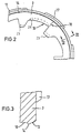
- FIG. 1 shows a composite component 1 according to the invention in a radial section. It consists of a hub part 2 made of a harder material and a die-cast part 3 made of lighter and / or softer material.
- the hub part 2 here forms the outer race of a roller one-way clutch 4, the further components of which, such as the inner race 5 and the rollers 6, are only indicated in dash-dotted lines.
- sealing projections 13 and 14 formed with a substantially triangular cross-section, which can be acted upon directly by the mold halves.
- the inclined surfaces 11 and 12 extend at an angle of approximately 65 ° to an axis 22 of the hub part 2.
- the hub part 2 which in the present case forms the outer race of a roller freewheel clutch, consists of steel and is hardened on its inner cam contour 15, specifically on the working areas 23 and 24.
- the hardening is preferably carried out before the die-cast part 3 is cast on, the hardening depth being adaptable to the requirements over a wide range and preferably about 2 mm for the working area 24 for guiding the rollers 6 of the roller freewheel clutch and about 3 mm in the working area 23 for the Bearing of the inner race 5 is.
- the steel material remains unhardened, so that it can be plastically deformed by the very high closing pressure of the mold halves 7 and 8 and thus ensures a reliable seal.
- the cam contour 15 on the outer race 2 of a roller freewheel clutch leads to a cross-section at risk of breakage in the area of the arrow 16.
- this cross-section at risk of breakage can be favorably be reinforced.
- the surface projections 17 ensure a more favorable anchoring of the die-cast part on the hub part in order to reliably transmit the torques occurring on the die-cast part to the hub part 2.
- An aluminum or a magnesium alloy or also corresponding plastic materials can preferably be used for the die-cast part.
- the hub part is pressurized in a ring by die casting. After the mold has cooled, there is accordingly an expansion due to the decreasing injection molding pressure, which can be, for example, 1/20 mm. In order to compensate for this change in diameter, either a hub part 2 with a correspondingly adapted diameter can be used from the beginning, or regrinding takes place.
- the materials to be used can always be optimally adapted in terms of their weight / strength ratio by direct casting on by means of the sealing lips or sealing projections 13 and 14 according to the invention, despite the intended use of hardened working areas 23 and 24.
- the hardening can also be carried out only after the casting process has been completed, inductive hardening being preferred in this connection. It is understood that regrinding may be required with such a solution.
- a radius 20 is formed on the crest of the sealing projection 14. Compared to a sawtooth-shaped construction of the sealing projection 14, this configuration allows a somewhat reduced surface pressure and a somewhat higher tolerance to manufacturing-related manufacturing tolerances.
- an inner radius 21 is provided in the region of the transition to the end face 10.
- the entire area of the hub part 2 shown in FIG. 4 is unhardened, in contrast to the work surfaces or areas 23 and 24, which are shown in Fig. 2.
- the invention is not limited to use in connection with a roller one-way clutch. Basically, it is suitable for any use in the drive train with rotating parts that are used for power transmission, the highest forces to be transmitted being routed to the hub or, if applicable, the shaft clamped there.
- the solution according to the invention can also be used in other composite components, in which hard and thus low-wear working areas are required despite the casting of a part made of a lighter material.
Landscapes
- Engineering & Computer Science (AREA)
- Mechanical Engineering (AREA)
- Chemical & Material Sciences (AREA)
- Composite Materials (AREA)
- Mechanical Operated Clutches (AREA)
- Moulds For Moulding Plastics Or The Like (AREA)
- Injection Moulding Of Plastics Or The Like (AREA)
Applications Claiming Priority (4)
| Application Number | Priority Date | Filing Date | Title |
|---|---|---|---|
| DE19615783 | 1996-04-20 | ||
| DE19615783 | 1996-04-20 | ||
| DE19626974A DE19626974A1 (de) | 1996-04-20 | 1996-07-04 | Verbundbauteil |
| DE19626974 | 1996-07-04 |
Publications (3)
| Publication Number | Publication Date |
|---|---|
| EP0802037A2 true EP0802037A2 (fr) | 1997-10-22 |
| EP0802037A3 EP0802037A3 (fr) | 1999-01-13 |
| EP0802037B1 EP0802037B1 (fr) | 2001-10-10 |
Family
ID=26024971
Family Applications (1)
| Application Number | Title | Priority Date | Filing Date |
|---|---|---|---|
| EP97104984A Expired - Lifetime EP0802037B1 (fr) | 1996-04-20 | 1997-03-24 | Pièce composite |
Country Status (3)
| Country | Link |
|---|---|
| US (1) | US6093478A (fr) |
| EP (1) | EP0802037B1 (fr) |
| JP (1) | JPH1071621A (fr) |
Families Citing this family (8)
| Publication number | Priority date | Publication date | Assignee | Title |
|---|---|---|---|---|
| DE10011237C2 (de) | 2000-03-08 | 2002-09-12 | Borgwarner Inc | Baugruppe mit Freilauf und Leitrad eines hydrodynamischen Wandlers |
| US20040182670A1 (en) * | 2002-07-02 | 2004-09-23 | Hiromi Nojiri | Rotation transmission device |
| DE10231608A1 (de) * | 2002-07-12 | 2004-01-29 | Daimlerchrysler Ag | Hydrodynamischer Drehmomentwandler mit einem Leitrad und Herstellungsverfahren für ein solches |
| US7526565B2 (en) * | 2003-04-03 | 2009-04-28 | International Business Machines Corporation | Multiple description hinting and switching for adaptive media services |
| DE502006000813D1 (de) * | 2005-04-20 | 2008-07-10 | Luk Lamellen & Kupplungsbau | Hydrodynamischer Drehmomentwandler |
| JP2008213393A (ja) * | 2007-03-07 | 2008-09-18 | Jtekt Corp | 樹脂巻き部品 |
| JP5507408B2 (ja) * | 2010-10-18 | 2014-05-28 | 小島プレス工業株式会社 | カウルルーバー用シール構造 |
| US10550893B2 (en) * | 2017-04-19 | 2020-02-04 | Seiko Instruments Inc. | Rolling bearing |
Family Cites Families (5)
| Publication number | Priority date | Publication date | Assignee | Title |
|---|---|---|---|---|
| DE1207603B (de) * | 1961-02-11 | 1965-12-23 | Friedrich Stuebbe | Verfahren zum Herstellen von Kuekenhaehnen |
| US4296063A (en) * | 1979-09-12 | 1981-10-20 | Mitsubishi Denki Kabushiki Kaisha | Method of producing bracket and gear box of electric motor with gear _box and metal mold used with the same |
| DE3339355C3 (de) * | 1983-10-29 | 1994-08-11 | Skf Gmbh | Rolle und Vorrichtung zu deren Herstellung |
| JPS63141712A (ja) * | 1986-12-03 | 1988-06-14 | Nippon Columbia Co Ltd | プラスチツクの射出成形方法 |
| US5094076A (en) * | 1990-11-16 | 1992-03-10 | Maclean-Fogg Company | Torque converter reactor assembly and method |
-
1997
- 1997-03-24 EP EP97104984A patent/EP0802037B1/fr not_active Expired - Lifetime
- 1997-04-18 US US08/844,710 patent/US6093478A/en not_active Expired - Fee Related
- 1997-04-19 JP JP11655897A patent/JPH1071621A/ja active Pending
Also Published As
| Publication number | Publication date |
|---|---|
| EP0802037B1 (fr) | 2001-10-10 |
| JPH1071621A (ja) | 1998-03-17 |
| US6093478A (en) | 2000-07-25 |
| EP0802037A3 (fr) | 1999-01-13 |
Similar Documents
| Publication | Publication Date | Title |
|---|---|---|
| DE112008002486B4 (de) | Lagerungsvorrichtung für Rad und Achsenmodul | |
| DE69414758T2 (de) | Zusammensetzter Verbundstoff und Verfahren zu seiner Herstellung | |
| EP0278292B1 (fr) | Arbre creux et son procédé de fabrication | |
| EP2032877A2 (fr) | Roue conique | |
| DE1627594A1 (de) | Reibungsschweissverfahren und reibungsgeschweisste Antriebswelle oder Antriebsachse | |
| DE10301057A1 (de) | Rotator mit Lager und Verfahren zu seiner Herstellung | |
| EP1872024B1 (fr) | Denture frontale d'un element de couplage destinee a la transmission de couples | |
| WO2007144301A1 (fr) | Arbre avec un composant fixe | |
| DE19830593C1 (de) | Kugelgelenk und Verfahren zu dessen Herstellung | |
| EP0802037B1 (fr) | Pièce composite | |
| EP0176688B1 (fr) | Rondelle de retenu-ressort de soupape et sa méthode de fabrication | |
| DE3037763A1 (de) | Metallrand-oeldichtung | |
| EP2242938A1 (fr) | Raccord élastique en rotation et procédé de fabrication de celui-ci | |
| DE19626974A1 (de) | Verbundbauteil | |
| EP2255977A2 (fr) | Procédé d'imprégnation d'une dentelure frontale | |
| DE102006059946A1 (de) | Zahnriemenrad | |
| EP0690956B1 (fr) | Procede de fabrication d'un couvercle coule en metal leger et couvercle ainsi obtenu | |
| AT526440B1 (de) | Verfahren zur Herstellung einer Antriebskomponente | |
| DE10220419A1 (de) | Zylinderrollenlager | |
| EP1884687A1 (fr) | Poulie à câble | |
| EP3346163B1 (fr) | Roue dentée ainsi que systeme formant roue dentée d'un moteur a combustion interne | |
| DE102020200153A1 (de) | Verfahren zur Bearbeitung einer Ringnut | |
| DE102011120596A1 (de) | Kolben für eine doppeltwirkende Kolben-Zylinder-Einheit und hydraulische Servolenkung mit einem solchen Kolben | |
| DE10231608A1 (de) | Hydrodynamischer Drehmomentwandler mit einem Leitrad und Herstellungsverfahren für ein solches | |
| DE19636565C2 (de) | Verfahren und Ausgangswerkstück zum Herstellen eines topfförmigen Werkstücks |
Legal Events
| Date | Code | Title | Description |
|---|---|---|---|
| PUAI | Public reference made under article 153(3) epc to a published international application that has entered the european phase |
Free format text: ORIGINAL CODE: 0009012 |
|
| AK | Designated contracting states |
Kind code of ref document: A2 Designated state(s): DE FR GB |
|
| PUAL | Search report despatched |
Free format text: ORIGINAL CODE: 0009013 |
|
| AK | Designated contracting states |
Kind code of ref document: A3 Designated state(s): DE FR GB |
|
| 17P | Request for examination filed |
Effective date: 19990204 |
|
| 17Q | First examination report despatched |
Effective date: 19990602 |
|
| RAP1 | Party data changed (applicant data changed or rights of an application transferred) |
Owner name: FORD-WERKE AKTIENGESELLSCHAFT Owner name: GEORG FISCHER MOESSNER GMBH |
|
| GRAG | Despatch of communication of intention to grant |
Free format text: ORIGINAL CODE: EPIDOS AGRA |
|
| GRAG | Despatch of communication of intention to grant |
Free format text: ORIGINAL CODE: EPIDOS AGRA |
|
| GRAH | Despatch of communication of intention to grant a patent |
Free format text: ORIGINAL CODE: EPIDOS IGRA |
|
| GRAH | Despatch of communication of intention to grant a patent |
Free format text: ORIGINAL CODE: EPIDOS IGRA |
|
| GRAA | (expected) grant |
Free format text: ORIGINAL CODE: 0009210 |
|
| AK | Designated contracting states |
Kind code of ref document: B1 Designated state(s): DE FR GB |
|
| REF | Corresponds to: |
Ref document number: 59704829 Country of ref document: DE Date of ref document: 20011115 |
|
| REG | Reference to a national code |
Ref country code: GB Ref legal event code: IF02 |
|
| ET | Fr: translation filed | ||
| GBT | Gb: translation of ep patent filed (gb section 77(6)(a)/1977) |
Effective date: 20020213 |
|
| PLBE | No opposition filed within time limit |
Free format text: ORIGINAL CODE: 0009261 |
|
| STAA | Information on the status of an ep patent application or granted ep patent |
Free format text: STATUS: NO OPPOSITION FILED WITHIN TIME LIMIT |
|
| 26N | No opposition filed | ||
| PGFP | Annual fee paid to national office [announced via postgrant information from national office to epo] |
Ref country code: DE Payment date: 20030110 Year of fee payment: 7 |
|
| PGFP | Annual fee paid to national office [announced via postgrant information from national office to epo] |
Ref country code: GB Payment date: 20030226 Year of fee payment: 7 |
|
| PGFP | Annual fee paid to national office [announced via postgrant information from national office to epo] |
Ref country code: FR Payment date: 20030326 Year of fee payment: 7 |
|
| PG25 | Lapsed in a contracting state [announced via postgrant information from national office to epo] |
Ref country code: GB Free format text: LAPSE BECAUSE OF NON-PAYMENT OF DUE FEES Effective date: 20040324 |
|
| PG25 | Lapsed in a contracting state [announced via postgrant information from national office to epo] |
Ref country code: DE Free format text: LAPSE BECAUSE OF NON-PAYMENT OF DUE FEES Effective date: 20041001 |
|
| GBPC | Gb: european patent ceased through non-payment of renewal fee |
Effective date: 20040324 |
|
| PG25 | Lapsed in a contracting state [announced via postgrant information from national office to epo] |
Ref country code: FR Free format text: LAPSE BECAUSE OF NON-PAYMENT OF DUE FEES Effective date: 20041130 |
|
| REG | Reference to a national code |
Ref country code: FR Ref legal event code: ST |