EP0802075A2 - Châssis auxiliaire - Google Patents
Châssis auxiliaire Download PDFInfo
- Publication number
- EP0802075A2 EP0802075A2 EP97104926A EP97104926A EP0802075A2 EP 0802075 A2 EP0802075 A2 EP 0802075A2 EP 97104926 A EP97104926 A EP 97104926A EP 97104926 A EP97104926 A EP 97104926A EP 0802075 A2 EP0802075 A2 EP 0802075A2
- Authority
- EP
- European Patent Office
- Prior art keywords
- bearing
- elastic
- bearings
- auxiliary frame
- frame according
- Prior art date
- Legal status (The legal status is an assumption and is not a legal conclusion. Google has not performed a legal analysis and makes no representation as to the accuracy of the status listed.)
- Granted
Links
Images


Classifications
-
- B—PERFORMING OPERATIONS; TRANSPORTING
- B60—VEHICLES IN GENERAL
- B60G—VEHICLE SUSPENSION ARRANGEMENTS
- B60G3/00—Resilient suspensions for a single wheel
- B60G3/18—Resilient suspensions for a single wheel with two or more pivoted arms, e.g. parallelogram
- B60G3/20—Resilient suspensions for a single wheel with two or more pivoted arms, e.g. parallelogram all arms being rigid
-
- B—PERFORMING OPERATIONS; TRANSPORTING
- B60—VEHICLES IN GENERAL
- B60G—VEHICLE SUSPENSION ARRANGEMENTS
- B60G7/00—Pivoted suspension arms; Accessories thereof
- B60G7/02—Attaching arms to sprung part of vehicle
-
- B—PERFORMING OPERATIONS; TRANSPORTING
- B62—LAND VEHICLES FOR TRAVELLING OTHERWISE THAN ON RAILS
- B62D—MOTOR VEHICLES; TRAILERS
- B62D21/00—Understructures, i.e. chassis frame on which a vehicle body may be mounted
- B62D21/11—Understructures, i.e. chassis frame on which a vehicle body may be mounted with resilient means for suspension, e.g. of wheels or engine; sub-frames for mounting engine or suspensions
-
- B—PERFORMING OPERATIONS; TRANSPORTING
- B60—VEHICLES IN GENERAL
- B60G—VEHICLE SUSPENSION ARRANGEMENTS
- B60G2200/00—Indexing codes relating to suspension types
- B60G2200/10—Independent suspensions
- B60G2200/14—Independent suspensions with lateral arms
- B60G2200/144—Independent suspensions with lateral arms with two lateral arms forming a parallelogram
-
- B—PERFORMING OPERATIONS; TRANSPORTING
- B60—VEHICLES IN GENERAL
- B60G—VEHICLE SUSPENSION ARRANGEMENTS
- B60G2204/00—Indexing codes related to suspensions per se or to auxiliary parts
- B60G2204/10—Mounting of suspension elements
- B60G2204/15—Mounting of subframes
-
- B—PERFORMING OPERATIONS; TRANSPORTING
- B60—VEHICLES IN GENERAL
- B60G—VEHICLE SUSPENSION ARRANGEMENTS
- B60G2204/00—Indexing codes related to suspensions per se or to auxiliary parts
- B60G2204/40—Auxiliary suspension parts; Adjustment of suspensions
- B60G2204/44—Centering or positioning means
- B60G2204/4404—Retainers for holding a fixing element, e.g. bushing, nut, bolt etc., until it is tightly fixed in position
-
- B—PERFORMING OPERATIONS; TRANSPORTING
- B60—VEHICLES IN GENERAL
- B60G—VEHICLE SUSPENSION ARRANGEMENTS
- B60G2206/00—Indexing codes related to the manufacturing of suspensions: constructional features, the materials used, procedures or tools
- B60G2206/01—Constructional features of suspension elements, e.g. arms, dampers, springs
- B60G2206/60—Subframe construction
Definitions
- the invention relates to a subframe for the pivotable articulation of handlebar arms of a wheel suspension according to the preamble of claim 1.
- a side support for the pivotable arrangement of handlebar arms of a wheel suspension in a vehicle is known, which is attached to the vehicle body via two bearings. To mutually support the side beams, these are connected to one another via cross bridges.
- the object of the invention is to provide an improved subframe with two side supports which ensure stable support of the wheel suspension without mutual support when forces act on the wheel.
- the side supports for snapping from wheel forces no longer have any bridge-like supports, but a central bearing is provided above a rear and a front bearing. This center bearing is arranged at a defined distance from the other bearings, so that moments from forces can be effectively supported on the wheel.
- the side carrier advantageously consists of a U-shaped and upwardly open segment, which due to the arrangement of the bearings does not have to be designed as a closed box profile at the free ends of the segment legs, since the central bearing and a rear bearing provide immediate, stable support effect on the vehicle body.
- the elastic bearings in the side girders are in the form of elongated bearings in a vertical orientation with a rigid bearing sleeve and an elastic element arranged between this and a receptacle in the side part.
- the elastic element is preloaded axially on the vehicle body by means of a fastening screw.
- the elastic bearings are preferably held in so-called whistles which are formed on the side support and are arranged in a common vertical plane.
- bearing receptacles are provided for the handlebar arms, so that there is a stiff and stable support for the wheel suspension.
- the side supports are not connected to one another via cross members, and pivoting of the side supports about an axis running through front and rear bearings is thus avoided by the central bearing. This ensures that the moments from the wheel load and the side forces are only transmitted or supported by the elastic bearings.
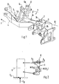
- An auxiliary frame for the pivotable mounting of wheel control arms of a wheel suspension essentially comprises two side supports 1, one side support being provided on each vehicle side or per vehicle wheel.
- the side carrier 1 consists of a U-shaped segment which is open at the top and has two segment legs 2, 3 and an elongated web part 4.
- the side member 1 is connected to the vehicle body via three elastic bearings 5, 6 and 7, which are received in receptacles 5a, 6a and 7a in the form of so-called whistles.
- the front bearing 5 and the rear bearing 7 are arranged on an inclined plane 10 with respect to the direction of travel F.
- the front bearing 5 is on the extended web part 4 and the two other bearings 6 and 7 are held at the free ends of the segment legs 2 and 3 in the receptacles 6a, 7a.
- the receptacle 6a of the central bearing 6 is formed on the leg 2 of the side support 1 at a distance a.
- the bearings 5, 6 and 7 or the bearing receptacles 5a, 6a and 7a are seen in plan view (FIG. 4) in a common vertical plane 12.
- the bearing receptacles 5a, 6a and 7a have adjacent storage locations 13, 14, 15 for the handlebar arms of the wheel suspension, so that a fixed, unchangeable local support for the wheel suspension is ensured.
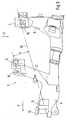
- the elastic bearings 5, 6 and 7 are designed with a length b so that cardanic movements can be largely eliminated during driving.
- the bearings 5, 6 and 7 comprise an elongated elastic sleeve element 16 which is held on a metal sleeve 17. Axial bracing in the receptacles 5a, 6a, 7a of the side carriers 1 takes place in each case via a screw 18 on the vehicle body 19.
- moments are generated in driving operation with forces acting on the wheel, such as lateral forces F S , wheel load forces F R , drive or braking forces, about the axis of each wheel side running through the front and rear bearings. So that these moments are supported can, without providing a cross member support between the side members, a raised center bearing 6 is provided on the side member 1, which causes an additional counterforce and the moment M is supported by F R and F S.
Landscapes
- Engineering & Computer Science (AREA)
- Mechanical Engineering (AREA)
- Chemical & Material Sciences (AREA)
- Combustion & Propulsion (AREA)
- Transportation (AREA)
- Vehicle Body Suspensions (AREA)
- Automatic Cycles, And Cycles In General (AREA)
- Arrangement Or Mounting Of Propulsion Units For Vehicles (AREA)
Applications Claiming Priority (2)
| Application Number | Priority Date | Filing Date | Title |
|---|---|---|---|
| DE19615207 | 1996-04-18 | ||
| DE19615207A DE19615207C1 (de) | 1996-04-18 | 1996-04-18 | Hilfsrahmen |
Publications (3)
| Publication Number | Publication Date |
|---|---|
| EP0802075A2 true EP0802075A2 (fr) | 1997-10-22 |
| EP0802075A3 EP0802075A3 (fr) | 1998-12-09 |
| EP0802075B1 EP0802075B1 (fr) | 2001-04-25 |
Family
ID=7791559
Family Applications (1)
| Application Number | Title | Priority Date | Filing Date |
|---|---|---|---|
| EP97104926A Expired - Lifetime EP0802075B1 (fr) | 1996-04-18 | 1997-03-22 | Châssis auxiliaire |
Country Status (2)
| Country | Link |
|---|---|
| EP (1) | EP0802075B1 (fr) |
| DE (2) | DE19615207C1 (fr) |
Cited By (7)
| Publication number | Priority date | Publication date | Assignee | Title |
|---|---|---|---|---|
| EP1201468A3 (fr) * | 2000-10-31 | 2003-04-16 | Mazda Motor Corporation | Dispositif de suspension pour véhicule |
| EP1153771A3 (fr) * | 2000-05-13 | 2003-07-16 | Bayerische Motoren Werke Aktiengesellschaft | Suspension arrière pour véhicules à moteur |
| DE202008005464U1 (de) * | 2008-04-18 | 2009-08-27 | Abc Umformtechnik Gmbh & Co. Kg | Halterungselement für Fahrzeug-Achsbauteile |
| WO2011050911A1 (fr) * | 2009-10-30 | 2011-05-05 | Audi Ag | Suspension pour véhicules à moteur |
| CN105438263A (zh) * | 2014-09-24 | 2016-03-30 | 本田技研工业株式会社 | 副车架紧固连结结构 |
| DE102018219599A1 (de) | 2018-11-15 | 2020-05-20 | Audi Ag | Aggregateträgeranordnung für ein Kraftfahrzeug sowie entsprechendes Kraftfahrzeug |
| DE102018219598A1 (de) | 2018-11-15 | 2020-05-20 | Audi Ag | Aggregateträgeranordnung für ein Kraftfahrzeug sowie Verfahren zum Montieren des Kraftfahrzeugs |
Families Citing this family (1)
| Publication number | Priority date | Publication date | Assignee | Title |
|---|---|---|---|---|
| DE10016887C5 (de) * | 2000-04-05 | 2011-06-22 | Volkswagen AG, 38440 | Einzelradaufhängung |
Family Cites Families (5)
| Publication number | Priority date | Publication date | Assignee | Title |
|---|---|---|---|---|
| JPH0662050B2 (ja) * | 1985-04-05 | 1994-08-17 | 本田技研工業株式会社 | 車両のサブフレ−ムマウント装置 |
| DE3635612A1 (de) * | 1985-10-21 | 1987-05-21 | Toyota Motor Co Ltd | Fahrzeugaufhaengung |
| GB8717736D0 (en) * | 1987-07-27 | 1987-09-03 | Lotus Group Plc | Vehicle wheel suspension unit |
| DE4129538C2 (de) * | 1991-09-05 | 1993-11-18 | Porsche Ag | Fahrschemel für ein Kraftfahrzeug |
| GB9219412D0 (en) * | 1992-09-14 | 1992-10-28 | Mclaren Cars Nv | Improvements in or relating to suspension systems |
-
1996
- 1996-04-18 DE DE19615207A patent/DE19615207C1/de not_active Expired - Fee Related
-
1997
- 1997-03-22 DE DE59703414T patent/DE59703414D1/de not_active Expired - Lifetime
- 1997-03-22 EP EP97104926A patent/EP0802075B1/fr not_active Expired - Lifetime
Cited By (10)
| Publication number | Priority date | Publication date | Assignee | Title |
|---|---|---|---|---|
| EP1153771A3 (fr) * | 2000-05-13 | 2003-07-16 | Bayerische Motoren Werke Aktiengesellschaft | Suspension arrière pour véhicules à moteur |
| EP1201468A3 (fr) * | 2000-10-31 | 2003-04-16 | Mazda Motor Corporation | Dispositif de suspension pour véhicule |
| US6631914B2 (en) | 2000-10-31 | 2003-10-14 | Mazda Motor Corporation | Vehicle suspension device |
| DE202008005464U1 (de) * | 2008-04-18 | 2009-08-27 | Abc Umformtechnik Gmbh & Co. Kg | Halterungselement für Fahrzeug-Achsbauteile |
| WO2011050911A1 (fr) * | 2009-10-30 | 2011-05-05 | Audi Ag | Suspension pour véhicules à moteur |
| US8746713B2 (en) | 2009-10-30 | 2014-06-10 | Audi Ag | Wheel suspension for motor vehicles |
| CN105438263A (zh) * | 2014-09-24 | 2016-03-30 | 本田技研工业株式会社 | 副车架紧固连结结构 |
| CN105438263B (zh) * | 2014-09-24 | 2018-03-27 | 本田技研工业株式会社 | 副车架紧固连结结构 |
| DE102018219599A1 (de) | 2018-11-15 | 2020-05-20 | Audi Ag | Aggregateträgeranordnung für ein Kraftfahrzeug sowie entsprechendes Kraftfahrzeug |
| DE102018219598A1 (de) | 2018-11-15 | 2020-05-20 | Audi Ag | Aggregateträgeranordnung für ein Kraftfahrzeug sowie Verfahren zum Montieren des Kraftfahrzeugs |
Also Published As
| Publication number | Publication date |
|---|---|
| DE19615207C1 (de) | 1997-09-04 |
| EP0802075B1 (fr) | 2001-04-25 |
| DE59703414D1 (de) | 2001-05-31 |
| EP0802075A3 (fr) | 1998-12-09 |
Similar Documents
| Publication | Publication Date | Title |
|---|---|---|
| EP0881106B1 (fr) | Essieu avant pour un véhicule à moteur | |
| EP0312711B1 (fr) | Suspension de roue pour un véhicule automobile | |
| EP0603536B1 (fr) | Véhicule à moteur avec éléments de renfort de la carrosserie | |
| DE102006062889B4 (de) | Hilfsrahmen, insbesondere für Kraftfahrzeuge | |
| WO1997000176A1 (fr) | Systeme de suspension d'essieu destine aux essieux rigides de vehicules | |
| DE19521875A1 (de) | Achsaufhängung für Starrachsen in Fahrzeugen | |
| DE3801640C1 (fr) | ||
| DE2260045C3 (de) | Aufhängung für eine abgefederte starre Zusatzradachse für Kraftfahrzeuge | |
| DE4244216C2 (de) | Kraftfahrzeugkarosserie | |
| DE69008259T2 (de) | Gelenkdrehgestell für Schienenfahrzeuge. | |
| DE1780082A1 (de) | Aufhaengung fuer Kraftfahrzeuge | |
| DE19624242A1 (de) | Vorrichtung zur Querführung einer Starrachse eines Kraftfahrzeuges | |
| DE19615207C1 (de) | Hilfsrahmen | |
| DE3437384A1 (de) | Fahrwerk fuer ein anhaengerfahrzeug | |
| DE19622954C2 (de) | Radaufhängung für ein Kraftfahrzeug | |
| EP0265675B1 (fr) | Unité de montage comportant un cadre auxiliaire sur lequel sont montés de façon pivotante les bras de suspension | |
| DE1240413B (de) | Einzelradaufhaengung und -federung fuer Fahrzeuge | |
| EP0899133A2 (fr) | Suspension à roue indépendante pour un essieu arrière | |
| DE29619988U1 (de) | Patientenlifter mit mechanischer Notabsenkung | |
| EP0365795A1 (fr) | Suspension de roue | |
| DE2316004A1 (de) | Lenkerfuehrung einer starren fahrzeugachse | |
| EP0903251A1 (fr) | Essieu de roue pour véhicule à moteur | |
| DE2224315A1 (de) | Achsanlenkung fuer kraftfahrzeuge mit luftfedern | |
| DE29507083U1 (de) | Scheibenwischeranordnung | |
| DE3840660C2 (fr) |
Legal Events
| Date | Code | Title | Description |
|---|---|---|---|
| PUAI | Public reference made under article 153(3) epc to a published international application that has entered the european phase |
Free format text: ORIGINAL CODE: 0009012 |
|
| AK | Designated contracting states |
Kind code of ref document: A2 Designated state(s): DE FR GB IT |
|
| PUAL | Search report despatched |
Free format text: ORIGINAL CODE: 0009013 |
|
| AK | Designated contracting states |
Kind code of ref document: A3 Designated state(s): DE FR GB IT |
|
| 17P | Request for examination filed |
Effective date: 19990313 |
|
| 17Q | First examination report despatched |
Effective date: 19990503 |
|
| GRAG | Despatch of communication of intention to grant |
Free format text: ORIGINAL CODE: EPIDOS AGRA |
|
| GRAG | Despatch of communication of intention to grant |
Free format text: ORIGINAL CODE: EPIDOS AGRA |
|
| GRAH | Despatch of communication of intention to grant a patent |
Free format text: ORIGINAL CODE: EPIDOS IGRA |
|
| ITF | It: translation for a ep patent filed | ||
| GRAH | Despatch of communication of intention to grant a patent |
Free format text: ORIGINAL CODE: EPIDOS IGRA |
|
| GRAA | (expected) grant |
Free format text: ORIGINAL CODE: 0009210 |
|
| AK | Designated contracting states |
Kind code of ref document: B1 Designated state(s): DE FR GB IT |
|
| GBT | Gb: translation of ep patent filed (gb section 77(6)(a)/1977) |
Effective date: 20010503 |
|
| REF | Corresponds to: |
Ref document number: 59703414 Country of ref document: DE Date of ref document: 20010531 |
|
| ET | Fr: translation filed | ||
| REG | Reference to a national code |
Ref country code: GB Ref legal event code: IF02 |
|
| PLBE | No opposition filed within time limit |
Free format text: ORIGINAL CODE: 0009261 |
|
| STAA | Information on the status of an ep patent application or granted ep patent |
Free format text: STATUS: NO OPPOSITION FILED WITHIN TIME LIMIT |
|
| 26N | No opposition filed | ||
| PGFP | Annual fee paid to national office [announced via postgrant information from national office to epo] |
Ref country code: GB Payment date: 20080320 Year of fee payment: 12 |
|
| REG | Reference to a national code |
Ref country code: FR Ref legal event code: TP |
|
| GBPC | Gb: european patent ceased through non-payment of renewal fee |
Effective date: 20090322 |
|
| REG | Reference to a national code |
Ref country code: FR Ref legal event code: CD |
|
| PG25 | Lapsed in a contracting state [announced via postgrant information from national office to epo] |
Ref country code: GB Free format text: LAPSE BECAUSE OF NON-PAYMENT OF DUE FEES Effective date: 20090322 |
|
| REG | Reference to a national code |
Ref country code: FR Ref legal event code: TP |
|
| PGFP | Annual fee paid to national office [announced via postgrant information from national office to epo] |
Ref country code: FR Payment date: 20110404 Year of fee payment: 15 Ref country code: IT Payment date: 20110324 Year of fee payment: 15 |
|
| REG | Reference to a national code |
Ref country code: FR Ref legal event code: ST Effective date: 20121130 |
|
| PG25 | Lapsed in a contracting state [announced via postgrant information from national office to epo] |
Ref country code: FR Free format text: LAPSE BECAUSE OF NON-PAYMENT OF DUE FEES Effective date: 20120402 |
|
| PG25 | Lapsed in a contracting state [announced via postgrant information from national office to epo] |
Ref country code: IT Free format text: LAPSE BECAUSE OF NON-PAYMENT OF DUE FEES Effective date: 20120322 |
|
| PGFP | Annual fee paid to national office [announced via postgrant information from national office to epo] |
Ref country code: DE Payment date: 20150311 Year of fee payment: 19 |
|
| REG | Reference to a national code |
Ref country code: DE Ref legal event code: R119 Ref document number: 59703414 Country of ref document: DE |
|
| PG25 | Lapsed in a contracting state [announced via postgrant information from national office to epo] |
Ref country code: DE Free format text: LAPSE BECAUSE OF NON-PAYMENT OF DUE FEES Effective date: 20161001 |