EP0802088B1 - Module de coussin gonflable pour un véhicule - Google Patents
Module de coussin gonflable pour un véhicule Download PDFInfo
- Publication number
- EP0802088B1 EP0802088B1 EP97104056A EP97104056A EP0802088B1 EP 0802088 B1 EP0802088 B1 EP 0802088B1 EP 97104056 A EP97104056 A EP 97104056A EP 97104056 A EP97104056 A EP 97104056A EP 0802088 B1 EP0802088 B1 EP 0802088B1
- Authority
- EP
- European Patent Office
- Prior art keywords
- gas bag
- module
- gas
- flow
- accordance
- Prior art date
- Legal status (The legal status is an assumption and is not a legal conclusion. Google has not performed a legal analysis and makes no representation as to the accuracy of the status listed.)
- Expired - Lifetime
Links
- 239000012530 fluid Substances 0.000 claims 1
- 230000002093 peripheral effect Effects 0.000 claims 1
- 230000004913 activation Effects 0.000 description 2
- 230000008901 benefit Effects 0.000 description 2
- 230000000295 complement effect Effects 0.000 description 2
- 230000009471 action Effects 0.000 description 1
- 230000001934 delay Effects 0.000 description 1
- 230000003467 diminishing effect Effects 0.000 description 1
- 230000000694 effects Effects 0.000 description 1
- 238000009434 installation Methods 0.000 description 1
- 238000000034 method Methods 0.000 description 1
- 230000008569 process Effects 0.000 description 1
- 230000009993 protective function Effects 0.000 description 1
- 238000004064 recycling Methods 0.000 description 1
Images


Classifications
-
- B—PERFORMING OPERATIONS; TRANSPORTING
- B60—VEHICLES IN GENERAL
- B60R—VEHICLES, VEHICLE FITTINGS, OR VEHICLE PARTS, NOT OTHERWISE PROVIDED FOR
- B60R21/00—Arrangements or fittings on vehicles for protecting or preventing injuries to occupants or pedestrians in case of accidents or other traffic risks
- B60R21/02—Occupant safety arrangements or fittings, e.g. crash pads
- B60R21/16—Inflatable occupant restraints or confinements designed to inflate upon impact or impending impact, e.g. air bags
- B60R21/26—Inflatable occupant restraints or confinements designed to inflate upon impact or impending impact, e.g. air bags characterised by the inflation fluid source or means to control inflation fluid flow
-
- B—PERFORMING OPERATIONS; TRANSPORTING
- B60—VEHICLES IN GENERAL
- B60R—VEHICLES, VEHICLE FITTINGS, OR VEHICLE PARTS, NOT OTHERWISE PROVIDED FOR
- B60R21/00—Arrangements or fittings on vehicles for protecting or preventing injuries to occupants or pedestrians in case of accidents or other traffic risks
- B60R21/02—Occupant safety arrangements or fittings, e.g. crash pads
- B60R21/16—Inflatable occupant restraints or confinements designed to inflate upon impact or impending impact, e.g. air bags
- B60R21/20—Arrangements for storing inflatable members in their non-use or deflated condition; Arrangement or mounting of air bag modules or components
- B60R21/217—Inflation fluid source retainers, e.g. reaction canisters; Connection of bags, covers, diffusers or inflation fluid sources therewith or together
- B60R21/2171—Inflation fluid source retainers, e.g. reaction canisters; Connection of bags, covers, diffusers or inflation fluid sources therewith or together specially adapted for elongated cylindrical or bottle-like inflators with a symmetry axis perpendicular to the main direction of bag deployment, e.g. extruded reaction canisters
-
- B—PERFORMING OPERATIONS; TRANSPORTING
- B60—VEHICLES IN GENERAL
- B60R—VEHICLES, VEHICLE FITTINGS, OR VEHICLE PARTS, NOT OTHERWISE PROVIDED FOR
- B60R21/00—Arrangements or fittings on vehicles for protecting or preventing injuries to occupants or pedestrians in case of accidents or other traffic risks
- B60R21/02—Occupant safety arrangements or fittings, e.g. crash pads
- B60R21/16—Inflatable occupant restraints or confinements designed to inflate upon impact or impending impact, e.g. air bags
- B60R21/20—Arrangements for storing inflatable members in their non-use or deflated condition; Arrangement or mounting of air bag modules or components
Definitions
- the invention relates to an airbag module for a vehicle.
- a module generally consists of a pressurized gas source and an airbag that is in flow connection with it. If a suitable trigger sensor detects that an activation due to the vehicle delays that occur of the gas bag module, the compressed gas released the compressed gas source that unfolds the gas bag, so that this is a protective function for a vehicle occupant can provide.
- a pressurized gas source are increased generally tubular gas generators used in the Near an axial end with several outflow openings are provided; preferably two become diametrical to each other opposite outflow openings used through the after activation of the compressed gas source, the compressed gas flows out.
- Such generators usually have a diameter of about 30 mm; depending on the one desired for the particular application Performance will be pressurized gas sources with different Lengths used.
- Performance will be pressurized gas sources with different Lengths used.
- guides are needed that the Surround the gas generator body at a radial distance. Through this The width of the gas bag module will be guided certainly.
- EP-A-0 668 196 is a module according to the preamble of Claim 1 known.
- the object of the invention is an inexpensive and particularly compact gas bag module to create its width is hardly larger than the diameter of the gas generator body.
- the module consists of a generally tubular one Pressurized gas source located at one axial end in their Lateral surface has several outflow openings for the compressed gas, an elongated fastening strip with one Flow opening at one axial end and two clamp-like Clamping sections, one of which is in the range of Flow opening is arranged and in which the pressurized gas source is so tight that an outflow opening opposite the flow opening and all others through the clamp-like fastening section are closed, a folded gas bag that goes over the flow opening is in flow connection with the compressed gas source and can be deployed through the compressed gas, and one elongated mounting frame, which is inside the gas bag arranged and connected to the fastening strip is, the gas bag between the fastening strip and the mounting frame is fixed.
- Such an airbag module is characterized by a particularly good use of space out.
- the maximum width of the module is essentially determined by the diameter of the pressurized gas source plus the twice the wall thickness of the material of the clamping sections.
- the particularly compact design is possible through the knowledge that for proper unfolding of the gas bag not all outlets of the compressed gas source are necessary are, but that a sufficiently rapid unfolding can also be achieved with a single outflow opening the gas bag is facing directly, so that there is little Flow losses result.
- the gas bag module according to the invention can be particularly easily at different pressure gas sources Performance can be adjusted because both long and short Pressurized gas sources in a secure manner in the clamping sections can be clamped.
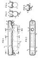
- the gas bag module 10 generally includes one tubular pressurized gas source 12 having at one axial end two outflow openings 14 and 16 is provided in the Shell surface of the compressed gas source 12 are arranged.
- the Pressurized gas source 12 is on an elongated mounting strip 18 attached to an axial end with a Flow opening 20 is provided by a cylindrical Extension is surrounded.
- the fastening strip 18 has two clamp-like for fastening the compressed gas source 12 Clamping sections 22, 24, one of which, namely the clamping section 22, in the area of the flow opening 20 is arranged while the other clamping section 24th closer to the other axial end of the mounting strip 18 is arranged.
- the clamping section 22 is also in the Provide area of the clamping gap with a cover plate 26.
- the compressed gas source 12 is in the two clamp-like Clamping sections 22, 24 clamped that the outflow opening 14 lies opposite the flow opening 20, while the Outflow opening 16 is closed by the cover plate 26.
- To facilitate the assembly of the compressed gas source 12 is on the fastening strip 18 has a stop plate 28, an axial stop for the compressed gas source 12 forms.
- the fastening strip 18 together with the this attached compressed gas source 12 forms a first pre-assembled assembly.
- a second is pre-assembled Assembly connected, which consists of an airbag 30, an in Elongated fastening frames arranged inside the gas bag 32 and an airbag cover 34.
- the fastening frames arranged in the interior of the gas bag 30 points to the cylindrical extension on the fastening strip complementary opening and is with bolt 36 provided that fixed to the mounting frame 32 and pass through the openings in the gas bag 30.
- the Airbag 30 is folded on the mounting frame 32, so that the width of the second assembly is essentially corresponds to the width of the first assembly.
- the gas bag cover 34 is attached, which is provided with fixing openings, the can also be crossed by the bolts 36. So are the gas bag 30, the mounting frame 32 and the gas bag cover 34 relative to each other by the bolts 36 as the second pre-assembled module fixed.
- the two modules are connected to each other by the second assembly is placed on the first assembly is that the bolt 36 through associated openings 38 of the Fastening strip 18 are inserted.
- the intervention of the cylindrical extension of the fastening strip into the complementary opening of the mounting frame supports the fixation of the two modules relatively to each other.
- suitable nuts 40 are placed on the bolts 36 screwed on to the first assembly firmly with the second to connect and by a clamping action between the Mounting frame 32 and the mounting strip 18 the Airbag cover 34 and airbag 30 (and possibly the mounting bracket).
- the mode of operation of the gas bag module according to the invention is the following:
- the compressed gas source is activated by a (Not shown) trigger sensor flows in the Compressed gas source 12 contains compressed gas only from the outflow opening 14 because the outflow opening 16 through the cover plate 26 is closed.
- the gas bag 30 is inflated and unfolded, the at the beginning of the unfolding process Airbag cover 34 is torn open.
- the configuration according to the invention results in the The following advantages:
- the gas bag module according to the invention is particularly compact because the width of the module the diameter the compressed gas source 12 plus twice the wall thickness of the Essentially does not exceed clamping sections.
- the Airbag module can easily be connected to different gas sources Performance can be adjusted, since compressed gas sources are approximately any length can be used without it the mounting strip 18 must be modified.
- the gas bag module can consist of two pre-assembled modules, which gives a special flexibility in assembly results. Due to the easily attachable to the bolt
- the airbag module according to the invention can be mounted at an angle particularly easy to the respective installation conditions in be adapted to the desired vehicle. By diminishing the cost of materials for the fastening strip 18th to the minimum necessary in terms of design, i.e.
Landscapes
- Engineering & Computer Science (AREA)
- Mechanical Engineering (AREA)
- Physics & Mathematics (AREA)
- Fluid Mechanics (AREA)
- Air Bags (AREA)
Claims (6)
- Module de coussin à gaz (10) pour un véhicule, comprenantune source de gaz comprimé (12) de forme générale tubulaire comportant, à une extrémité axiale, plusieurs orifices de sortie (14, 16) pour le gaz comprimé, ménagés dans sa surface enveloppe,une bande de fixation allongée (18) pourvue d'un orifice de passage d'écoulement (20) à une extrémité axiale et deux portions de serrage (22, 24) dont l'une est agencée dans la zone de l'orifice de passage d'écoulement (20) et dans lesquelles la source de gaz comprimé (12) est immobilisée par serrage de telle sorte qu'un orifice de sortie (14) est tourné vers l'orifice de passage d'écoulement (20),un coussin à gaz replié (30) qui est en communication fluidique avec la source de gaz comprimé (12) par l'intermédiaire de l'orifice de passage d'écoulement (20) et qui peut être déployé par le gaz comprimé, etun cadre de fixation allongé (32) qui est agencé à l'intérieur du coussin à gaz (30) et est relié à la bande de fixation (18), caractérisé en ce que les deux portions de serrage (22, 24) sont réalisées en forme de colliers et tous les autres orifices de sortie sont fermés par la portion de serrage (22) en forme de collier.
- Module de coussin à gaz selon la revendication 1, caractérisé en ce que le cadre de fixation (32) et le coussin à gaz (30) plié forment un ensemble préassemblé.
- Module de coussin à gaz selon l'une des revendications 1 et 2, caractérisé en ce que la source de gaz comprimé (12) et la bande de fixation (18) forment un ensemble préassemblé.
- Module de coussin à gaz selon l'une des revendications précédentes, caractérisé en ce que le cadre de fixation (32) est relié à la bande de fixation (18) par des goujons (36) qui sont immobilisés contre le cadre de fixation (32) et traversent des orifices de maintien du coussin à gaz (30), et en ce que le coussin à gaz (30) est immobilisé entre la bande de fixation (18) et le cadre de fixation (32).
- Module de coussin à gaz selon la revendication 4, caractérisé par un couvercle de coussin à gaz (34) qui est pourvu d'orifices de fixation qui sont traversés par les goujons (36).
- Module de coussin à gaz selon l'une des revendication 4 et 4, caractérisé en ce que sur les goujons (36) sont disposées des équerres de montage permettant de fixer le module (10) au véhicule.
Applications Claiming Priority (2)
| Application Number | Priority Date | Filing Date | Title |
|---|---|---|---|
| DE29606724U DE29606724U1 (de) | 1996-04-15 | 1996-04-15 | Gassack-Modul für ein Fahrzeug |
| DE29606724U | 1996-04-15 |
Publications (3)
| Publication Number | Publication Date |
|---|---|
| EP0802088A2 EP0802088A2 (fr) | 1997-10-22 |
| EP0802088A3 EP0802088A3 (fr) | 1999-01-07 |
| EP0802088B1 true EP0802088B1 (fr) | 2001-12-12 |
Family
ID=8022528
Family Applications (1)
| Application Number | Title | Priority Date | Filing Date |
|---|---|---|---|
| EP97104056A Expired - Lifetime EP0802088B1 (fr) | 1996-04-15 | 1997-03-11 | Module de coussin gonflable pour un véhicule |
Country Status (8)
| Country | Link |
|---|---|
| US (1) | US5752712A (fr) |
| EP (1) | EP0802088B1 (fr) |
| JP (1) | JP2883865B2 (fr) |
| KR (1) | KR100256163B1 (fr) |
| CN (1) | CN1168329A (fr) |
| DE (2) | DE29606724U1 (fr) |
| ES (1) | ES2109210T3 (fr) |
| TW (1) | TW333505B (fr) |
Families Citing this family (18)
| Publication number | Priority date | Publication date | Assignee | Title |
|---|---|---|---|---|
| DE19707997C2 (de) * | 1997-02-27 | 2000-10-26 | Hs Tech & Design | Beifahrerairbagvorrichtung |
| DE29606709U1 (de) * | 1996-04-12 | 1996-08-08 | Trw Repa Gmbh | Gassack |
| DE29614832U1 (de) * | 1996-08-26 | 1997-01-02 | Trw Occupant Restraint Systems Gmbh, 73551 Alfdorf | Befestigungsmittel bei einem Fahrzeuginsassen-Rückhaltesystem |
| DE19704684C2 (de) * | 1997-02-07 | 2000-08-10 | Johnson Contr Interiors Gmbh | Beifahrerairbagvorrichtung |
| DE29922941U1 (de) | 1999-12-23 | 2000-02-24 | Petri Ag, 63743 Aschaffenburg | Airbagmodul |
| DE10216217A1 (de) | 2002-04-05 | 2003-10-23 | Takata Petri Ag | Airbageinheit |
| DE10221101B4 (de) * | 2002-05-03 | 2005-04-28 | Takata Petri Ag | Airbagmodul für ein Kraftfahrzeug |
| DE10249375A1 (de) * | 2002-10-23 | 2004-05-19 | Trw Occupant Restraint Systems Gmbh & Co. Kg | Gassackmodul mit Gaslanze |
| DE10343012B4 (de) * | 2003-09-17 | 2006-03-16 | Autoliv Development Ab | Airbagmodul mit einem außenseitig des Modulgehäuses gehalterten Gasgenerator |
| DE10354560B4 (de) * | 2003-11-21 | 2007-08-02 | Trw Occupant Restraint Systems Gmbh & Co. Kg | Gassackmodul |
| DE10360468A1 (de) * | 2003-12-22 | 2005-08-04 | Trw Occupant Restraint Systems Gmbh & Co. Kg | Gassackmodul |
| JP2006248332A (ja) * | 2005-03-09 | 2006-09-21 | Takata Corp | 歩行者等保護用エアバッグ及び歩行者等保護用エアバッグ装置 |
| JP2007106215A (ja) * | 2005-10-12 | 2007-04-26 | Takata Corp | 乗員拘束装置 |
| DE202005016887U1 (de) * | 2005-10-20 | 2006-01-19 | Takata-Petri Ag | Airbagmodul, insbesondere für einen Knieairbag |
| US20080088119A1 (en) * | 2006-10-13 | 2008-04-17 | Yoshiki Murakami | Passenger constraining apparatus |
| CN102525036A (zh) * | 2010-12-23 | 2012-07-04 | 郑清辉 | 气压定型装置 |
| US11214219B2 (en) * | 2019-03-27 | 2022-01-04 | Toyoda Gosei Co., Ltd. | Airbag device |
| US11708043B2 (en) * | 2021-04-20 | 2023-07-25 | Autoliv Asp, Inc. | Inflator bracket |
Family Cites Families (6)
| Publication number | Priority date | Publication date | Assignee | Title |
|---|---|---|---|---|
| JP3004457B2 (ja) * | 1992-04-09 | 2000-01-31 | マツダ株式会社 | 自動車のエアバッグ取付構造及びその取付方法 |
| US5484163A (en) * | 1994-02-17 | 1996-01-16 | Trw Vehicle Safety Systems Inc. | Vehicle occupant restraint apparatus |
| DE4415374A1 (de) * | 1994-05-02 | 1995-11-09 | Trw Repa Gmbh | Gassack-Modul |
| US5639111A (en) * | 1995-03-29 | 1997-06-17 | General Motors Corporation | Air bag module |
| US5611563A (en) * | 1996-01-05 | 1997-03-18 | Morton International, Inc. | Airbag inflator attachment with snap-in sleeve |
| US5690354A (en) * | 1996-03-19 | 1997-11-25 | General Motors Corporation | Air bag module |
-
1996
- 1996-04-15 DE DE29606724U patent/DE29606724U1/de not_active Expired - Lifetime
-
1997
- 1997-03-11 ES ES97104056T patent/ES2109210T3/es not_active Expired - Lifetime
- 1997-03-11 DE DE59705725T patent/DE59705725D1/de not_active Expired - Fee Related
- 1997-03-11 TW TW086103073A patent/TW333505B/zh active
- 1997-03-11 EP EP97104056A patent/EP0802088B1/fr not_active Expired - Lifetime
- 1997-03-25 US US08/824,227 patent/US5752712A/en not_active Expired - Fee Related
- 1997-04-03 KR KR1019970012272A patent/KR100256163B1/ko not_active Expired - Fee Related
- 1997-04-14 JP JP9096100A patent/JP2883865B2/ja not_active Expired - Fee Related
- 1997-04-14 CN CN97110522A patent/CN1168329A/zh active Pending
Also Published As
| Publication number | Publication date |
|---|---|
| DE59705725D1 (de) | 2002-01-24 |
| US5752712A (en) | 1998-05-19 |
| JP2883865B2 (ja) | 1999-04-19 |
| ES2109210T1 (es) | 1998-01-16 |
| TW333505B (en) | 1998-06-11 |
| KR100256163B1 (ko) | 2000-05-15 |
| EP0802088A3 (fr) | 1999-01-07 |
| ES2109210T3 (es) | 2002-07-16 |
| CN1168329A (zh) | 1997-12-24 |
| JPH1035390A (ja) | 1998-02-10 |
| DE29606724U1 (de) | 1996-11-14 |
| KR970069651A (ko) | 1997-11-07 |
| EP0802088A2 (fr) | 1997-10-22 |
Similar Documents
| Publication | Publication Date | Title |
|---|---|---|
| EP0802088B1 (fr) | Module de coussin gonflable pour un véhicule | |
| EP1048531B1 (fr) | Dispositif de protection contre le choc latéral pour les occupants d'un véhicule | |
| EP0942851B1 (fr) | Dispositif de protection gonflable pour occupants d'un vehicule, destine a proteger en cas de choc lateral dans la zone de la tete ou du thorax | |
| DE69708536T2 (de) | Seitenaufprall-Luftsackmodul mit extrudiertem Deckel | |
| DE29706246U1 (de) | Gassack-Modul für ein Fahrzeuginsassen-Rückhaltesystem | |
| DE4310173C2 (de) | Airbagmodul | |
| DE19720588A1 (de) | Aufprallschutzeinrichtung für einen Insassen eins Fahrzeuges | |
| DE19752989B4 (de) | Seitenairbag-Vorrichtung | |
| EP1463652B1 (fr) | Repartiteur de flux gazeux pour module d'airbag lateral | |
| EP0761506B1 (fr) | Module pour sac gonflable de retenue | |
| DE29607362U1 (de) | Sicherheitsgurtsystem | |
| EP0857626A2 (fr) | Ensemble composé d'un générateur de gaz et d'une canalisation pour un système de retenue d'un occupant de véhicule | |
| DE19703767A1 (de) | Gehäuse für den Gassack in einem Kraftfahrzeug | |
| DE19610529A1 (de) | Anordnung eines Beifahrer-Airbags | |
| DE19824735B4 (de) | Airbagmodul für ein Fahrzeug | |
| DE19613095A1 (de) | Airbagvorrichtung | |
| EP1147949B1 (fr) | Module de sac de sécurité gonflable | |
| DE19710063B4 (de) | Airbag mit Gaserzeuger | |
| DE29812800U1 (de) | Gassackmodul für ein Fahrzeuginsassen-Rückhaltesystem | |
| EP0794091B1 (fr) | Module pour sac gonflable de retenue | |
| EP1022196B1 (fr) | Module pour sac gonflable de retenue | |
| DE29613269U1 (de) | Gassack-Modul für ein Fahrzeuginsassen-Rückhaltesystem | |
| EP1603776B1 (fr) | Dispositif de protection de passager | |
| EP1122133B1 (fr) | Dispositif protège-genoux actif à coussin gonflable, panneau de répartition de la force et attaches déchirables | |
| EP0849126A1 (fr) | Dispositif de retenue pour coussin de sécurité pour véhicule |
Legal Events
| Date | Code | Title | Description |
|---|---|---|---|
| PUAI | Public reference made under article 153(3) epc to a published international application that has entered the european phase |
Free format text: ORIGINAL CODE: 0009012 |
|
| AK | Designated contracting states |
Kind code of ref document: A2 Designated state(s): DE ES FR GB IT SE |
|
| ITCL | It: translation for ep claims filed |
Representative=s name: RACHELI & C. S.R.L. |
|
| GBC | Gb: translation of claims filed (gb section 78(7)/1977) | ||
| EL | Fr: translation of claims filed | ||
| REG | Reference to a national code |
Ref country code: ES Ref legal event code: BA2A Ref document number: 2109210 Country of ref document: ES Kind code of ref document: T1 |
|
| RAP1 | Party data changed (applicant data changed or rights of an application transferred) |
Owner name: TRW OCCUPANT RESTRAINT SYSTEMS GMBH & CO. KG |
|
| PUAL | Search report despatched |
Free format text: ORIGINAL CODE: 0009013 |
|
| AK | Designated contracting states |
Kind code of ref document: A3 Designated state(s): DE ES FR GB IT SE |
|
| 17P | Request for examination filed |
Effective date: 19990420 |
|
| GRAG | Despatch of communication of intention to grant |
Free format text: ORIGINAL CODE: EPIDOS AGRA |
|
| GRAG | Despatch of communication of intention to grant |
Free format text: ORIGINAL CODE: EPIDOS AGRA |
|
| GRAH | Despatch of communication of intention to grant a patent |
Free format text: ORIGINAL CODE: EPIDOS IGRA |
|
| 17Q | First examination report despatched |
Effective date: 20010530 |
|
| GRAH | Despatch of communication of intention to grant a patent |
Free format text: ORIGINAL CODE: EPIDOS IGRA |
|
| GRAA | (expected) grant |
Free format text: ORIGINAL CODE: 0009210 |
|
| AK | Designated contracting states |
Kind code of ref document: B1 Designated state(s): DE ES FR GB IT SE |
|
| PG25 | Lapsed in a contracting state [announced via postgrant information from national office to epo] |
Ref country code: GB Free format text: LAPSE BECAUSE OF FAILURE TO SUBMIT A TRANSLATION OF THE DESCRIPTION OR TO PAY THE FEE WITHIN THE PRESCRIBED TIME-LIMIT Effective date: 20011212 |
|
| REG | Reference to a national code |
Ref country code: GB Ref legal event code: IF02 |
|
| REF | Corresponds to: |
Ref document number: 59705725 Country of ref document: DE Date of ref document: 20020124 |
|
| PG25 | Lapsed in a contracting state [announced via postgrant information from national office to epo] |
Ref country code: SE Free format text: LAPSE BECAUSE OF FAILURE TO SUBMIT A TRANSLATION OF THE DESCRIPTION OR TO PAY THE FEE WITHIN THE PRESCRIBED TIME-LIMIT Effective date: 20020312 |
|
| ET | Fr: translation filed | ||
| GBV | Gb: ep patent (uk) treated as always having been void in accordance with gb section 77(7)/1977 [no translation filed] |
Effective date: 20011212 |
|
| REG | Reference to a national code |
Ref country code: ES Ref legal event code: FG2A Ref document number: 2109210 Country of ref document: ES Kind code of ref document: T3 |
|
| PLBE | No opposition filed within time limit |
Free format text: ORIGINAL CODE: 0009261 |
|
| STAA | Information on the status of an ep patent application or granted ep patent |
Free format text: STATUS: NO OPPOSITION FILED WITHIN TIME LIMIT |
|
| 26N | No opposition filed | ||
| PGFP | Annual fee paid to national office [announced via postgrant information from national office to epo] |
Ref country code: FR Payment date: 20050302 Year of fee payment: 9 |
|
| PGFP | Annual fee paid to national office [announced via postgrant information from national office to epo] |
Ref country code: ES Payment date: 20050314 Year of fee payment: 9 |
|
| PG25 | Lapsed in a contracting state [announced via postgrant information from national office to epo] |
Ref country code: ES Free format text: LAPSE BECAUSE OF NON-PAYMENT OF DUE FEES Effective date: 20060313 |
|
| PGFP | Annual fee paid to national office [announced via postgrant information from national office to epo] |
Ref country code: DE Payment date: 20060330 Year of fee payment: 10 |
|
| PGFP | Annual fee paid to national office [announced via postgrant information from national office to epo] |
Ref country code: IT Payment date: 20060331 Year of fee payment: 10 |
|
| REG | Reference to a national code |
Ref country code: FR Ref legal event code: ST Effective date: 20061130 |
|
| REG | Reference to a national code |
Ref country code: ES Ref legal event code: FD2A Effective date: 20060313 |
|
| PG25 | Lapsed in a contracting state [announced via postgrant information from national office to epo] |
Ref country code: FR Free format text: LAPSE BECAUSE OF NON-PAYMENT OF DUE FEES Effective date: 20060331 Ref country code: DE Free format text: LAPSE BECAUSE OF NON-PAYMENT OF DUE FEES Effective date: 20071002 |
|
| PG25 | Lapsed in a contracting state [announced via postgrant information from national office to epo] |
Ref country code: IT Free format text: LAPSE BECAUSE OF NON-PAYMENT OF DUE FEES Effective date: 20070311 |