EP0802094B1 - Réglage en hauteur d'un renvoi de ceinture de sécurité - Google Patents
Réglage en hauteur d'un renvoi de ceinture de sécurité Download PDFInfo
- Publication number
- EP0802094B1 EP0802094B1 EP19970106590 EP97106590A EP0802094B1 EP 0802094 B1 EP0802094 B1 EP 0802094B1 EP 19970106590 EP19970106590 EP 19970106590 EP 97106590 A EP97106590 A EP 97106590A EP 0802094 B1 EP0802094 B1 EP 0802094B1
- Authority
- EP
- European Patent Office
- Prior art keywords
- catch
- rail
- deflection
- bearing
- slider
- Prior art date
- Legal status (The legal status is an assumption and is not a legal conclusion. Google has not performed a legal analysis and makes no representation as to the accuracy of the status listed.)
- Expired - Lifetime
Links
- 238000006073 displacement reaction Methods 0.000 claims description 11
- 230000000875 corresponding effect Effects 0.000 description 7
- 238000003892 spreading Methods 0.000 description 6
- 238000004519 manufacturing process Methods 0.000 description 5
- 238000003860 storage Methods 0.000 description 3
- 230000000903 blocking effect Effects 0.000 description 2
- 238000010276 construction Methods 0.000 description 2
- 230000002950 deficient Effects 0.000 description 2
- 230000000694 effects Effects 0.000 description 2
- 238000009434 installation Methods 0.000 description 2
- 230000008719 thickening Effects 0.000 description 2
- 238000013459 approach Methods 0.000 description 1
- 230000002596 correlated effect Effects 0.000 description 1
- 230000003247 decreasing effect Effects 0.000 description 1
- 238000013461 design Methods 0.000 description 1
- 230000009977 dual effect Effects 0.000 description 1
- 239000000463 material Substances 0.000 description 1
- 239000002184 metal Substances 0.000 description 1
- 238000000034 method Methods 0.000 description 1
- 238000012549 training Methods 0.000 description 1
- 238000013519 translation Methods 0.000 description 1
Images


Classifications
-
- B—PERFORMING OPERATIONS; TRANSPORTING
- B60—VEHICLES IN GENERAL
- B60R—VEHICLES, VEHICLE FITTINGS, OR VEHICLE PARTS, NOT OTHERWISE PROVIDED FOR
- B60R22/00—Safety belts or body harnesses in vehicles
- B60R22/18—Anchoring devices
- B60R22/20—Anchoring devices adjustable in position, e.g. in height
- B60R22/201—Anchoring devices adjustable in position, e.g. in height with the belt anchor connected to a slider movable in a vehicle-mounted track
- B60R22/205—Anchoring devices adjustable in position, e.g. in height with the belt anchor connected to a slider movable in a vehicle-mounted track the slider comprising emergency actuated locking means
Definitions
- the present invention relates to a device for automatically height-adjustable storage of the upper fastening or deflection fitting for a seat belt in a vehicle with a substantially vertically arranged Rail, which has side catches with a sliding piece that can be moved along the rail, in which a pawl with a laterally protruding locking lug between an engagement position and an engagement position about an axis perpendicular to the longitudinal direction of the rail is pivotally mounted, with a on the jack in the attacking a displacement direction, depending on controlled the seat position of the assigned vehicle seat Adjustment element and with a movable with the slider Bearing for the deflection fitting, which is so on the pawl attacks that the pawl when the bearing is loaded is pivoted into its locked position by the belt.
- Such a device is for example from the DE 38 02 323 C2 known.
- this known device is the pawl by a predetermined by the slider Pivot point pivotally mounted in the slider. On one side of the pivot point grips the handle Adjustment element in one pivot direction while the pawl on the other side of the pivot point a return element acting in the reverse direction of pivoting supported. This causes a shift the slider along the rail without loading the bearing for the deflection fitting ensures that the pawl in remains in its disengaged position.
- the bearing for the deflection fitting is known in this Device firmly connected to the slider. At a Load on the bearing, especially in the event of an accident occurs, therefore the slider with pivot point in the Rail moves down while the latch is on one Side of the pivot point from that through the sitting position fixed adjustment element is held. Thereby pivots the latch and snaps into one of the side Locking recordings of the rail so that the slider with the Bearing for the deflection fitting against further displacement is blocked along the rail.
- the present invention is therefore based on the object to develop a device of the type mentioned so that these disadvantages do not occur.
- the facility despite ensuring a safe shift of the slider in both directions, simplified in structure to reduce manufacturing costs and the Increase functional reliability.
- This object is achieved in a device of the type mentioned in the present invention in that a attacking the handle in the other direction of displacement Restoring element is provided, and that the adjusting element and the return element on the pawl on two on the same Attack the points on the side of the swivel axis.
- the Reset element provided according to the invention thus has a Dual function.
- the reset element transfers the slider counteracting the adjusting element
- the restoring element prevents displacement and secondly a latching of the pawl during the adjustment of the Establishment, i.e. with the warehouse unloaded. On snapping Preventing separate reset element can therefore be omitted. This gives you an improved in function and nevertheless simple in construction, which was reduced by Manufacturing costs and increased durability, because there are fewer parts that are subject to wear subject to or fail.
- the bearing for the Deflection fitting arranged on the pawl, the arrangement offset horizontally to the point of attack of the adjusting element is provided.
- This staggered arrangement causes when the bearing for the deflection fitting is loaded Pawl in its locked position relative to the slider is pivoted, because the one transferred from the belt to the bearing Pulling movement downwards works through the sitting position fixed adjustment element counter. The one picked up by the camp This transmits power directly to the jack, so that the slider is not designed for this high force have to be. There is not even one on the slide Pivot bearing required, although after one preferred embodiment of the invention is provided.
- this is on the pawl arranged bearing for the deflection fitting on the Axis of rotation of the pawl provided in the slider.
- One off the belt force transmitted to the bearing for the deflection fitting therefore attacks vertically downwards on the pivot axis and tries to pull the latch down along the rail move.
- Due to the bearing of the deflection fitting staggered on the pawl adjusting element results resulting torque, which leads to a Swiveling the pawl and snapping it into place lateral snap-in recordings of the rail leads.
- the Click a bushing through which a longitudinally stepped Pin with its narrower than a bearing for the deflection fitting trained section is passed, wherein the wider section of the pin than the pivot pin is formed, which is in a corresponding circular Recess of the slider is rotatably mounted.
- this configuration becomes a simple pivot bearing the pawl in the slider causes.
- the tiered design of the pin has the advantage that the Pin when the deflection fitting is loaded by the Belt cannot be pulled out of the pawl. Too too during normal operation of the device a secure fit of the To ensure the bearing for the deflection fitting in the pawl, is the stepped pin with its narrower Section preferably with a press fit into the pawl used.
- Jack stored in a two-part housing the The lower part of the housing serves as a slider and the upper part of the housing together with the latch opposite the lower part of the housing is pivotable in the rail plane, which Adjustment element and the reset element on the upper part of the housing attack.
- This configuration enables simple Attachment of the adjusting element and the restoring element the upper housing part, which is made in particular of plastic can be made, and at the same time training the Jack made of a particularly stable material, in particular Metal.
- the rail is preferably a rope, in particular a Bowden cable.
- the Bowden cable is preferably via a deflection device guided and grips the handle from above or on the upper part of the housing. The other end of the Bowden cable is moved when the vehicle seat is moved, that the Bowden cable in the foremost seating position on is extended as far as possible, so that the deflection fitting is in its lowest position. Conversely, the Bowden cable the deflection fitting into its uppermost position, if the vehicle seat is in its rearmost position. At the lower end of the jack or upper part of the housing grips the restoring element accordingly in this embodiment which therefore deflects the fitting into its lowest Prestressed position. When extending the Bowden cable thereby ensuring that the deflection fitting in the desired Position is shifted down.
- the Coil spring preferably in one that can be anchored in the rail Spring sleeve is mounted, which is a central implementation for a fastening bolt.
- the spring sleeve serves thus in addition to the storage of the coil spring Attaching the rail to the vehicle.
- the Spring sleeve also with a side mount for the end of the jacket of the Bowden cable, so that the spring sleeve performs another function.
- Pawl provided an expansion spring element, which by the clamping force acting between the adjusting element and the restoring element is held in an open position, the Spreading spring element between pawl and slide or is arranged between the pawl and rail that the pawl in the event of loss of the clamping force from the spreading spring element in Direction is loaded onto its latching position.
- the Spreading spring element is advantageously ensured that the pawl even if the adjusting element is defective or the reset element or an associated Partly, for example if the Bowden cable, clicks into place and the slide with the bearing for the deflection fitting against vertical displacement is blocked. If the adjustment element is defective the clamping force away, so that the spreading spring element spreads and the pawl is pivoted into its locked position.
- the spreading spring element is preferred as a bracket with two resilient legs formed in spread Condition with one leg on the handle and with supports his other leg on the slider, the Span of the bracket depending on the tension is changeable. If there is tension, the swiveled both legs of the bracket so far that the bracket does not exert any pivoting force on the latch. falls the tension away, the bracket spreads and loads the Pawl in the locking direction.
- the Click a contact edge for at least one part at a time of the two legs of the bracket and the bracket is through the tension is held against the contact edge so that the two legs are pivoted so far that the Jack is relieved of the bracket.
- the contact edge can preferably through a recess in the area of the Point of attack of the adjusting element be formed, and that Adjustment element can preferably at the junction of the attack both legs of the bracket and this against the Pull the contact edge.
- This configuration makes the spreading spring element cleverly integrated into the jack and is by the adjusting element, such as the Bowden cable, held in an open position, as long as none Breakage occurs. If the Bowden cable breaks or if unintentional posting of the same, however, falls Traction of the Bowden cable on the bracket away, so that this spreads and through its two legs the latch in Snap direction loaded.
- the height of the deflection fitting is possible after one Another embodiment of the invention provided that the Distance of the deflection device for the Bowden cable from the upper one End of the rail is manually adjustable. With everyone about the Seat position adjusted length of the Bowden cable can thus the predetermined height of the deflection fitting certain area can also be changed. So that can take into account the fact that those of a Person's chosen seating position is not always complete their height or shoulder height correlated.
- the deflection device For the additional manual adjustment, the deflection device according to a further embodiment of the invention one rotatable about a substantially horizontal axis stored lever element, which is a deflecting element for carries the Bowden cable and an actuator, which Deflection element closer to the axis of rotation of the lever element is arranged as the actuating element.
- a substantially horizontal axis stored lever element which is a deflecting element for carries the Bowden cable and an actuator, which Deflection element closer to the axis of rotation of the lever element is arranged as the actuating element.
- the Bowden cable is deflected the invention preferably a deflection roller is provided.
- the one that occurs when the Bowden cable is operated This reduces friction, which on the one hand improves functional reliability the facility increased and on the other hand a additional manual height adjustment made easier.
- the intended snap-in receptacle is the device according to the invention for double-sided use in a motor vehicle suitable. All parts of the device according to the invention Exception of the upper part of the housing can then be used for both can also be used for right-hand installation.
- the rail is preferably with slots for hanging in an existing holder on the vehicle Mistake.
- the assembly of the device according to the invention will thereby greatly facilitated.
- the rail is in the for example on the B-pillar of the vehicle Mounted from below, and then only has to still by means of the only one guided through the spring sleeve Fastening bolt to be attached to the B-pillar.
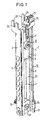
- the height adjustment device according to the invention shown in Fig. 1 for the deflection fitting of a seat belt includes a vertical, for example on the B-pillar Motor vehicle to be mounted rail 1, which two in Cross-section C-shaped side legs 2, the the rear of the rail with each other via a rear wall 3 are connected.
- a vertical for example on the B-pillar Motor vehicle to be mounted rail 1
- two in Cross-section C-shaped side legs 2 the the rear of the rail with each other via a rear wall 3 are connected.
- each Locking receptacles 4 provided, as shown, for example by expressing corresponding sections 5 of the lateral leg 2 can be generated.
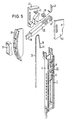
- the lower housing part 7 is slidably guided along the rail 1.
- the housing 6 takes a pawl 8, which together with the upper housing part 9 relative to the lower housing part 7 around a central one Axis I is rotatable.
- pawl 8 provided with recesses 26, in which corresponding, in Upper housing part 9 provided, not shown here Intervene projections.
- One of the two recesses 26 and the associated projection can be compared to the central one Axis I may be misaligned for incorrect assembly by turning pawl 8 and upper housing part by 180 ° to prevent each other.
- the pawl 8 has a laterally projecting nose 10 as well as a central bushing 11, in which a how out Fig. 3 can be seen, stepped pin 12 with its narrower section 13 is inserted with a press fit.
- the narrower section 13 is designed as a threaded bushing, which through a central passage 14 in the upper housing part 9 is performed and as a bearing for a corresponding Threaded bolt of a deflection fitting, not shown here serves.
- the wider section 15 of the tiered Pin 12 has a diameter that is related to the diameter adapted a recess 16 in the lower housing part 7 is so that the wider portion 15 of the stepped pin 12 with the recess 16 in the lower housing part as a pivot bearing for the pawl 8 and the upper housing part 9 cooperates.
- the upper housing part 9 has in its above the bushing 14 located section a receptacle 17 for the end 18 of a Bowden cable 19, which has a deflection device 20 led from above to the upper housing part 9 is.
- the end 18 of the Bowden cable 19 has a thickening 21 provided which has an associated edge in the receptacle 17 engages in the upper housing part 9. How to in particular 4 can be seen, the receptacle 17 for the Bowden cable 19 opposite the central axis I, around which the Upper housing part 9 is rotatable, horizontally offset arranged.
- the deflection device 20 equipped with a pulley 27, about which the Bowden cable 19 is guided. That way the friction when operating the Bowden cable 19 is reduced.
- this is End 28 of the jacket of the Bowden cable 19 in a side the spring bearing 25 provided receptacle 29 mounted.
- the spring bearing 25 has a central passage 30, through which a fastening bolt 31 with interposition a snap ring 32 can be passed through to this Assign the lower end of the rail 1 to the motor vehicle Fasten.
- the upper end of the rail 1 is perpendicular to two Rail-level approaches 33 provided in which in each case an upwardly open slot 34 is formed. With these slots 34, the rail 1 is in a corresponding intended receptacle on the motor vehicle can be used. For fastening the rail 1 in the motor vehicle is therefore only a single fastening bolt 31 is required.
- the Jacket end 28 outstanding length of the Bowden cable 19 accordingly chosen, this automatically depending from the position of the associated vehicle seat.
- the Connection to the vehicle seat is provided so that when the vehicle seat is in the foremost position greatest length of the Bowden cable 19 is present, so that the housing 6 with the bearing 12 for the deflection fitting due to the force the coil spring 23 in the lowest position in the rail 1 is moved while in the rearmost position of the vehicle seat the Bowden cable 19, the housing 6 with the on the jack 8 existing bearings 12 for the deflection fitting against Force of the coil spring 23 pulls into the uppermost position.
- Around different displacement of the vehicle seat and Compensating the deflection fitting can be a for the Bowden cable Translation device may be provided. When moving of the housing 6 acts without loading the bearing 12 the pawl 8, as stated, no resulting torque, so that the pawl 8 in its height adjustment disengaged position remains.
- the device according to the invention thus makes it simple built, automatically height-adjustable device for Storage of the upper fastening or deflection fitting for a seat belt, which in the event of an accident quick and safe blocking of the deflection fitting guaranteed. Few components are required, which are also up to on the upper housing part 9 for both left-hand and also for right-hand installation in a motor vehicle can be used, both the manufacturing cost decreased as well as warehousing and assembly simplified.
- the height of the deflection fitting can Deflection device 20 at the top of the rail 1 so be arranged that the distance of the guide roller 27 from upper end of the rail 1 is manually adjustable.
- the path of the Bowden cable 19 is increased extended to receive 17 in the upper housing part 9, so that with the seating position unchanged, the housing 6 with the bearing 12 is displaced upwards for the deflection fitting.
- the housing 6 by reducing the distance to be moved down.
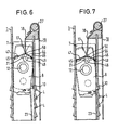
- FIG. 5 shows such a deflection device 20 additionally Manually adjustable deflection element for the Bowden cable 19.
- a deflection element is one in one Lever element 35 provided deflection roller 36 is provided which the Bowden cable 19 rotates.
- the lever element 35 is on its one, tapered end 38 by a Detent guide 39 guided and 38 at this end attachable actuator 37.
- the other end 40 of the Lever element 35 is rotatably mounted on a pin 41, which is housed in a housing 42.
- Housing 42 has a spring 43 anchored at one end, the other end engages the lever element 35 and this is loaded into its lower swivel position.
- a bracket 44 with two resilient legs 45, 46 provided that one leg 45 on the Jack 8 and with its other leg 46 on the Slider 7 supports.
- the bracket 44 sits in one a contact edge 47 for the legs 45, 46 of the bracket 44 forming recess 48 of the pawl 8, which is dimensioned so that the bracket 44 with its two legs 45, 46 between an open position in which the legs 45, 46 abut the contact edge 47, and a spread Position in which the two legs 45, 46 continue are pivoted apart, is movable.
- the recess 48 opens on one side into a side opening 49 in the Pawl 8, through which one leg 46 of the bracket 44 in Pick out spread position and on the Can support slide 7.
- the recess 48 for the bracket 44 is in the area of Receptacle 17 arranged for the end 18 of the Bowden cable 19, that the thickening 21 of the Bowden cable 19 when inserted Bowden cable comes to rest in the recess 48.
- the Bowden cable 19 is not only in the recording 17 but at the same time suspended in the appropriately designed bracket 44, so that the Bowden cable 19 in the tensioned state Bracket 44 against the contact edge formed by the recess 48 47 pulls.
- the in. Acts as a counterforce opposite direction attacking on the pawl 8 Coil spring 23.
- This leg 46 thereby supports itself on the opposite inner wall of the Slider 7 from so that over the other leg 45 of the Bracket 44 is applied to the pawl 8 a pivoting force.
- This pivoting force acts in the latching direction of the pawl 8, so that the pawl 8 engages in one of the locking receptacles 4 and the slider with the bearing 12 for the deflection fitting against another shift is blocked.
Landscapes
- Engineering & Computer Science (AREA)
- Mechanical Engineering (AREA)
- Seats For Vehicles (AREA)
- Automotive Seat Belt Assembly (AREA)
Claims (19)
- Dispositif pour le montage réglable automatiquement en hauteur de l'armature d'ancrage ou de renvoi supérieure pour une ceinture de sécurité dans un véhicule, avec un rail (1) disposé sensiblement verticalement qui présente latéralement des encoches de verrouillage (4), avec une pièce coulissante (7) guidée de manière mobile le long du rail (1), dans laquelle une clenche (8), avec un nez de verrouillage (10) dépassant latéralement, est disposée de manière à pivoter entre une position de verrouillage et une position de déverrouillage autour d'un axe (I) perpendiculaire à la direction longitudinale du rail, avec un élément de réglage (19) agissant sur la clenche (8) dans l'un des sens de déplacement, commandé en fonction de la position du siège du véhicule auquel il est affecté, et avec un palier (12) pour l'armature de renvoi, mobile avec la pièce coulissante, qui agit sur la clenche (8) de sorte que la clenche (8), sous l'effet d'un effort exercé sur le palier (12), est pivotée par la ceinture dans sa position de verrouillage,
caractérisé en ce que
un élément de rappel (23) agissant sur la clenche (8) dans l'autre sens de déplacement est prévu, et en ce que l'élément de réglage (19) et l'élément de rappel (23) agissent sur la clenche (8) en deux points (17, 24) disposés du même côté de l'axe de pivotement (I). - Dispositif selon la revendication 1,
caractérisé en ce que
le palier (12) pour l'armature de renvoi est disposé sur la clenche (8) vis-à-vis du point d'attaque (17) de l'élément de réglage (19), de manière décalée horizontalement. - Dispositif selon la revendication 2,
caractérisé en ce que
la pièce coulissante (7) présente un montage pivotant (16) de préférence central pour la clenche (8). - Dispositif selon la revendication 3,
caractérisé en ce que
le palier (12) pour l'armature de renvoi présent sur la clenche (8) est prévu sur l'axe de rotation (I) de la clenche (8) dans la pièce coulissante (7). - Dispositif selon la revendication 4,
caractérisé en ce que
la clenche (8) comporte un passage (11) par lequel passe la partie (13) plus étroite, configurée comme palier pour l'armature de renvoi, d'un axe (12) étagé sur sa longueur, et en ce que la partie plus large (15) de l'axe (12) est configurée comme axe de palier de pivotement monté pivotant dans un évidement (16) circulaire correspondant de la pièce coulissante (7). - Dispositif selon l'une des revendications précédentes,
caractérisé en ce que
la clenche (8) est disposée dans un boítier (6) en deux parties dont la partie inférieure de boítier (7) fait office de pièce coulissante et dont la partie supérieure de boítier (9), avec la clenche (8), est pivotante dans le plan du rail par rapport à la partie inférieure de boítier (7), l'élément de réglage (19) et l'élément de rappel (23) agissant sur la partie supérieure de boítier (9). - Dispositif selon l'une des revendications précédentes,
caractérisé en ce que
un câble, en particulier un câble Bowden (19) fait office d'élément de réglage. - Dispositif selon la revendication 7,
caractérisé en ce que
le câble (19) est guidé par un dispositif de renvoi (20) et agit par le haut sur la clenche (8) ou sur la partie supérieure du boítier (9). - Dispositif selon l'une des revendications précédentes,
caractérisé en ce que
un ressort spiral (23) monté dans un boítier de ressort (25) pouvant être ancré dans le rail (1) et présentant un passage central (30) pour un boulon de fixation (31), est prévu en tant qu'élément de rappel. - Dispositif selon la revendication 9,
caractérisé en ce que
un logement latéral (29) est prévu sur le boítier de ressort (25) pour l'extrémité (28) de la gaine du câble Bowden (19). - Dispositif selon l'une des revendications précédentes,
caractérisé en ce que
un élément ressort écarteur (44) est prévu sur la clenche (8), qui est maintenu en position comprimée par l'effort de tension agissant entre l'élément de réglage (19) et l'élément de rappel (23), et en ce que l'élément ressort écarteur (44) est disposé entre la clenche (8) et la pièce coulissante (7) ou entre la clenche (8) et le rail (1) de telle sorte que, lors de la disparition de l'effort de tension, l'élément ressort écarteur (44) agit sur la clenche (8) dans la direction de la position de verrouillage de celle-ci. - Dispositif selon la revendication 11,
caractérisé en ce que
l'élément ressort écarteur est configuré en forme d'arceau (44) avec deux branches élastiques (45, 46), qui, à l'état écarté, appuie par l'une de ses branches (45) sur la clenche (8) et par son autre branche (46) sur la partie coulissante (7), et dont l'ouverture est variable en fonction de l'effort de tension. - Dispositif selon la revendication 12,
caractérisé en ce que
la clenche (8) présente une face d'appui (47) au moins pour une partie de chacune des deux branches (45, 46) de l'arceau (44), et en ce que l'arceau (44) est maintenu par l'effort de tension contre la face d'appui (47) de telle sorte que les deux branches sont pivotées l'une et l'autre de façon à ce que la clenche (8) soit libérée de l'effort de pivotement de l'arceau (44). - Dispositif selon la revendication 13,
caractérisé en ce que
la face d'appui (47) est formée par un évidement (48) dans la zone du point d'attaque (17) de l'élément de réglage (19) sur la clenche (8), et en ce que l'élément de réglage (19) agit au point de liaison (50) des deux branches (45, 46) de l'arceau (44) et tire celui-ci contre la face d'appui (47). - Dispositif pour le montage réglable automatiquement en hauteur de l'armature d'ancrage ou de renvoi supérieure pour une ceinture de sécurité dans un véhicule, avec un rail (1) disposé sensiblement verticalement qui présente latéralement des encoches de verrouillage (4), avec une pièce coulissante (7) guidée de manière mobile le long du rail (1), dans laquelle une clenche (8), avec un nez de verrouillage (10) dépassant latéralement, est disposée de manière à pivoter entre une position de verrouillage et une position de déverrouillage autour d'un axe (I) perpendiculaire à la direction longitudinale du rail, avec un câble Bowden (19) agissant sur la clenche (8) depuis le haut dans le sens du déplacement et guidé par un dispositif de renvoi (20) disposé au-dessus du rail (1), selon l'une des revendications précédentes,
caractérisé en ce que
la distance du dispositif de renvoi (20) du câble Bowden (19) par rapport à l'extrémité supérieure du rail (1) est réglable manuellement. - Dispositif selon la revendication 15,
caractérisé en ce que
le dispositif de renvoi (20) présente un élément levier (35) monté pivotant autour d'un axe sensiblement horizontal (II) et portant un élément de renvoi (36) pour le câble Bowden (19) et un élément d'actionnement (37), et en ce que l'élément de renvoi (36) est disposé plus près de l'axe de rotation (II) de l'élément levier (35) que l'élément d'actionnement (37). - Dispositif selon la revendication 15 ou 16,
caractérisé en ce que
un galet de renvoi (27) monté tournant est prévu pour le renvoi du câble Bowden (19). - Dispositif selon l'une des revendications précédentes,
caractérisé en ce que
le rail (1) est muni, sur deux côtés se faisant face, d'encoches de verrouillage (4). - Dispositif selon l'une des revendications précédentes,
caractérisé en ce que
le rail (1) présente, à son extrémité supérieure, des rainures (33) pour l'accrochage dans un logement prévu dans le véhicule.
Applications Claiming Priority (4)
| Application Number | Priority Date | Filing Date | Title |
|---|---|---|---|
| DE19615652 | 1996-04-19 | ||
| DE19615652 | 1996-04-19 | ||
| DE19626799A DE19626799A1 (de) | 1996-04-19 | 1996-07-03 | Höhenverstellung für den Umlenkbeschlag eines Sicherheitsgurts |
| DE19626799 | 1996-07-03 |
Publications (3)
| Publication Number | Publication Date |
|---|---|
| EP0802094A2 EP0802094A2 (fr) | 1997-10-22 |
| EP0802094A3 EP0802094A3 (fr) | 2001-01-03 |
| EP0802094B1 true EP0802094B1 (fr) | 2004-02-11 |
Family
ID=26024934
Family Applications (1)
| Application Number | Title | Priority Date | Filing Date |
|---|---|---|---|
| EP19970106590 Expired - Lifetime EP0802094B1 (fr) | 1996-04-19 | 1997-04-21 | Réglage en hauteur d'un renvoi de ceinture de sécurité |
Country Status (1)
| Country | Link |
|---|---|
| EP (1) | EP0802094B1 (fr) |
Families Citing this family (3)
| Publication number | Priority date | Publication date | Assignee | Title |
|---|---|---|---|---|
| DE29808844U1 (de) * | 1998-05-15 | 1998-09-17 | TRW Occupant Restraint Systems GmbH & Co. KG, 73553 Alfdorf | Umlenkbeschlag mit automatischer Verstellvorrichtung |
| US11377066B1 (en) * | 2020-06-08 | 2022-07-05 | Apple Inc. | Safety systems for reclined seats |
| CN113109431B (zh) * | 2021-04-19 | 2024-05-03 | 中兴海陆工程有限公司 | 一种提高检查精准度的金属螺纹管涡流探伤仪辅助装置 |
Family Cites Families (4)
| Publication number | Priority date | Publication date | Assignee | Title |
|---|---|---|---|---|
| DE3713137A1 (de) * | 1987-04-16 | 1988-11-03 | Trw Repa Gmbh | Sicherheitsgurt-rueckhaltesystem fuer fahrzeuginsassen |
| DE3802323C2 (de) * | 1988-01-27 | 1994-09-08 | Autoflug Gmbh | Fernbetätigbare Höhenverstellvorrichtung |
| DE3844258A1 (de) * | 1988-12-29 | 1990-07-12 | Autoliv Kolb Gmbh & Co Kg | Hoehenverstellbarer umlenkbeschlag fuer sicherheitsgurte von kraftfahrzeugen |
| DE3938612A1 (de) * | 1989-11-21 | 1991-05-23 | Daimler Benz Ag | Vorrichtung zur hoehenverstellung des oberen verankerungs- bzw. umlenkpunktes eines sicherheitsgurtsystemes |
-
1997
- 1997-04-21 EP EP19970106590 patent/EP0802094B1/fr not_active Expired - Lifetime
Also Published As
| Publication number | Publication date |
|---|---|
| EP0802094A2 (fr) | 1997-10-22 |
| EP0802094A3 (fr) | 2001-01-03 |
Similar Documents
| Publication | Publication Date | Title |
|---|---|---|
| DE3724138C2 (de) | Gleitvorrichtung für einen Fahrzeugsitz | |
| EP1080985B1 (fr) | Accoudoir pour siège de véhicule | |
| DE68916526T3 (de) | Fahrzeug-Türschlosssystem. | |
| DE102014206537B4 (de) | Fahrzeugsitz, insbesondere kraftfahrzeugsitz | |
| EP1291236B1 (fr) | Dispositif de déverrouillage pour sièges de véhicules | |
| DE10048332A1 (de) | Vertikalpositionierungseinrichtung für einen Fahrzeugsitz | |
| EP1107878B1 (fr) | Dispositif de fixation pour siege enfant | |
| DE19654851C1 (de) | Seilfensterheber mit einer Führungsschiene | |
| EP1392545B1 (fr) | Siege de vehicule automobile | |
| DE10036968A1 (de) | Sitzlehnenverriegelungsvorrichtung | |
| EP3057823B1 (fr) | Siège de véhicule dans lequel est intégré un système d'accès facile | |
| DE102013210329B4 (de) | Griffverstelleranordnung | |
| DE4040514C2 (de) | Fahrzeugsitzanordnung | |
| DE2103820A1 (de) | Rolladen | |
| EP0802094B1 (fr) | Réglage en hauteur d'un renvoi de ceinture de sécurité | |
| EP0150065A2 (fr) | Dispositif d'ancrage ou de renvoi réglable en hauteur pour ceinture de sécurité de véhicule | |
| WO2003101776A1 (fr) | Dispositif d'actionnement manuel d'un dispositif de blocage pour systeme de reglage en longueur d'un siege d'automobile sur glissieres | |
| DE3642349A1 (de) | Fahrzeugsitz mit einer laengsfuehrung, mit einer hoehen- oder neigungsverstellung und mit einer gurtschlossbefestigung | |
| DE68905756T2 (de) | Handvorrichtung zur verstellung eines sicherheitsgurtels. | |
| EP0802095A2 (fr) | Système de ceinture de sécurité | |
| DE19940813A1 (de) | Längseinstellvorrichtung für einen Fahrzeugsitz | |
| DE10157516B4 (de) | Kraftfahrzeug-Sitz | |
| DE19981927C1 (de) | Seilzug-Fensterheber für Fahrzeuge | |
| DE19626799A1 (de) | Höhenverstellung für den Umlenkbeschlag eines Sicherheitsgurts | |
| DE1949085C3 (de) | Fahrzeugsitz, insbesondere Kraftfahrzeugsitz |
Legal Events
| Date | Code | Title | Description |
|---|---|---|---|
| PUAI | Public reference made under article 153(3) epc to a published international application that has entered the european phase |
Free format text: ORIGINAL CODE: 0009012 |
|
| AK | Designated contracting states |
Kind code of ref document: A2 Designated state(s): DE GB |
|
| PUAL | Search report despatched |
Free format text: ORIGINAL CODE: 0009013 |
|
| AK | Designated contracting states |
Kind code of ref document: A3 Designated state(s): DE GB |
|
| 17P | Request for examination filed |
Effective date: 20010627 |
|
| RAP1 | Party data changed (applicant data changed or rights of an application transferred) |
Owner name: TAKATA-PETRI (ULM) GMBH |
|
| 17Q | First examination report despatched |
Effective date: 20021227 |
|
| GRAP | Despatch of communication of intention to grant a patent |
Free format text: ORIGINAL CODE: EPIDOSNIGR1 |
|
| GRAS | Grant fee paid |
Free format text: ORIGINAL CODE: EPIDOSNIGR3 |
|
| GRAA | (expected) grant |
Free format text: ORIGINAL CODE: 0009210 |
|
| AK | Designated contracting states |
Kind code of ref document: B1 Designated state(s): DE GB |
|
| REG | Reference to a national code |
Ref country code: GB Ref legal event code: FG4D Free format text: NOT ENGLISH |
|
| REF | Corresponds to: |
Ref document number: 59711285 Country of ref document: DE Date of ref document: 20040318 Kind code of ref document: P |
|
| GBT | Gb: translation of ep patent filed (gb section 77(6)(a)/1977) |
Effective date: 20040524 |
|
| PLBE | No opposition filed within time limit |
Free format text: ORIGINAL CODE: 0009261 |
|
| STAA | Information on the status of an ep patent application or granted ep patent |
Free format text: STATUS: NO OPPOSITION FILED WITHIN TIME LIMIT |
|
| 26N | No opposition filed |
Effective date: 20041112 |
|
| PGFP | Annual fee paid to national office [announced via postgrant information from national office to epo] |
Ref country code: GB Payment date: 20050412 Year of fee payment: 9 |
|
| PGFP | Annual fee paid to national office [announced via postgrant information from national office to epo] |
Ref country code: DE Payment date: 20060413 Year of fee payment: 10 |
|
| PG25 | Lapsed in a contracting state [announced via postgrant information from national office to epo] |
Ref country code: GB Free format text: LAPSE BECAUSE OF NON-PAYMENT OF DUE FEES Effective date: 20060421 |
|
| GBPC | Gb: european patent ceased through non-payment of renewal fee |
Effective date: 20060421 |
|
| PG25 | Lapsed in a contracting state [announced via postgrant information from national office to epo] |
Ref country code: DE Free format text: LAPSE BECAUSE OF NON-PAYMENT OF DUE FEES Effective date: 20071101 |