EP0802111A2 - Handling system for anchor - Google Patents
Handling system for anchor Download PDFInfo
- Publication number
- EP0802111A2 EP0802111A2 EP97201975A EP97201975A EP0802111A2 EP 0802111 A2 EP0802111 A2 EP 0802111A2 EP 97201975 A EP97201975 A EP 97201975A EP 97201975 A EP97201975 A EP 97201975A EP 0802111 A2 EP0802111 A2 EP 0802111A2
- Authority
- EP
- European Patent Office
- Prior art keywords
- anchor
- fluke
- shank
- connection
- anchor according
- Prior art date
- Legal status (The legal status is an assumption and is not a legal conclusion. Google has not performed a legal analysis and makes no representation as to the accuracy of the status listed.)
- Granted
Links
- 230000008878 coupling Effects 0.000 claims abstract description 41
- 238000010168 coupling process Methods 0.000 claims abstract description 41
- 238000005859 coupling reaction Methods 0.000 claims abstract description 41
- 241000935974 Paralichthys dentatus Species 0.000 claims abstract description 30
- 230000035515 penetration Effects 0.000 claims abstract description 8
- 238000006073 displacement reaction Methods 0.000 claims description 2
- 238000004873 anchoring Methods 0.000 description 7
- 239000002689 soil Substances 0.000 description 4
- 230000000284 resting effect Effects 0.000 description 1
- XLYOFNOQVPJJNP-UHFFFAOYSA-N water Substances O XLYOFNOQVPJJNP-UHFFFAOYSA-N 0.000 description 1
Images


Classifications
-
- B—PERFORMING OPERATIONS; TRANSPORTING
- B63—SHIPS OR OTHER WATERBORNE VESSELS; RELATED EQUIPMENT
- B63B—SHIPS OR OTHER WATERBORNE VESSELS; EQUIPMENT FOR SHIPPING
- B63B21/00—Tying-up; Shifting, towing, or pushing equipment; Anchoring
- B63B21/22—Handling or lashing of anchors
-
- B—PERFORMING OPERATIONS; TRANSPORTING
- B63—SHIPS OR OTHER WATERBORNE VESSELS; RELATED EQUIPMENT
- B63B—SHIPS OR OTHER WATERBORNE VESSELS; EQUIPMENT FOR SHIPPING
- B63B21/00—Tying-up; Shifting, towing, or pushing equipment; Anchoring
- B63B21/24—Anchors
- B63B21/38—Anchors pivoting when in use
- B63B21/40—Anchors pivoting when in use with one fluke
-
- B—PERFORMING OPERATIONS; TRANSPORTING
- B63—SHIPS OR OTHER WATERBORNE VESSELS; RELATED EQUIPMENT
- B63B—SHIPS OR OTHER WATERBORNE VESSELS; EQUIPMENT FOR SHIPPING
- B63B21/00—Tying-up; Shifting, towing, or pushing equipment; Anchoring
- B63B21/24—Anchors
- B63B21/46—Anchors with variable, e.g. sliding, connection to the chain, especially for facilitating the retrieval of the anchor
-
- B—PERFORMING OPERATIONS; TRANSPORTING
- B63—SHIPS OR OTHER WATERBORNE VESSELS; RELATED EQUIPMENT
- B63B—SHIPS OR OTHER WATERBORNE VESSELS; EQUIPMENT FOR SHIPPING
- B63B21/00—Tying-up; Shifting, towing, or pushing equipment; Anchoring
- B63B21/24—Anchors
- B63B21/26—Anchors securing to bed
- B63B2021/262—Anchors securing to bed by drag embedment
Definitions
- the application relates to an anchor comprising a fluke and a shank, formed by at least one pair of wires, lines or stays, such as cables or chains, attached onto the fluke with their lower ends at locations which are spaced from each other in longitudinal direction of the fluke and being connected to a coupling mechanism with their upper end at locations spaced from each other, said coupling mechanism being itself provided with means for connection to a penetration-anchor line, the coupling mechanism being provided with means, operated by remote control, for displacing or adjusting the upper ends of the shank wires relative to each other.
- the advantage of such an anchor is that the non-rigid shank, and with it the penetration-anchor line, can be adjusted under several angles relative to the penetrated fluke.
- the angle between shank and fluke may be enlarged and the penetration-anchor line, which has also been used for the anchoring, can be brought into for instance a more vertical position, in which a tensile force exterted on the anchor line results in the fluke moving in an obliquely upwards direction through the anchoring soil, until the fluke leaves the anchoring base.
- the fluke is suitable to take part in a vertical anchoring system.
- the fluke need not be adapted, yet some provisions need to be made between the upper ends of the shank wires and the lower end of the penetration-anchor line, that is to say in the coupling mechanism.
- the anchor preferably comprises a coupling mechanism, having a movable connecting member, such as one or more oblong, parallel plates, wires or chains, to which the upper ends of both shank wires have been secured and comprising displacement means for swinging the connecting member in a vertical plane.
- a coupling mechanism having a movable connecting member, such as one or more oblong, parallel plates, wires or chains, to which the upper ends of both shank wires have been secured and comprising displacement means for swinging the connecting member in a vertical plane.
- the operatable means preferably comprise two flexible connecting lines of unequal length, being connected with their lower ends to the connecting member at locations that are spaced from each other, and being connected with their upper ends to a coupling member at locations that are displacable relative to each other in direction of pull by means of remote control means, said coupling member being itself connected with its upper end to the lower end of the penetration-anchor line.
- the coupling member herein preferably comprises two or more female spaces or seats, which open substantially in the direction of pull, away from the fluke, and are spaced in direction of pull and in which a male member, such as a pin or cam, situated on or near the upper end of the longest connecting line, may come to rest in a removable manner, the operating means being adapted to control the position of the male member.
- the remote control means can comprise an auxiliary line, put around a pin, to be put into the seat by means of for instance a thimble.
- the movable connecting member comprises a first connecting part and a second connecting part, being hingedly connected to each other on one end and being connected to each other on their other end by means of a connection which can be disconnected by means of remote control means, the first connecting part being provided with the means for connection with the pentration-anchor line and the second connecting part being provided with means, being spaced from each other, for connection with the upper ends of the shank wires.
- the first connecting part and/or the second connecting part are herein formed by an oblong plate or plates.
- the disconnectable connection is formed by a tenon and mortise connection, the tenon being connected to the lower end of an auxiliary line.
- the tenon is removed from the connection and the first and second connecting parts can jump open.
- the second connecting part is preferably provided with more than two interspaced means for connection with the upper ends of the shank wires.
- FIGS 1A-1C show the mechanism according to the application by which, in case of a penetrated fluke, the shank angle relative to the fluke can be altered by means of remote control.
- the anchor as shown here comprises a fluke 200, to which a pair of front shank cables 202 and a pair of rear shank cables 203 have been attached with their lower ends.
- the upper ends 205 and 206 of the pairs of shank wires 202 and 203, forming the non-rigid shank 201, are rotatably attached to a connecting plate 204.
- This connecting plate 204 is provided with two eyes, in which two shackles 207 and 208 have been secured.
- the upper ends 205 and 206 of the shank cables 202 and 203 can be attached to the pins of these shackles by means of thimbles.
- the lower ends 211 and 213 of parallel connecting cables 209 and 210 are attached to the shackles 207 and 208.
- the connecting cable 210 is herein longer than the connecting cable 209.
- a coupling member 220 is situated above the cables 209 and 210, said coupling member comprising a plate assembly 221 and a movable coupling element 222.
- the plate assembly 221 comprises two parallel plates 230a, 230b (see also figures 3A-3C) and is provided with seats or notches 232 and 233, situated at a distance of each other in the direction of pull or anchor line main direction.
- the thimble 212 is attached to the upper end of the connecting line 209 by means of a pin 225 and shackle 226.
- the lower end of the penetration-anchor line 230 in the shape of thimble 231, is attached to the upper end of the plate assembly 221 by means of pin 226 and shackle 228.
- the displacable coupling member 222 here consists of two parallel plates 222a and 222b, connected to each other by means of an upper pin 224 and a lower pin 223. The distance between these two pins 223 and 224 is such, that the coupling member 222 can shift over the plate assembly 221.
- the connecting cable 210 is attached with thimble 214 to the pin 223 and thereby to the coupling member 221.
- FIG 3A shows the plate assembly 221 and the coupling member 221 separately in side view.
- both parts are shown in perspective, but now in the position, in which the coupling member rests in the seat 232.
- Figure 8C provides a front view of both parts with shackles, the coupling member resting in the seat 233.
- the anchor has a configuration in which it is suitable to be pulled into sandy soils. The situation in figure 1A will thus occur during penetration.
- the connecting cable 210 will become taut and exert a tensile force on, seen in the drawing, the left-hand portion of the connecting plate 204, so that the latter will twist clockwise.
- a tensile force is also exerted in the rear shank cables 203, so that the fluke will also be rotated clockwise, which has been schematically represented on the right-hand side of figure 2.
- the pin 224 can also be connected to an auxiliary line, extending to the floating object.
- this auxiliary line not shown, the coupling member 222 may be lifted on the left-hand side, after the anchor line 230 has been relaxed somewhat, in order to achieve the exit of the pin 223 out the seat 232, the result of that being that the pin 224 is once again brought into the seat 233 by means of the tensile force exerted on the anchor line 230. In this position, pulling the fluke 200 out of the soil is made easier.
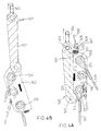
- FIGS 4A and 4B an alternative embodiment of the coupling mechanism according to the invention has been shown.
- the coupling mechanism 500 is herein formed by an oblong plate 501 and two parallel plates 502, hingeably connected to each other by means of hinges 505.
- the plate 501 herein fits between both plates 502.
- the depiction of figure 9A should be considered as a midsection.
- the plate 501 On the upper end the plate 501 is connected to shackle 504 by means of pin 503, a penetration anchor line being attached to said shackle.
- the plates 501 and 502 are also attached to each other, by means of an eye pin 508 projecting through a hole in transverse plate 506, which transverse plate connects both plates 502, and a hole provided in a transverse plate 507 in a plate 501, said eye pin being secured with breaking pin 519.
- a shackle 509 is attached to the eye of eye pin 508, to which shackle in its turn the thimble-shaped lower end of auxiliary line 510 is attached.
- Both plates 502 are also connected to each other by means of transverse pins 511, 512 and 513.
- Thimbles 514 and 515 have been placed around two of these transverse pins, which are therefore confined in lateral direction by both plates 502.
- Thimble 514 is the upper end of shank wire 517
- thimble 515 is the upper end of shank wire 518. It will be understood that these shank wires represent pairs of shank wires and are attached at the front and the rear respectively of the fluke of the anchor (not shown).
Landscapes
- Chemical & Material Sciences (AREA)
- Engineering & Computer Science (AREA)
- Combustion & Propulsion (AREA)
- Mechanical Engineering (AREA)
- Ocean & Marine Engineering (AREA)
- Piles And Underground Anchors (AREA)
- Artificial Fish Reefs (AREA)
- Tents Or Canopies (AREA)
- Surgical Instruments (AREA)
- Valve Device For Special Equipments (AREA)
- Iron Core Of Rotating Electric Machines (AREA)
Abstract
Description
- The application relates to an anchor comprising a fluke and a shank, formed by at least one pair of wires, lines or stays, such as cables or chains, attached onto the fluke with their lower ends at locations which are spaced from each other in longitudinal direction of the fluke and being connected to a coupling mechanism with their upper end at locations spaced from each other, said coupling mechanism being itself provided with means for connection to a penetration-anchor line, the coupling mechanism being provided with means, operated by remote control, for displacing or adjusting the upper ends of the shank wires relative to each other.
- The advantage of such an anchor is that the non-rigid shank, and with it the penetration-anchor line, can be adjusted under several angles relative to the penetrated fluke. When the anchor, after having served it purpose, is no longer required at a certain location and when it is desirable the use the same anchor at a different location, the angle between shank and fluke may be enlarged and the penetration-anchor line, which has also been used for the anchoring, can be brought into for instance a more vertical position, in which a tensile force exterted on the anchor line results in the fluke moving in an obliquely upwards direction through the anchoring soil, until the fluke leaves the anchoring base. It will also be possible, after penetration of the fluke in the anchoring base, to swing the shank wires and with this the shank relative to the fluke in such a way, that the fluke is suitable to take part in a vertical anchoring system. For this purpose the fluke need not be adapted, yet some provisions need to be made between the upper ends of the shank wires and the lower end of the penetration-anchor line, that is to say in the coupling mechanism.
- The anchor preferably comprises a coupling mechanism, having a movable connecting member, such as one or more oblong, parallel plates, wires or chains, to which the upper ends of both shank wires have been secured and comprising displacement means for swinging the connecting member in a vertical plane.
- The operatable means preferably comprise two flexible connecting lines of unequal length, being connected with their lower ends to the connecting member at locations that are spaced from each other, and being connected with their upper ends to a coupling member at locations that are displacable relative to each other in direction of pull by means of remote control means, said coupling member being itself connected with its upper end to the lower end of the penetration-anchor line.
- The coupling member herein preferably comprises two or more female spaces or seats, which open substantially in the direction of pull, away from the fluke, and are spaced in direction of pull and in which a male member, such as a pin or cam, situated on or near the upper end of the longest connecting line, may come to rest in a removable manner, the operating means being adapted to control the position of the male member.
- The remote control means can comprise an auxiliary line, put around a pin, to be put into the seat by means of for instance a thimble.
- An advantageous, compact and simple embodiment of the coupling mechanism according to the invention is one in which the movable connecting member comprises a first connecting part and a second connecting part, being hingedly connected to each other on one end and being connected to each other on their other end by means of a connection which can be disconnected by means of remote control means, the first connecting part being provided with the means for connection with the pentration-anchor line and the second connecting part being provided with means, being spaced from each other, for connection with the upper ends of the shank wires. By disconnecting the two connecting parts on their one end they can, under continued pull on the penetration anchor line, as it were swing open relative to each other into for instance a mutual angle of 180°. During this movement, the location of the means for connection with the upper ends of the shank wire will be interchanged and thereby the angle of the shank relative to the fluke.
- Preferably, the first connecting part and/or the second connecting part are herein formed by an oblong plate or plates.
- Preferably, the disconnectable connection is formed by a tenon and mortise connection, the tenon being connected to the lower end of an auxiliary line. By simply pulling the auxiliary line, the tenon is removed from the connection and the first and second connecting parts can jump open.
- In order to have more possibilities in the choice of the shank angle prior to paying out the anchor, the second connecting part is preferably provided with more than two interspaced means for connection with the upper ends of the shank wires.
- The invention will now be described in more detail on the basis of the embodiments of the coupling mechanism according to the invention, shown in the accompanying figures and both serving merely as examples. The following is shown in:
- figures 1A-C: the starting position, the intermediate position and the final position of a coupling mechanism according to the invention, with which the angle of a stay shank may be changed relative to an anchor fluke;
- figure 2: a schematic representation of the penetration of a fluke and the adjustment thereof for a vertical-anchoring system for a TLP, wherein use can be made of the coupling mechanism of figures 6A-6C;
- figures 3A-3C: some views of the coupling member of the example of a coupling mechanism according to the invention represented in figures 6A-6C; and
- figures 4A en 4B: the folded and the extended position, respectively, of an alternative embodiment of the coupling mechanism according to the invention.
- Figures 1A-1C show the mechanism according to the application by which, in case of a penetrated fluke, the shank angle relative to the fluke can be altered by means of remote control. The anchor as shown here comprises a
fluke 200, to which a pair offront shank cables 202 and a pair ofrear shank cables 203 have been attached with their lower ends. Theupper ends shank wires plate 204. This connectingplate 204 is provided with two eyes, in which twoshackles upper ends shank cables lower ends cables shackles cable 210 is herein longer than the connectingcable 209. - A
coupling member 220 is situated above thecables plate assembly 221 and amovable coupling element 222. Theplate assembly 221 comprises twoparallel plates notches plate assembly 221 thethimble 212 is attached to the upper end of the connectingline 209 by means of apin 225 andshackle 226. The lower end of the penetration-anchor line 230, in the shape ofthimble 231, is attached to the upper end of theplate assembly 221 by means ofpin 226 andshackle 228. - The
displacable coupling member 222 here consists of twoparallel plates 222a and 222b, connected to each other by means of anupper pin 224 and alower pin 223. The distance between these twopins coupling member 222 can shift over theplate assembly 221. On its upper end, the connectingcable 210 is attached withthimble 214 to thepin 223 and thereby to thecoupling member 221. - Figure 3A shows the
plate assembly 221 and thecoupling member 221 separately in side view. In figure 3B, both parts are shown in perspective, but now in the position, in which the coupling member rests in theseat 232. Figure 8C provides a front view of both parts with shackles, the coupling member resting in theseat 233. - In the situation represented in figure 1A, the
upper pin 224 of thecoupling member 221 rests in thelower seat 231 and, as a consequence of the ratio in length between the connectingcables cable 209 is taut. The tensile force is consequently transferred fromanchor line 230, to theplate assembly 221, to connectingcable 209 and from there to the connectingplate 204. In figure 1A, the anchor has a configuration in which it is suitable to be pulled into sandy soils. The situation in figure 1A will thus occur during penetration. For this purpose, reference can also be made to the sketch of figure 2, in which it can be seen how thefluke 200 is pulled into thesoil 300 by the penetration-anchor line 230, along thepath 301. On the right-hand end of thispath 301 the situation shown in figure 1B has been achieved. Then, theauxiliary cable 234 is pulled, of which thelower end 235, in this case a thimble, is attached to thepin 224 of thecoupling member 222. By pulling theauxiliary cable 234, for instance from the object to the anchored or from an auxiliary vessel, thepin 224 will be pulled up out of theseat 233 and can then be pulled up along the side edges of theplates seat 232. Theauxiliary cable 232 is herein advantageously guided by theshackle 228. When thepin 224 is moved upwards, thecoupling member 222 will be moved upwards over and aroundplate assembly 221 and thereby also thepin 223. As a result, the connectingcable 210 will become taut and exert a tensile force on, seen in the drawing, the left-hand portion of the connectingplate 204, so that the latter will twist clockwise. Herein a tensile force is also exerted in therear shank cables 203, so that the fluke will also be rotated clockwise, which has been schematically represented on the right-hand side of figure 2. - Finally, the situation represented in figure 1C is achieved, in which the
pin 223 has come to rest in theseat 232 and the fluke has attained an ideal position for a vertical anchoring system as in figure 2 for theTLP 302. By means of thecables 230, the TLP 302 is pre-tensioned relative to the water-level 303. - If desired, the
pin 224 can also be connected to an auxiliary line, extending to the floating object. By means of this auxiliary line, not shown, thecoupling member 222 may be lifted on the left-hand side, after theanchor line 230 has been relaxed somewhat, in order to achieve the exit of thepin 223 out theseat 232, the result of that being that thepin 224 is once again brought into theseat 233 by means of the tensile force exerted on theanchor line 230. In this position, pulling thefluke 200 out of the soil is made easier. - In figures 4A and 4B, an alternative embodiment of the coupling mechanism according to the invention has been shown. The
coupling mechanism 500 is herein formed by anoblong plate 501 and twoparallel plates 502, hingeably connected to each other by means ofhinges 505. Theplate 501 herein fits between bothplates 502. The depiction of figure 9A should be considered as a midsection. - On the upper end the
plate 501 is connected toshackle 504 by means ofpin 503, a penetration anchor line being attached to said shackle. On that same end, theplates eye pin 508 projecting through a hole intransverse plate 506, which transverse plate connects bothplates 502, and a hole provided in atransverse plate 507 in aplate 501, said eye pin being secured with breakingpin 519. Ashackle 509 is attached to the eye ofeye pin 508, to which shackle in its turn the thimble-shaped lower end ofauxiliary line 510 is attached. - Both
plates 502 are also connected to each other by means oftransverse pins Thimbles plates 502.Thimble 514 is the upper end ofshank wire 517 andthimble 515 is the upper end ofshank wire 518. It will be understood that these shank wires represent pairs of shank wires and are attached at the front and the rear respectively of the fluke of the anchor (not shown). - When now, after sufficient penetration of the anchor, the
auxiliary line 510 is pulled, thepin 508 will be pulled out of the holes in theparts plates shackle 504 will result in the breaking of thebreaking pin 510 and in theplates hinge 505. Finally, the situation represented in figure 9B is achieved, in which thetransverse pin 511 and therewith thethimble 514 are now situated higher than thetransverse pin 512 and thethimble 515.
Claims (10)
- Anchor, comprising a fluke and a shank, formed by at least one pair of wires, lines or stays, such as cables or chains, attached onto the fluke with their lower ends at locations which are spaced from each other in longitudinal direction of the fluke and said cables or chains being connected to a coupling mechanism with their upper end at locations spaced from each other, said coupling mechanism being itself provided with means for connection to a penetration anchor line, the coupling mechanism being provided with means, operable by remote control, for displacing or adjusting the upper ends of the shank wires relative to each other.
- Anchor according to claim 1, comprising a coupling mechanism, which comprises a movable connecting member, such as one or more oblong, parellel plates, wires or chains, to which the upper ends of both shank wires have been secured and comprising displacement means for swinging the connecting member in a vertical plane.
- Anchor according to claim 2, the operable means preferably comprising two flexible connecting lines of unequal length, being connected with their lower ends to the connecting member at locations that are spaced from each other, and being connected with their upper ends to a coupling member at locations that are displacable relative to each other in direction of pull by means of remote control means, said coupling member being itself connected with its upper end to the lower end of the penetration-anchor line.
- Anchor according to claim 3, the coupling member comprising two or more female spaces or seats, which open substantially in the direction of pull, away from the fluke, and are spaced in direction of pull and in which a male member, such as a pin or cam, situated on or near the upper end of the longest connecting line, may come to rest in a removable manner, the control means being adapted to control the position of the male member.
- Anchor according to claim 4, the control means comprising an auxiliary line, put around a member, such as the pin, to be put into the seats by means of for instance a thimble.
- Anchor according to claim 2, the movable connecting member comprising a first connecting part and a second connecting part, being hingedly connected to each other on one end and on their other end being connected to each other by means of a connection which can be disconnected by means of remote control means, the first connecting part being provided with the means for connection with the penetration-anchor line and the second connecting part being provided with means, being spaced from each other, for connection with the upper ends of the shank wires.
- Anchor according to claim 6, the first connecting part and/or the second connecting part being formed by an oblong plate or plates.
- Anchor according to claim 6 or 7, the disconnectable connection being formed by a tenon and mortise connection, the tenon being connected to the lower end of an auxiliary line.
- Anchor according to claim 6, 7 or 8, the second connecting part being provided with more than two means, spaced from each other, for connection with the upper ends of the shank wires.
- Coupling mechanism apparently suitable for use with the anchor according to any one of the claims 1-9.
Applications Claiming Priority (3)
| Application Number | Priority Date | Filing Date | Title |
|---|---|---|---|
| NL9202083 | 1992-12-01 | ||
| NL9202083A NL9202083A (en) | 1992-12-01 | 1992-12-01 | Anchor flow. |
| EP94903135A EP0670795B1 (en) | 1992-12-01 | 1993-12-01 | Anchor fluke |
Related Parent Applications (2)
| Application Number | Title | Priority Date | Filing Date |
|---|---|---|---|
| EP94903135A Division EP0670795B1 (en) | 1992-12-01 | 1993-12-01 | Anchor fluke |
| EP94903135.5 Division | 1994-06-09 |
Publications (3)
| Publication Number | Publication Date |
|---|---|
| EP0802111A2 true EP0802111A2 (en) | 1997-10-22 |
| EP0802111A3 EP0802111A3 (en) | 1998-01-14 |
| EP0802111B1 EP0802111B1 (en) | 2002-04-17 |
Family
ID=19861577
Family Applications (2)
| Application Number | Title | Priority Date | Filing Date |
|---|---|---|---|
| EP94903135A Expired - Lifetime EP0670795B1 (en) | 1992-12-01 | 1993-12-01 | Anchor fluke |
| EP97201975A Expired - Lifetime EP0802111B1 (en) | 1992-12-01 | 1993-12-01 | Handling system for anchor |
Family Applications Before (1)
| Application Number | Title | Priority Date | Filing Date |
|---|---|---|---|
| EP94903135A Expired - Lifetime EP0670795B1 (en) | 1992-12-01 | 1993-12-01 | Anchor fluke |
Country Status (7)
| Country | Link |
|---|---|
| US (1) | US5640921A (en) |
| EP (2) | EP0670795B1 (en) |
| AU (1) | AU5719694A (en) |
| BR (1) | BR9307561A (en) |
| NL (1) | NL9202083A (en) |
| NO (2) | NO305645B1 (en) |
| WO (1) | WO1994012386A2 (en) |
Cited By (3)
| Publication number | Priority date | Publication date | Assignee | Title |
|---|---|---|---|---|
| WO2000044613A1 (en) * | 1999-01-26 | 2000-08-03 | Petróleo Brasileiro S.A. - Petrobras | Anchor |
| WO2006062397A1 (en) * | 2004-12-07 | 2006-06-15 | Vrijhof Ankers Beheer B.V. | Device for an anchor with a retrieval provision |
| GB2495593A (en) * | 2011-10-12 | 2013-04-17 | Brupat Ltd | Marine anchor with a fluke and a shank having a pivotal and remotely lockable connection |
Families Citing this family (7)
| Publication number | Priority date | Publication date | Assignee | Title |
|---|---|---|---|---|
| NL1000583C2 (en) | 1995-06-16 | 1996-12-17 | Vrijhof Ankers Beheer Bv | Anchor flow. |
| NL1005353C2 (en) | 1997-02-24 | 1998-08-26 | Vrijhof Ankers Beheer Bv | Anchor and decoupling method therefor. |
| US6009825A (en) * | 1997-10-09 | 2000-01-04 | Aker Marine, Inc. | Recoverable system for mooring mobile offshore drilling units |
| BR9903032A (en) * | 1999-02-25 | 2001-10-09 | Rio Offshore Ltda | dea vertical loading anchor |
| ES2365397T3 (en) * | 2000-04-27 | 2011-10-03 | Stevlos B.V. | ANCHOR WITH NAIL THAT HAS A SUPERIOR SURFACE THAT INCLUDES SIDE PLANS INCLUDED BELOW. |
| GB201006362D0 (en) * | 2010-04-16 | 2010-06-02 | Brupat Ltd | Offshore marine anchor |
| NL2015665B1 (en) * | 2015-10-27 | 2017-05-24 | Stevlos Bv | Anchor. |
Family Cites Families (12)
| Publication number | Priority date | Publication date | Assignee | Title |
|---|---|---|---|---|
| US1838745A (en) * | 1928-10-29 | 1931-12-29 | Charles H Croney | Marsh anchor |
| DE2352144A1 (en) * | 1973-10-17 | 1975-04-24 | Wolf Klemm | Ships non snagging sea anchor - without open ended flukes and with hinged throat about anchor shaft |
| GB1513453A (en) * | 1975-06-13 | 1978-06-07 | Peter Bruce | Anchors |
| NL168768C (en) * | 1976-08-05 | 1982-05-17 | New Hook Anchors Holding | ANCHOR. |
| GB1590627A (en) * | 1976-09-22 | 1981-06-03 | Mcalpine & Sons Ltd Sir Robert | Anchor |
| DE2929495A1 (en) * | 1979-07-20 | 1981-02-05 | Wolf Klemm | Tubular anchor - has hollow-cylinder crown with weight unbalanced for stable position with prongs digging edge downwards |
| NL8400890A (en) * | 1984-03-21 | 1985-10-16 | Ir M G Gout | Marine anchor with pointed triangular plate and broad end - has three cables or chains secured near point on sides by swivel eyes and converging to cable or chain fixture |
| SE447723C (en) * | 1985-05-03 | 1989-10-16 | Agge Sahlberg | SEA ANCHOR MENTIONED FOR SUBMISSION LONG AND AN INCLUDING LAY |
| US4781142A (en) * | 1985-05-21 | 1988-11-01 | Cheung Maxwell C | High performance marine anchor |
| ATE60741T1 (en) * | 1986-06-25 | 1991-02-15 | Norena Alfonso Garcia | SYSTEM FOR RELEASING AN ANCHOR STUCK TO THE SEA BED. |
| JPS63315395A (en) * | 1987-06-19 | 1988-12-23 | Satoru Kobayashi | Release device caught anchor |
| GB2286168B (en) * | 1991-08-16 | 1996-02-21 | Vrijhof Ankers Beheer Bv | Anchor |
-
1992
- 1992-12-01 NL NL9202083A patent/NL9202083A/en not_active Application Discontinuation
-
1993
- 1993-12-01 EP EP94903135A patent/EP0670795B1/en not_active Expired - Lifetime
- 1993-12-01 WO PCT/NL1993/000257 patent/WO1994012386A2/en not_active Ceased
- 1993-12-01 EP EP97201975A patent/EP0802111B1/en not_active Expired - Lifetime
- 1993-12-01 BR BR9307561A patent/BR9307561A/en not_active IP Right Cessation
- 1993-12-01 AU AU57196/94A patent/AU5719694A/en not_active Abandoned
- 1993-12-01 US US08/446,774 patent/US5640921A/en not_active Expired - Lifetime
-
1995
- 1995-05-31 NO NO952156A patent/NO305645B1/en not_active IP Right Cessation
-
1998
- 1998-07-15 NO NO19983274A patent/NO310104B1/en not_active IP Right Cessation
Non-Patent Citations (1)
| Title |
|---|
| None |
Cited By (10)
| Publication number | Priority date | Publication date | Assignee | Title |
|---|---|---|---|---|
| WO2000044613A1 (en) * | 1999-01-26 | 2000-08-03 | Petróleo Brasileiro S.A. - Petrobras | Anchor |
| US6240870B1 (en) | 1999-01-26 | 2001-06-05 | Petroleo Brasileiro S.A. - Petrobras | Anchor |
| WO2006062397A1 (en) * | 2004-12-07 | 2006-06-15 | Vrijhof Ankers Beheer B.V. | Device for an anchor with a retrieval provision |
| US7475650B2 (en) | 2004-12-07 | 2009-01-13 | Rijhof Ankers Beheer B.V. | Device for an anchor with a retrieval provision |
| CN100545034C (en) * | 2004-12-07 | 2009-09-30 | 斯特弗劳斯有限公司 | Devices for anchors and anchors provided with such devices |
| NO337951B1 (en) * | 2004-12-07 | 2016-07-18 | Stevlos Bv | Device for an anchor with a retrieval fit |
| GB2495593A (en) * | 2011-10-12 | 2013-04-17 | Brupat Ltd | Marine anchor with a fluke and a shank having a pivotal and remotely lockable connection |
| WO2013054087A1 (en) | 2011-10-12 | 2013-04-18 | Brupat Limited | Improved offshore marine anchor |
| GB2495593B (en) * | 2011-10-12 | 2014-03-19 | Brupat Ltd | Marine anchor with a fluke and a shank having a pivotal and remotely lockable connection |
| US9233738B2 (en) | 2011-10-12 | 2016-01-12 | Brupat Limited | Offshore marine anchor |
Also Published As
| Publication number | Publication date |
|---|---|
| NL9202083A (en) | 1994-07-01 |
| WO1994012386A2 (en) | 1994-06-09 |
| NO952156L (en) | 1995-08-01 |
| EP0670795B1 (en) | 1998-02-04 |
| BR9307561A (en) | 1999-06-01 |
| WO1994012386A3 (en) | 1994-09-15 |
| NO952156D0 (en) | 1995-05-31 |
| AU5719694A (en) | 1994-06-22 |
| NO983274L (en) | 1995-08-01 |
| NO305645B1 (en) | 1999-07-05 |
| NO983274D0 (en) | 1998-07-15 |
| EP0802111B1 (en) | 2002-04-17 |
| NO310104B1 (en) | 2001-05-21 |
| US5640921A (en) | 1997-06-24 |
| EP0802111A3 (en) | 1998-01-14 |
| EP0670795A1 (en) | 1995-09-13 |
Similar Documents
| Publication | Publication Date | Title |
|---|---|---|
| EP0802111B1 (en) | Handling system for anchor | |
| FI71701B (en) | Ankare | |
| KR100491778B1 (en) | Underwater self-aligning fairlead latch device for mooring a structure at sea | |
| EP3126212B1 (en) | Chain stopper | |
| DE2115471C3 (en) | buckle | |
| CN112689595B (en) | Chain tensioner with chain switch device | |
| NL9220023A (en) | Anchor for deep-water drilling platform - has hinged joint located between centre of gravity of fluke and its front end | |
| EP0387267B1 (en) | Tensioning device | |
| US4655004A (en) | Device for automatically locking a hatchway panel in the open or closed position | |
| CN1066111C (en) | Stopping and locking devices for anchor chains and cables | |
| US6435121B2 (en) | Sliding shoe fairlead with an integrated chain stopper | |
| US3774361A (en) | Shore line boat anchor | |
| GB2631137A (en) | Submersible mooring pulley having separable chain wheel | |
| WO1994012386A9 (en) | Anchor fluke | |
| DE2508764A1 (en) | CROWN STOPPER | |
| US4026522A (en) | Post pulling apparatus | |
| US20080197548A1 (en) | Self-retracting extension limiting device | |
| US3059607A (en) | Anchor | |
| US7475650B2 (en) | Device for an anchor with a retrieval provision | |
| KR102641410B1 (en) | submersible mooring pulley for offshore structure mooring system | |
| EP2220393A1 (en) | Self-retracting extension limiting device | |
| CA2224595A1 (en) | Locking member device for tow pins on a vessel | |
| DE2336117C3 (en) | Notching device | |
| GB2623231A (en) | Submersible mooring pulley for offshore structure mooring system | |
| DE2917023B2 (en) | Cable hoist with gate hanger and built-in slack rope safety device for a ceiling link or roller door |
Legal Events
| Date | Code | Title | Description |
|---|---|---|---|
| PUAI | Public reference made under article 153(3) epc to a published international application that has entered the european phase |
Free format text: ORIGINAL CODE: 0009012 |
|
| AC | Divisional application: reference to earlier application |
Ref document number: 670795 Country of ref document: EP |
|
| AK | Designated contracting states |
Kind code of ref document: A2 Designated state(s): FR GB IE IT MC NL |
|
| PUAL | Search report despatched |
Free format text: ORIGINAL CODE: 0009013 |
|
| AK | Designated contracting states |
Kind code of ref document: A3 Designated state(s): FR GB IE IT MC NL |
|
| 17P | Request for examination filed |
Effective date: 19971217 |
|
| 17Q | First examination report despatched |
Effective date: 20000705 |
|
| GRAG | Despatch of communication of intention to grant |
Free format text: ORIGINAL CODE: EPIDOS AGRA |
|
| GRAG | Despatch of communication of intention to grant |
Free format text: ORIGINAL CODE: EPIDOS AGRA |
|
| GRAG | Despatch of communication of intention to grant |
Free format text: ORIGINAL CODE: EPIDOS AGRA |
|
| GRAH | Despatch of communication of intention to grant a patent |
Free format text: ORIGINAL CODE: EPIDOS IGRA |
|
| REG | Reference to a national code |
Ref country code: GB Ref legal event code: IF02 |
|
| GRAH | Despatch of communication of intention to grant a patent |
Free format text: ORIGINAL CODE: EPIDOS IGRA |
|
| GRAA | (expected) grant |
Free format text: ORIGINAL CODE: 0009210 |
|
| AC | Divisional application: reference to earlier application |
Ref document number: 670795 Country of ref document: EP |
|
| AK | Designated contracting states |
Kind code of ref document: B1 Designated state(s): FR GB IE IT MC NL |
|
| REG | Reference to a national code |
Ref country code: IE Ref legal event code: FG4D |
|
| ET | Fr: translation filed | ||
| PLBE | No opposition filed within time limit |
Free format text: ORIGINAL CODE: 0009261 |
|
| STAA | Information on the status of an ep patent application or granted ep patent |
Free format text: STATUS: NO OPPOSITION FILED WITHIN TIME LIMIT |
|
| 26N | No opposition filed |
Effective date: 20030120 |
|
| REG | Reference to a national code |
Ref country code: GB Ref legal event code: 732E Free format text: REGISTERED BETWEEN 20090129 AND 20090204 |
|
| NLS | Nl: assignments of ep-patents |
Owner name: STEVLOS B.V. Effective date: 20090115 |
|
| REG | Reference to a national code |
Ref country code: FR Ref legal event code: TP |
|
| PG25 | Lapsed in a contracting state [announced via postgrant information from national office to epo] |
Ref country code: IT Free format text: LAPSE BECAUSE OF NON-PAYMENT OF DUE FEES Effective date: 20091201 |
|
| PGRI | Patent reinstated in contracting state [announced from national office to epo] |
Ref country code: IT Effective date: 20110616 |
|
| PGFP | Annual fee paid to national office [announced via postgrant information from national office to epo] |
Ref country code: IE Payment date: 20121123 Year of fee payment: 20 Ref country code: MC Payment date: 20121108 Year of fee payment: 20 |
|
| PGFP | Annual fee paid to national office [announced via postgrant information from national office to epo] |
Ref country code: IT Payment date: 20121123 Year of fee payment: 20 Ref country code: GB Payment date: 20121128 Year of fee payment: 20 |
|
| PGFP | Annual fee paid to national office [announced via postgrant information from national office to epo] |
Ref country code: NL Payment date: 20121228 Year of fee payment: 20 |
|
| PGFP | Annual fee paid to national office [announced via postgrant information from national office to epo] |
Ref country code: FR Payment date: 20130516 Year of fee payment: 20 |
|
| REG | Reference to a national code |
Ref country code: NL Ref legal event code: V4 Effective date: 20131201 |
|
| REG | Reference to a national code |
Ref country code: GB Ref legal event code: PE20 Expiry date: 20131130 |
|
| REG | Reference to a national code |
Ref country code: IE Ref legal event code: MK9A |
|
| PG25 | Lapsed in a contracting state [announced via postgrant information from national office to epo] |
Ref country code: IE Free format text: LAPSE BECAUSE OF EXPIRATION OF PROTECTION Effective date: 20131201 Ref country code: GB Free format text: LAPSE BECAUSE OF EXPIRATION OF PROTECTION Effective date: 20131130 |