EP0802151B1 - Flèche pour un appareil de levage - Google Patents
Flèche pour un appareil de levage Download PDFInfo
- Publication number
- EP0802151B1 EP0802151B1 EP97104014A EP97104014A EP0802151B1 EP 0802151 B1 EP0802151 B1 EP 0802151B1 EP 97104014 A EP97104014 A EP 97104014A EP 97104014 A EP97104014 A EP 97104014A EP 0802151 B1 EP0802151 B1 EP 0802151B1
- Authority
- EP
- European Patent Office
- Prior art keywords
- joint
- arm
- jib
- fact
- load
- Prior art date
- Legal status (The legal status is an assumption and is not a legal conclusion. Google has not performed a legal analysis and makes no representation as to the accuracy of the status listed.)
- Expired - Lifetime
Links
- 239000000463 material Substances 0.000 claims description 9
- 230000006835 compression Effects 0.000 claims description 8
- 238000007906 compression Methods 0.000 claims description 8
- 210000003128 head Anatomy 0.000 claims description 7
- 239000000725 suspension Substances 0.000 claims description 5
- 230000000694 effects Effects 0.000 claims description 2
- 239000002861 polymer material Substances 0.000 claims description 2
- 229920001169 thermoplastic Polymers 0.000 claims description 2
- 239000012858 resilient material Substances 0.000 description 5
- 239000012530 fluid Substances 0.000 description 3
- 238000004904 shortening Methods 0.000 description 3
- 238000010276 construction Methods 0.000 description 2
- 125000006850 spacer group Chemical group 0.000 description 2
- 238000013459 approach Methods 0.000 description 1
- 238000005452 bending Methods 0.000 description 1
- 238000006073 displacement reaction Methods 0.000 description 1
- 238000005553 drilling Methods 0.000 description 1
- 230000005489 elastic deformation Effects 0.000 description 1
- 230000005012 migration Effects 0.000 description 1
- 238000013508 migration Methods 0.000 description 1
- 238000005381 potential energy Methods 0.000 description 1
- 239000004416 thermosoftening plastic Substances 0.000 description 1
Images


Classifications
-
- B—PERFORMING OPERATIONS; TRANSPORTING
- B66—HOISTING; LIFTING; HAULING
- B66C—CRANES; LOAD-ENGAGING ELEMENTS OR DEVICES FOR CRANES, CAPSTANS, WINCHES, OR TACKLES
- B66C23/00—Cranes comprising essentially a beam, boom, or triangular structure acting as a cantilever and mounted for translatory of swinging movements in vertical or horizontal planes or a combination of such movements, e.g. jib-cranes, derricks, tower cranes
- B66C23/005—Cranes comprising essentially a beam, boom, or triangular structure acting as a cantilever and mounted for translatory of swinging movements in vertical or horizontal planes or a combination of such movements, e.g. jib-cranes, derricks, tower cranes with balanced jib, e.g. pantograph arrangement, the jib being moved manually
-
- B—PERFORMING OPERATIONS; TRANSPORTING
- B66—HOISTING; LIFTING; HAULING
- B66C—CRANES; LOAD-ENGAGING ELEMENTS OR DEVICES FOR CRANES, CAPSTANS, WINCHES, OR TACKLES
- B66C23/00—Cranes comprising essentially a beam, boom, or triangular structure acting as a cantilever and mounted for translatory of swinging movements in vertical or horizontal planes or a combination of such movements, e.g. jib-cranes, derricks, tower cranes
- B66C23/02—Cranes comprising essentially a beam, boom, or triangular structure acting as a cantilever and mounted for translatory of swinging movements in vertical or horizontal planes or a combination of such movements, e.g. jib-cranes, derricks, tower cranes with non-adjustable and non-inclinable jibs mounted solely for slewing movements
- B66C23/022—Pivot axis common with column
-
- B—PERFORMING OPERATIONS; TRANSPORTING
- B66—HOISTING; LIFTING; HAULING
- B66C—CRANES; LOAD-ENGAGING ELEMENTS OR DEVICES FOR CRANES, CAPSTANS, WINCHES, OR TACKLES
- B66C23/00—Cranes comprising essentially a beam, boom, or triangular structure acting as a cantilever and mounted for translatory of swinging movements in vertical or horizontal planes or a combination of such movements, e.g. jib-cranes, derricks, tower cranes
- B66C23/04—Cranes comprising essentially a beam, boom, or triangular structure acting as a cantilever and mounted for translatory of swinging movements in vertical or horizontal planes or a combination of such movements, e.g. jib-cranes, derricks, tower cranes with jibs the effective length of which is variable in operation, e.g. longitudinally displaceable, extensible
-
- B—PERFORMING OPERATIONS; TRANSPORTING
- B66—HOISTING; LIFTING; HAULING
- B66C—CRANES; LOAD-ENGAGING ELEMENTS OR DEVICES FOR CRANES, CAPSTANS, WINCHES, OR TACKLES
- B66C23/00—Cranes comprising essentially a beam, boom, or triangular structure acting as a cantilever and mounted for translatory of swinging movements in vertical or horizontal planes or a combination of such movements, e.g. jib-cranes, derricks, tower cranes
- B66C23/62—Constructional features or details
- B66C23/64—Jibs
Definitions
- the invention relates to a boom for a lifting device, which consists of an inner Partial arm is formed, the one end pivotable about a vertical pivot pin is stored, and the other by means of a joint with a vertical Swivel axis is connected to an outer arm, which is at its free End - immediately, or with the interposition of other components Load suspension device carries.
- a boom is from the utility model DE-U-9 012 587 already known.
- Such booms are often used in small lifting devices, in particular handheld manipulators used.
- the fact that the outer arm pivoted almost 360 ° around the joint that connects it to the inner arm can cover the load handler in this version a very large area.
- the attached load is somewhat larger, then it will become again move from the straight to the angled position. Is she however, less, it will automatically move from the angled to the move extended position. And there is a very special disadvantage with this version when the outer arm from the extended position in is brought into a position swiveled through 180 °, in which the two partial arms lie on top of each other. The outer arm would then be in this position raised such an amount that it is self-employed from here would move into the extended position.
- the invention has for its object to the disadvantages described avoid and create a solution with minimal design effort, where the load stops in any position of the outer arm and also from every position of the outer arm with constant low force can be moved.
- a possible constructive training can be achieved in that the joint connecting two sub-arms two at an axial distance from each other arranged pivot bearing having at least one, surrounding a pin Have outer part, wherein at least the outer part of a pivot bearing in an elongated hole of a housing surrounding it is mounted, and wherein the Elongated hole extends in the direction of the longitudinal axis of the inner arm and in the Transverse direction corresponds to the outer dimension of the outer part while it is in Longitudinal direction exceeds this and the cavity between the outer part and slot is filled with an elastically resilient material.
- Manipulators often use a design for the boom in which the inner arm is a push rod arranged above or below it has and wherein the partial arm and the push rod at both ends by means of joints with horizontal axes on the one hand with a support head on the the sleeve surrounding the pivot pin and on the other hand with a joint surrounding housing are connected.
- This construction is called a parallelogram boom.
- the resilient element can e.g. by two compression springs be formed, which are inserted into a longitudinal bore of the push rod and themselves support them with their ends facing away from projections of the bore, while their facing ends are longitudinally slidable on a fret pin in the longitudinal bore. If stretched Position of the two arms on the load suspension device acts a load, so the one compression spring is loaded and compressed by a certain amount, which results in an extension of the overhead or a shortening of the push rod below. On the other hand, the outer arm is out this position swiveled back by 180 °, then the other compression spring compressed, which leads to a shortening of the overhead or to a Extension of the push rod below leads. In both cases achieved that the deviation of the longitudinal axis of the connecting the two arms Joint in the two positions described will be just as large as in the 90 ° angled positions.
- the resilient elements can be made of a polymer material, in particular a thermoplastic.
- Fig. 1 is on a pivot pin 1 at the top of a column 2 Sleeve 3 pivotally mounted, with which an inner arm 4 is fixedly connected. At the free end of this arm 4 is the outer by means of a joint 5 Arm 6 pivotally mounted.
- This has a guide at its free end 7 for the vertically movable storage of the telescopic rod 8 on her lower end carries a load hook 9.
- a lifting drive 10 is provided, which by means of a rope 11 with the Telescopic rod is connected.
- FIG. 2 The top view of this lifting device shown in Fig. 2 shows that the inner arm 4 can be pivoted about the pivot pin 3 that the Joint 5 describes the circular arc 12 shown in dashed lines.
- the outer Partial arm 6 can also be pivoted about the joint 5, the Telescopic rod 8 describes the dashed arc 13.
- the outer arm 6 the extreme positions designated by the letters A, B, C and D. take in.
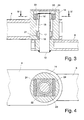
- a housing 14 is connected to the free end of the inner partial arm 4, in which a pin 15, which is connected to the outer partial arm 6, is pivotally mounted.
- the inner rings are on the pin 15 16 and 17 of two slide bearings located at an axial distance from one another arranged. These are through spacer sleeves 18 and 19 and a snap ring 20 fixed on the pin 15.
- the inner ring 17 forms, together with the outer ring 21, a joint bearing spherical sliding surfaces, which allows a pivoting movement of the pin 15.
- the inner ring 16 cooperates with an outer part 22 which, as shown in FIG. 4, has a has a square outer contour.
- This outer part 22 is in an elongated hole 23 of the housing 14 used, the dimensions of which are selected so that the Outer part in the direction of the longitudinal axis of the inner arm 4 a displacement has, while it is guided without play in the transverse direction.
- the both sides of the Outer part 22 with respect to the elongated hole 23 are through one elastically compliant material 24 filled.
- Fig. 5 shows a variant of a lifting device in which a column 25 on her upper end a pivotally mounted on it about a pivot pin 50
- Sleeve 27 carries, with which a support head 26 is connected at its upper end.
- a support head 26 is connected at its upper end.
- the Housing 31 is connected at the Support head 26 .
- Parallel to the inner arm 29 and above a push rod 32 is arranged therefrom, which also has joints 33 and 34 on the one hand with the support head 26 and on the other hand with the housing 31 connected is.
- the sleeve 27 has a cantilevered bracket 35 which has a fluid cylinder 36 carries, the piston rod 37 engages the inner arm 29.
- a fluid cylinder 36 By pressing of the fluid cylinder 36 can be the inner partial arm 29 and the push rod 32 containing parallelogram arm and thus the housing 31 raised or be lowered.
- FIG. 2 The relationships shown in FIG. 2 are also one in this variant The same. Their negative effects can therefore also affect the same way as described there, e.g. that in Housing 31 located hinge forms in the same way as in FIG. 3rd and 4 is shown.
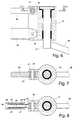
- Fig. 6 which is a longitudinal section through the Housing 31 shows is the bearing of the pin 40 that with the outer arm 38 is shown.
- Fig. 7 which is a cross section along line VII-VII of Fig. 6, is can be seen that the bolt 34 of a sleeve 41 from an elastically compliant Material is surrounded, which is inserted into an eye 42 of the push rod 32 is.
- the sleeve 41 can be elastic yield, causing an inclination of the pin 40 with respect to the vertical is achieved.
- a further variant is shown, in which on the pin 34 a head part 43 is mounted, in which a bolt 44 is screwed in has a collar 45 approximately in its center.
- This pin grips longitudinally in a bore 46 of the push rod 32 in which two compression springs 47 are housed, with their mutually facing ends on the federal government 45 rest and with their other ends on the one hand in the hole 46 used snap ring 48 and on the other hand at one closing the bore 46 Support thrust piece 49.
Landscapes
- Engineering & Computer Science (AREA)
- Mechanical Engineering (AREA)
- Jib Cranes (AREA)
- Load-Engaging Elements For Cranes (AREA)
- Forklifts And Lifting Vehicles (AREA)
Claims (6)
- Flèche pour un engin de levage, laquelle est composée d'un bras partiel intérieur (4, 29), qui, d'un côté, est monté de manière à pouvoir pivoter autour d'un tourillon de pivot vertical (1, 50) et, de l'autre côté, est relié au moyen d'une articulation (5) ayant un axe de pivotement vertical à un bras partiel extérieur (6, 38), qui, à son extrémité libre - directement ou avec montage intermédiaire d'autres éléments de construction - porte un dispositif de suspension de charge (9, 39), caractérisée en ce que des éléments du bras partiel intérieur (4, 29) ou de l'articulation (5), dans un plan qui contient le tourillon de pivot (1) et l'articulation (5), sont réalisés flexibles de telle sorte qu'il se crée sous l'effet d'une charge portée par le dispositif de suspension de charge (9, 39) un écart de l'axe longitudinal de l'articulation (5) par rapport à la verticale, qui correspond au moins à peu près à l'écart de cet axe longitudinal par rapport à la verticale qui se crée par suite de la déformation de torsion du bras partiel intérieur (4, 29), quand celui-ci forme un angle de 90° avec le bras partiel extérieur (6, 38).
- Flèche selon la revendication 1, caractérisée en ce que l'articulation (5) reliant les deux bras partiels (4, 6) présente deux coussinets de pivotement (16, 17 ; 21, 22) disposés à distance axiale l'un de l'autre, qui possèdent au moins une partie extérieure (22) entourant un tourillon (15), la partie extérieure (22) de l'un des coussinets de pivotement au moins étant montée dans un trou longitudinal (23) d'une enveloppe (14) entourant ce dernier, et le trou longitudinal (23) s'étendant dans la direction de l'axe longitudinal du bras partiel intérieur (4) et correspondant, dans le sens transversal, à la dimension extérieure de la partie extérieure (22), tandis qu'il dépasse celle-ci dans le sens longitudinal, et l'espace vide entre la partie extérieure (22) et le trou longitudinal (23) étant rempli avec un matériau élastique (24).
- Flèche selon la revendication 1, dans laquelle le bras partiel intérieur (29) présente une bielle (32) disposée au-dessus ou en dessous et parallèlement à celui-ci, le bras partiel (29) et la bielle (32) étant reliés à leurs deux extrémités au moyen d'articulations (28, 30 ; 33, 34) ayant des axes horizontaux, d'une part à une tête de support (26) située sur un manchon (27) entourant le tourillon de pivot et, d'autre part, à une enveloppe (31) entourant l'articulation, caractérisée en ce qu'un élément élastique (41, 47) est intégré dans la bielle (32).
- Flèche selon la revendication 3, caractérisée en ce que l'élément élastique est formé par deux ressorts de pression (47) qui sont montés dans un alésage longitudinal (46) de la bielle (32) et s'appuient là avec leurs extrémités détournées l'une de l'autre contre des saillies (48, 49) de l'alésage (46), tandis que leurs extrémités tournées l'une vers l'autre reposent contre un épaulement (45) d'un boulon (44) monté en déplacement longitudinal dans l'alésage longitudinal (46).
- Flèche selon la revendication 3, caractérisée en ce que les articulations ayant des axes horizontaux sont formées, sur la bielle, par des boulons d'appui (34), lesquels s'engagent dans des oeillets (42) les entourant, une douille (41) en matériau élastique étant insérée entre boulon (34) et oeillet (42) dans au moins une articulation.
- Flèche selon la revendication 2, 3 ou 5, caractérisée en ce que le matériau élastique est un matériau polymère, en particulier une matière synthétique thermoplastique.
Applications Claiming Priority (2)
| Application Number | Priority Date | Filing Date | Title |
|---|---|---|---|
| DE29606489U DE29606489U1 (de) | 1996-04-10 | 1996-04-10 | Ausleger für ein Hebegerät |
| DE29606489U | 1996-04-10 |
Publications (2)
| Publication Number | Publication Date |
|---|---|
| EP0802151A1 EP0802151A1 (fr) | 1997-10-22 |
| EP0802151B1 true EP0802151B1 (fr) | 2002-07-31 |
Family
ID=8022354
Family Applications (1)
| Application Number | Title | Priority Date | Filing Date |
|---|---|---|---|
| EP97104014A Expired - Lifetime EP0802151B1 (fr) | 1996-04-10 | 1997-03-11 | Flèche pour un appareil de levage |
Country Status (2)
| Country | Link |
|---|---|
| EP (1) | EP0802151B1 (fr) |
| DE (2) | DE29606489U1 (fr) |
Families Citing this family (5)
| Publication number | Priority date | Publication date | Assignee | Title |
|---|---|---|---|---|
| NL1016445C2 (nl) * | 2000-10-20 | 2002-04-23 | Staal En Constructiebouw Goere | Giekconstructie. |
| DE102013201768A1 (de) * | 2013-02-04 | 2014-08-07 | Krones Ag | Etikettiermaschine mit einer Hebevorrichtung |
| DE102015108725A1 (de) | 2015-06-02 | 2016-12-08 | Terex Cranes Germany Gmbh | Schwenklageranordnung mit einem Schwenkzapfen und mindestens einem Lagerbock und ein Montageverfahren hierfür |
| CN105417380A (zh) * | 2015-11-27 | 2016-03-23 | 河南新科起重机股份有限公司 | 一种新型智能化立柱摆臂起重机 |
| CN112919334A (zh) * | 2021-01-25 | 2021-06-08 | 四川省星光钢结构有限公司 | 一种用于装配式钢结构的移动组合装置 |
Family Cites Families (7)
| Publication number | Priority date | Publication date | Assignee | Title |
|---|---|---|---|---|
| GB1550974A (en) * | 1976-05-12 | 1979-08-22 | Fuchs Johannes | Apparatus for manual movement of a load |
| DE7713637U1 (de) * | 1977-04-29 | 1982-01-21 | Fa. Johannes Fuchs, 7257 Ditzingen | Vorrichtung zum manuellen bewegen von lasten |
| GB2188023A (en) * | 1986-03-18 | 1987-09-23 | Willem Marines De Weerd | Service boom |
| DE3717352A1 (de) * | 1986-08-20 | 1988-04-28 | Boecker Albert Gmbh & Co Kg | Mobiler lastaufzug |
| DE9012587U1 (de) * | 1990-09-03 | 1990-11-29 | Zasche Fördertechnik GmbH, 86720 Nördlingen | Handhabungs-Drehkran mit Knickausleger in Säulen- oder Deckenausführung |
| DE9101918U1 (de) * | 1991-02-19 | 1991-06-06 | Kühnezug Fördertechnik GmbH, 2000 Hamburg | Drehkran |
| DE4342715A1 (de) * | 1993-12-15 | 1995-06-22 | Zasche Foerdertechnik Gmbh | Handgeführter Manipulator |
-
1996
- 1996-04-10 DE DE29606489U patent/DE29606489U1/de not_active Expired - Lifetime
-
1997
- 1997-03-11 DE DE59707829T patent/DE59707829D1/de not_active Expired - Lifetime
- 1997-03-11 EP EP97104014A patent/EP0802151B1/fr not_active Expired - Lifetime
Also Published As
| Publication number | Publication date |
|---|---|
| DE29606489U1 (de) | 1996-06-20 |
| EP0802151A1 (fr) | 1997-10-22 |
| DE59707829D1 (de) | 2002-09-05 |
Similar Documents
| Publication | Publication Date | Title |
|---|---|---|
| DE3300306C2 (de) | Mehrteiliger Stangenkopf zur Verwendung bei Steuereinrichtungen zur Einstellung des Schnitthorizontes von Kohlenhobeln und dergleichen | |
| DE2912542C2 (fr) | ||
| AT502487A4 (de) | Dämpferanordnung | |
| EP0875421A1 (fr) | Elément de franchissement, comme hayon élévateur, élément d'un pont ou similaire | |
| EP0802151B1 (fr) | Flèche pour un appareil de levage | |
| DE2521722A1 (de) | Klammer | |
| DE69108164T2 (de) | Vorrichtung zum Anhängen eines Roboters an einen Unterstützungsbalken. | |
| DE68913526T2 (de) | Teleskop-stützvorrichtung. | |
| DE9317997U1 (de) | System zur Beeinflussung der Schwingungseigenschaft eines Ski | |
| DE3739254A1 (de) | Medizinisches, insbesondere chirurgisches instrument | |
| DE2604944A1 (de) | Umschlaganlage fuer fluide | |
| DE1287779B (fr) | ||
| DE3714079C2 (fr) | ||
| DE1811959A1 (de) | Zugbelastungsfreie Balgen-Gelenkverbindung | |
| DE69911970T2 (de) | Geh-Hilfsvorrichtung | |
| DE1934376A1 (de) | Ausleger-Stuetzpfeiler fuer Bergwerke oder unterirdische Baustellen | |
| DD147252A5 (de) | Kippbarer konverter | |
| DE195001C (fr) | ||
| DE4200391C2 (de) | Gelenkwagenheber | |
| DE1166433B (de) | Vorrichtung zur Anlenkung eines Greifers am Ausleger | |
| DE2319930A1 (de) | Vorpfaendvorrichtung mit schwenkbarer vorpfaendkappe und schwenkzylinder | |
| AT215721B (de) | Stützstrebe für die unteren Hubwerkslenker von Traktoren | |
| DE29620495U1 (de) | Pendelnd gelagerte Säule | |
| DE1484624C (de) | Planiergerät | |
| DE3837754C1 (fr) |
Legal Events
| Date | Code | Title | Description |
|---|---|---|---|
| PUAI | Public reference made under article 153(3) epc to a published international application that has entered the european phase |
Free format text: ORIGINAL CODE: 0009012 |
|
| 17P | Request for examination filed |
Effective date: 19970407 |
|
| AK | Designated contracting states |
Kind code of ref document: A1 Designated state(s): DE FR GB IT |
|
| GRAG | Despatch of communication of intention to grant |
Free format text: ORIGINAL CODE: EPIDOS AGRA |
|
| 17Q | First examination report despatched |
Effective date: 20010525 |
|
| GRAG | Despatch of communication of intention to grant |
Free format text: ORIGINAL CODE: EPIDOS AGRA |
|
| GRAH | Despatch of communication of intention to grant a patent |
Free format text: ORIGINAL CODE: EPIDOS IGRA |
|
| GRAG | Despatch of communication of intention to grant |
Free format text: ORIGINAL CODE: EPIDOS AGRA |
|
| GRAH | Despatch of communication of intention to grant a patent |
Free format text: ORIGINAL CODE: EPIDOS IGRA |
|
| GRAH | Despatch of communication of intention to grant a patent |
Free format text: ORIGINAL CODE: EPIDOS IGRA |
|
| RAP1 | Party data changed (applicant data changed or rights of an application transferred) |
Owner name: DEMAG CRANES & COMPONENTS GMBH |
|
| GRAA | (expected) grant |
Free format text: ORIGINAL CODE: 0009210 |
|
| AK | Designated contracting states |
Kind code of ref document: B1 Designated state(s): DE FR GB IT |
|
| REG | Reference to a national code |
Ref country code: GB Ref legal event code: FG4D Free format text: NOT ENGLISH |
|
| REF | Corresponds to: |
Ref document number: 59707829 Country of ref document: DE Date of ref document: 20020905 |
|
| GBT | Gb: translation of ep patent filed (gb section 77(6)(a)/1977) |
Effective date: 20020829 |
|
| ET | Fr: translation filed | ||
| PLBE | No opposition filed within time limit |
Free format text: ORIGINAL CODE: 0009261 |
|
| STAA | Information on the status of an ep patent application or granted ep patent |
Free format text: STATUS: NO OPPOSITION FILED WITHIN TIME LIMIT |
|
| 26N | No opposition filed |
Effective date: 20030506 |
|
| PGFP | Annual fee paid to national office [announced via postgrant information from national office to epo] |
Ref country code: GB Payment date: 20040303 Year of fee payment: 8 |
|
| PGFP | Annual fee paid to national office [announced via postgrant information from national office to epo] |
Ref country code: FR Payment date: 20040310 Year of fee payment: 8 |
|
| PG25 | Lapsed in a contracting state [announced via postgrant information from national office to epo] |
Ref country code: IT Free format text: LAPSE BECAUSE OF NON-PAYMENT OF DUE FEES Effective date: 20050311 Ref country code: GB Free format text: LAPSE BECAUSE OF NON-PAYMENT OF DUE FEES Effective date: 20050311 |
|
| GBPC | Gb: european patent ceased through non-payment of renewal fee |
Effective date: 20050311 |
|
| PG25 | Lapsed in a contracting state [announced via postgrant information from national office to epo] |
Ref country code: FR Free format text: LAPSE BECAUSE OF NON-PAYMENT OF DUE FEES Effective date: 20051130 |
|
| REG | Reference to a national code |
Ref country code: FR Ref legal event code: ST Effective date: 20051130 |
|
| PGFP | Annual fee paid to national office [announced via postgrant information from national office to epo] |
Ref country code: DE Payment date: 20110325 Year of fee payment: 15 |
|
| REG | Reference to a national code |
Ref country code: DE Ref legal event code: R119 Ref document number: 59707829 Country of ref document: DE Effective date: 20121002 |
|
| PG25 | Lapsed in a contracting state [announced via postgrant information from national office to epo] |
Ref country code: DE Free format text: LAPSE BECAUSE OF NON-PAYMENT OF DUE FEES Effective date: 20121002 |