EP0802278A2 - Groupe de séchage à feutre unique - Google Patents
Groupe de séchage à feutre unique Download PDFInfo
- Publication number
- EP0802278A2 EP0802278A2 EP97102661A EP97102661A EP0802278A2 EP 0802278 A2 EP0802278 A2 EP 0802278A2 EP 97102661 A EP97102661 A EP 97102661A EP 97102661 A EP97102661 A EP 97102661A EP 0802278 A2 EP0802278 A2 EP 0802278A2
- Authority
- EP
- European Patent Office
- Prior art keywords
- web
- cylinder
- dryer group
- felt dryer
- fibrous web
- Prior art date
- Legal status (The legal status is an assumption and is not a legal conclusion. Google has not performed a legal analysis and makes no representation as to the accuracy of the status listed.)
- Withdrawn
Links
- 238000001035 drying Methods 0.000 claims abstract description 13
- XLYOFNOQVPJJNP-UHFFFAOYSA-N water Substances O XLYOFNOQVPJJNP-UHFFFAOYSA-N 0.000 claims description 3
- 239000011111 cardboard Substances 0.000 claims description 2
- 239000011087 paperboard Substances 0.000 claims description 2
- 230000002093 peripheral effect Effects 0.000 claims description 2
- 239000000123 paper Substances 0.000 description 2
- 239000003381 stabilizer Substances 0.000 description 2
- 239000011248 coating agent Substances 0.000 description 1
- 238000000576 coating method Methods 0.000 description 1
- 238000010276 construction Methods 0.000 description 1
- 230000000284 resting effect Effects 0.000 description 1
- 238000000926 separation method Methods 0.000 description 1
Images
Classifications
-
- D—TEXTILES; PAPER
- D21—PAPER-MAKING; PRODUCTION OF CELLULOSE
- D21G—CALENDERS; ACCESSORIES FOR PAPER-MAKING MACHINES
- D21G9/00—Other accessories for paper-making machines
- D21G9/0063—Devices for threading a web tail through a paper-making machine
-
- D—TEXTILES; PAPER
- D21—PAPER-MAKING; PRODUCTION OF CELLULOSE
- D21F—PAPER-MAKING MACHINES; METHODS OF PRODUCING PAPER THEREON
- D21F5/00—Dryer section of machines for making continuous webs of paper
- D21F5/02—Drying on cylinders
- D21F5/04—Drying on cylinders on two or more drying cylinders
- D21F5/042—Drying on cylinders on two or more drying cylinders in combination with suction or blowing devices
Definitions
- the invention relates to a one-felt dryer group with the features specified in the preamble of claim 1.
- Such single-felt dryer groups are e.g. known from utility model DE 295 10 637.9.
- a so-called tip cutter is required between or in front of such single-felt dryer groups. It serves the purpose of separating an edge strip from the running fibrous web (paper or cardboard web). When threading a fibrous web, this edge strip is first inserted into the subsequent unit alone. Only after successful threading is the tip cutter moved transversely to the web running direction in such a way that the originally narrow edge strip gradually takes on the full width of the fibrous web.
- the tip cutter is arranged between a web guide roller and a subsequent single-felt dryer group, as seen in the direction of web travel. He cuts the fibrous web in the so-called open web train. In other words, the fibrous web is not touched by a roller body or a support belt in this situation.
- This construction has the disadvantage that there must always be an open train. Furthermore, the fibrous web is often not well guided due to the lack of support. This can lead to problems with web stability.
- the invention is therefore based on the object, on the basis of the single-felt drying group specified in the preamble of claim 1, to propose a variant which enables safe cutting of the edge strip.
- the object is achieved by the feature specified in the characterizing part of claim 1.
- the tip cutter was positioned at the end of the single felt dryer group. With this arrangement, a fibrous web first undergoes additional drying and thus an additional increase in strength.
- At least the last drying cylinder of the single felt dryer group is driven.
- the non-driven cylinders are then pulled along with the support belt. If another cylinder were to be driven, or due to slippage, a differential circumferential speed that could only be estimated with uncertainty could result towards the last cylinder. For this reason, the actual path speed after the last cylinder would not be exactly defined.
- the web guide roller arranged downstream of the last cylinder is also driven, it is possible to build up a specific web tension in the fibrous web with the aid of the defined peripheral speeds of the cylinder and web guide roller.
- the position of the tip cutter described above can be further optimized. On the last cylinder - seen in the direction of web travel - first the support belt and then the fibrous web is lifted off the cylinder surface. In this way, the fibrous web is supported by the surface of the cylinder. When cutting in this area, the fibrous web cannot avoid the cutting pressure and leads to a more manageable cutting of the edge strip. In this case, the cutting device would have to be a water jet tip cutter so that the cylinder surface is not damaged.
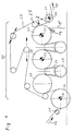
- a fibrous web 1 is coming from a web treatment device (for example a coating station or size press) via a Spreader roll 20 is fed around drying cylinder 34 to single-felt dryer group 30. Because the drying cylinder 34 is not wrapped around by the support belt 29, it has a separate drive 24. When the fibrous web 1 passes through the single-felt drying group 30 in the web running direction 15, the cylinders 33, 32 and 31 on their upper regions of the outer surface of the web 1 looped one after the other. Deflection rollers 27 with web stabilizers 26 are located between the cylinders 33, 32 and 31, which are also wrapped by the support belt 29. These deflection rollers 27 are suction rollers and can be perforated, grooved or perforated and grooved rollers. The suction rolls 27 and the pockets between the cylinders 33, 32, 31 and the suction rolls 27 are sucked in via the web stabilizer 26.
- a web treatment device for example a coating station or size press
- the support belt 29 is deflected on the guide roller 25 in such a way that the fibrous web 1 resting on the cylinder 31 is released on its upper side.
- the subsequent web guide roller 21 is optionally provided with a separate drive 24.
- a web tension in the fibrous web 1 can thus be built up exactly between the cylinder 31 and the web guide roller 21. In this area, where the fibrous web 1 still rests on the cylinder 31, it is particularly well supported.
- the water jet tip cutter S which is marked with an arrow, is advantageously arranged here.
- the fibrous web 1 When the fibrous web 1 has been threaded into the single-felt dryer group 30, it first runs downward on the cylinder 21 as the reject web 1 into the reject pulper (not shown). In order to avoid sticking to the cylinder 21, a scraper 14 is placed on the cylinder surface. The tip cutter S then separates the fibrous web into two individual strips at an edge distance of approximately 200-500 mm. Blower elements, also not shown, then make the narrower web strip - the so-called. Ribbon - directed around the web guide roller 21 to further elements of the paper machine. Through the drivable cylinder 21 and the web guide roller 21, which can also be driven, can now build up a defined train in the fibrous web 1, which stabilizes the separation process.
- the tip cutter After successful transfer of the fibrous web 1 to other elements of the paper machine, the tip cutter is moved transversely to the direction of web travel in the direction of the wider strip, so that the ribbon itself becomes wider.
- the transfer of the fibrous web 1 is complete and the tip cutter S can be switched off.
Landscapes
- Paper (AREA)
- Investigating Or Analysing Biological Materials (AREA)
- Preparation Of Compounds By Using Micro-Organisms (AREA)
Applications Claiming Priority (4)
| Application Number | Priority Date | Filing Date | Title |
|---|---|---|---|
| DE29607077U | 1996-04-19 | ||
| DE29607077U DE29607077U1 (de) | 1996-04-19 | 1996-04-19 | Ein-Filz-Trockengruppe |
| DE19650890A DE19650890A1 (de) | 1996-04-19 | 1996-12-07 | Ein-Filz-Trockengruppe |
| DE19650890 | 1996-12-07 |
Publications (2)
| Publication Number | Publication Date |
|---|---|
| EP0802278A2 true EP0802278A2 (fr) | 1997-10-22 |
| EP0802278A3 EP0802278A3 (fr) | 1998-07-01 |
Family
ID=26031974
Family Applications (1)
| Application Number | Title | Priority Date | Filing Date |
|---|---|---|---|
| EP97102661A Withdrawn EP0802278A3 (fr) | 1996-04-19 | 1997-02-19 | Groupe de séchage à feutre unique |
Country Status (4)
| Country | Link |
|---|---|
| US (1) | US5832626A (fr) |
| EP (1) | EP0802278A3 (fr) |
| CN (1) | CN1166554A (fr) |
| CA (1) | CA2202813A1 (fr) |
Cited By (1)
| Publication number | Priority date | Publication date | Assignee | Title |
|---|---|---|---|---|
| CN109293209A (zh) * | 2017-07-25 | 2019-02-01 | 株式会社西原环境 | 除湿干燥装置 |
Families Citing this family (3)
| Publication number | Priority date | Publication date | Assignee | Title |
|---|---|---|---|---|
| US6843762B2 (en) | 2000-12-18 | 2005-01-18 | Spencer Johnston Company | Spreader roll |
| US6482141B1 (en) | 2001-07-25 | 2002-11-19 | Spencer Johnston Company | Flexible end supporting arrangement for direct drive adjustable spreader rolls |
| CN107012714A (zh) * | 2017-06-05 | 2017-08-04 | 山东天和纸业有限公司 | 一种纸机烘缸装置 |
Family Cites Families (14)
| Publication number | Priority date | Publication date | Assignee | Title |
|---|---|---|---|---|
| SE305123B (fr) * | 1967-05-30 | 1968-10-14 | Svenska Flaektfabriken Ab | |
| DE3605085A1 (de) * | 1986-02-18 | 1987-08-20 | Hobema Maschf Hermann | Einrichtung zur herstellung und stapelung ein- oder mehrmals in querrichtung gefalteter bahnabschnitte aus papier, zellstoff, faservliesen o. dgl. |
| US4918836A (en) * | 1987-02-13 | 1990-04-24 | Beloit Corporation | Tail cutter apparatus and method |
| US4945655A (en) * | 1987-02-13 | 1990-08-07 | Beloit Corporation | Apparatus for cutting a tail from a web |
| FI84742C (fi) * | 1990-02-22 | 1992-01-10 | Valmet Paper Machinery Inc | Foerfarande och anordning vid skaerning av spetsdragningsbandet av en pappersbana. |
| DE4012246C1 (fr) * | 1990-04-14 | 1991-06-27 | J.M. Voith Gmbh, 7920 Heidenheim, De | |
| DE4038250C1 (fr) * | 1990-11-30 | 1992-01-30 | J.M. Voith Gmbh, 7920 Heidenheim, De | |
| DE9101248U1 (de) * | 1991-02-04 | 1991-05-23 | J.M. Voith Gmbh, 7920 Heidenheim | Trockenpartie für Papiermaschinen |
| DE9103749U1 (de) * | 1991-03-27 | 1991-06-27 | J.M. Voith Gmbh, 7920 Heidenheim | Wasserstrahl-Schneideinrichtung |
| DE9206341U1 (de) * | 1991-07-25 | 1992-08-13 | Sulzer-Escher Wyss GmbH, 7980 Ravensburg | Anordnung zum Überführen einer Papierbahn |
| DE4428745A1 (de) * | 1994-08-13 | 1996-02-15 | Voith Gmbh J M | Einrichtung zum Trocknen einer laufenden Bahn |
| US5505006A (en) * | 1994-09-08 | 1996-04-09 | J.M. Voith Gmbh | Device for drying a running web |
| DE29510637U1 (de) * | 1995-06-30 | 1995-10-19 | Voith Sulzer Papiermaschinen GmbH, 89522 Heidenheim | Ein-Filz-Trockengruppe |
| US5673495A (en) * | 1995-10-12 | 1997-10-07 | Voith Sulzer Papiermaschinen Gmbh | Single-tier drying section with top-felted serpentine dryer section at dry end thereof |
-
1997
- 1997-02-19 EP EP97102661A patent/EP0802278A3/fr not_active Withdrawn
- 1997-04-15 US US08/843,344 patent/US5832626A/en not_active Expired - Fee Related
- 1997-04-16 CA CA002202813A patent/CA2202813A1/fr not_active Abandoned
- 1997-04-18 CN CN97109551.5A patent/CN1166554A/zh active Pending
Cited By (2)
| Publication number | Priority date | Publication date | Assignee | Title |
|---|---|---|---|---|
| CN109293209A (zh) * | 2017-07-25 | 2019-02-01 | 株式会社西原环境 | 除湿干燥装置 |
| CN109293209B (zh) * | 2017-07-25 | 2021-05-07 | 株式会社西原环境 | 除湿干燥装置 |
Also Published As
| Publication number | Publication date |
|---|---|
| EP0802278A3 (fr) | 1998-07-01 |
| CA2202813A1 (fr) | 1997-10-19 |
| CN1166554A (zh) | 1997-12-03 |
| US5832626A (en) | 1998-11-10 |
Similar Documents
| Publication | Publication Date | Title |
|---|---|---|
| EP0509199B2 (fr) | Section de presse pour une machine à papier | |
| DE68924917T2 (de) | Einreihige trockner-vorrichtung und verfahren zum trocknen eines bandförmigen materials. | |
| AT508470B1 (de) | Verfahren und vorrichtung zum übertragen einer faserbahn von einem stützgewebe zu einem anderen | |
| DE2829209A1 (de) | Verfahren zur ueberfuehrung einer bahn von der presspartie zur trockenpartie einer papiermaschine | |
| DE3344217C2 (fr) | ||
| DE2538846B2 (de) | Einrichtung zum Überführen der Papierbahn vom Pressenteil zum Trocknungsteil einer Papiermaschine | |
| EP2217759B1 (fr) | Dispositif pour transférer une bande de papier d'une bande de soutien a une autre | |
| DE60106101T2 (de) | Überführen einer Aufführspitze einer Papierbahn | |
| DE69304469T2 (de) | Papiermaschine mit einem Einfädelsystem in der Presspartie | |
| DE10140800A1 (de) | Vorrichtung zur Behandlung einer Faserstoffbahn | |
| DE4328555A1 (de) | Trockenpartie | |
| DE4222034A1 (de) | Trennung des Randstreifens einer Papierbahn in der Pressenpartie vom wasserundurchlässigen Band | |
| EP0802278A2 (fr) | Groupe de séchage à feutre unique | |
| DE4201107C2 (de) | Trockenpartie | |
| AT400856B (de) | Vorrichtung zum überführen einer faserstoffbahn | |
| DE4408713A1 (de) | Verfahren und Vorrichtung zum Führen einer Materialbahn | |
| EP1156154A2 (fr) | Dispositif pour la fabrication d' une bande de matériau | |
| DE2214279A1 (de) | Vorrichtung zur Herstellung von Faserbahnen in einer Papiermaschine | |
| EP1478806B1 (fr) | Dispositif de lissage | |
| EP0803604A1 (fr) | Presse humide | |
| AT504418B1 (de) | Verfahren und vorrichtung zum überführen der papierbahn von einem stützgewebe | |
| EP2138632B1 (fr) | Dispositif et procédé destinés au transfert d'une bande de matériau | |
| DE29510637U1 (de) | Ein-Filz-Trockengruppe | |
| DE3731541C2 (de) | Verfahren und Vorrichtung zur stabilisierten Führung einer bewegten Materialbahn | |
| DE19644110A1 (de) | Saugkasten |
Legal Events
| Date | Code | Title | Description |
|---|---|---|---|
| PUAI | Public reference made under article 153(3) epc to a published international application that has entered the european phase |
Free format text: ORIGINAL CODE: 0009012 |
|
| AK | Designated contracting states |
Kind code of ref document: A2 Designated state(s): DE FI SE |
|
| PUAL | Search report despatched |
Free format text: ORIGINAL CODE: 0009013 |
|
| AK | Designated contracting states |
Kind code of ref document: A3 Designated state(s): DE FI SE |
|
| 17P | Request for examination filed |
Effective date: 19990104 |
|
| RAP1 | Party data changed (applicant data changed or rights of an application transferred) |
Owner name: VOITH SULZER PAPIERTECHNIK PATENT GMBH |
|
| RAP1 | Party data changed (applicant data changed or rights of an application transferred) |
Owner name: VOITH PAPER PATENT GMBH |
|
| 17Q | First examination report despatched |
Effective date: 20030724 |
|
| STAA | Information on the status of an ep patent application or granted ep patent |
Free format text: STATUS: THE APPLICATION IS DEEMED TO BE WITHDRAWN |
|
| 18D | Application deemed to be withdrawn |
Effective date: 20031205 |