EP0802283A2 - Panneau de treillis - Google Patents
Panneau de treillis Download PDFInfo
- Publication number
- EP0802283A2 EP0802283A2 EP97250118A EP97250118A EP0802283A2 EP 0802283 A2 EP0802283 A2 EP 0802283A2 EP 97250118 A EP97250118 A EP 97250118A EP 97250118 A EP97250118 A EP 97250118A EP 0802283 A2 EP0802283 A2 EP 0802283A2
- Authority
- EP
- European Patent Office
- Prior art keywords
- cell
- grid plate
- walls
- cells
- edge
- Prior art date
- Legal status (The legal status is an assumption and is not a legal conclusion. Google has not performed a legal analysis and makes no representation as to the accuracy of the status listed.)
- Withdrawn
Links
- 239000002689 soil Substances 0.000 claims abstract description 15
- 244000025254 Cannabis sativa Species 0.000 claims abstract description 4
- 238000005192 partition Methods 0.000 claims description 36
- 238000003780 insertion Methods 0.000 claims description 8
- 230000037431 insertion Effects 0.000 claims description 8
- 230000002093 peripheral effect Effects 0.000 claims description 5
- 239000003351 stiffener Substances 0.000 claims description 5
- XLYOFNOQVPJJNP-UHFFFAOYSA-N water Substances O XLYOFNOQVPJJNP-UHFFFAOYSA-N 0.000 claims description 5
- 230000035515 penetration Effects 0.000 claims description 4
- 238000002347 injection Methods 0.000 claims description 3
- 239000007924 injection Substances 0.000 claims description 3
- 230000002262 irrigation Effects 0.000 claims description 3
- 238000003973 irrigation Methods 0.000 claims description 3
- 239000002991 molded plastic Substances 0.000 claims description 2
- 230000003319 supportive effect Effects 0.000 claims 1
- 210000004027 cell Anatomy 0.000 description 144
- 238000010276 construction Methods 0.000 description 10
- 210000002421 cell wall Anatomy 0.000 description 5
- 239000002131 composite material Substances 0.000 description 2
- 238000007373 indentation Methods 0.000 description 2
- 239000000463 material Substances 0.000 description 2
- 230000004048 modification Effects 0.000 description 2
- 238000012986 modification Methods 0.000 description 2
- 239000004033 plastic Substances 0.000 description 2
- 238000003860 storage Methods 0.000 description 2
- 239000000758 substrate Substances 0.000 description 2
- 230000001944 accentuation Effects 0.000 description 1
- 230000001154 acute effect Effects 0.000 description 1
- 238000005273 aeration Methods 0.000 description 1
- 230000003698 anagen phase Effects 0.000 description 1
- 230000009286 beneficial effect Effects 0.000 description 1
- 230000015572 biosynthetic process Effects 0.000 description 1
- 230000008878 coupling Effects 0.000 description 1
- 238000010168 coupling process Methods 0.000 description 1
- 238000005859 coupling reaction Methods 0.000 description 1
- 238000006073 displacement reaction Methods 0.000 description 1
- 238000009434 installation Methods 0.000 description 1
- 238000004519 manufacturing process Methods 0.000 description 1
- 239000002362 mulch Substances 0.000 description 1
- 230000001681 protective effect Effects 0.000 description 1
- 238000009423 ventilation Methods 0.000 description 1
Images


Classifications
-
- E—FIXED CONSTRUCTIONS
- E01—CONSTRUCTION OF ROADS, RAILWAYS, OR BRIDGES
- E01C—CONSTRUCTION OF, OR SURFACES FOR, ROADS, SPORTS GROUNDS, OR THE LIKE; MACHINES OR AUXILIARY TOOLS FOR CONSTRUCTION OR REPAIR
- E01C9/00—Special pavings; Pavings for special parts of roads or airfields
- E01C9/004—Pavings specially adapted for allowing vegetation
Definitions
- the invention relates to a grid plate according to the preamble of claim 1.
- US Pat. No. 3,969,375 discloses an element for the production of play areas, the cells of which have a hexagonal shape, the cells or chambers located at the edge of the element being open partial chambers which are supplemented to form complete cells when elements are placed next to one another, the cell walls of adjacent elements only touching along their vertical edges.
- EP-A-0 516 957 describes a similar grid plate, which is characterized in that at least every next but one chamber on the edge is cut and complete chambers or cells are formed from partial chambers by placing the vertical edges of side walls of individual cells of adjacent grid plates against one another. Another form of contacting or touching side walls of chambers or cells open at the edge is described in DE utility model G 94 17 815.1.
- the grid plate shown in this document for fastening natural ground with partial chambers arranged in the edge area has side walls which lie flat on one another when adjacent plates are joined, with angled shapes of various shapes, such as an L-shape or a T-shape, or an obtuse-angled kink in of the scriptures.
- DE document 44 15 595 describes a lawn grid plate made of plastic, which has circular or polygonal contact surfaces on its underside, which are essentially flat.
- the grid plates described in the cited documents have a number of disadvantages.
- the plates are either completely smooth on their underside and therefore cannot be stacked, let alone transported, to prevent them from slipping, or they have spike tips and other accentuations that get stuck in the plates below, particularly during transport, and thus also represent an obstacle to trouble-free transport.
- Another disadvantage relates to the design of the edge zones of these grid plates, which - although improved as in DE utility model G 94 17 815.1 - still do not meet all the requirements of transporting and laying grid plates for the individual area.
- the grid plates and elements described in the cited documents also have the disadvantage of an edge region which is only weakly resilient compared to the inner region of these plates. This is because a mutual locking of two adjacent grid plates only takes place via different fastening or locking devices in the base part of such plates and elements, as a result of which all lateral forces and point-like compressive forces in the edge region of plates or elements only from their edge-side contact edges and / or surfaces can be included.
- the grid plate according to the invention is used to fasten lawns, the grid plate preferably being produced as an injection molded plastic part and being laid by connecting elements with further grid plates.
- the connecting elements can be arranged either on the vertical cell partitions 1, 1 ' or on a frame bar 62 .
- floor supports 61 with a minimally designed surface on the edge, a hindrance when connecting several grid plates due to loose soil or stones is reduced or excluded.
- the support elements 16 formed by adjacent open and / or closed cells 6, 8, 18, 18 ', 28 or by cell dividing walls 1, 1' or parts of them are the mostly positive connection between adjacent grid plates.
- the interconnected grid plates according to the invention are detached from their assembly when raised.
- the prerequisite for this is the use of connecting means known per se which, after they have snapped into place against one another, do not come loose in the direction and in the opposite direction, provided that they occur in one plane. So is a pre-assembly of several grid plates and transporting and / or laying this composite of several grid plates possible.
- Various support elements 16 in the form of u-, v- and / or L-shaped bends and / or graded extensions of adjacent cell partition walls 1, 1 ' not belonging to the same grid plate correspond to one another or enclose cell partition walls 1, 1' of the adjacent grid plate.
- the design of all individual elements of the grid plate according to the invention is described below. This also applies to the design of the floor, the floor supports 61 and the frame strip 62 and the arrangement of channel-like recesses 63 in the floor supports 61 .
- the channel-like recesses 63 have, according to the invention, to perform the task of snapping the upper edges of an underlying lattice plate into place when stacking, in order to prevent lateral slipping and to ensure additional transport security.
- honeycomb cell structure according to DE-OS 44 15 595, which is characterized in that the cell partition walls 1, 1 ' bead-shaped stiffeners 2 with webs 3, 4 on these or have on the cell partition walls 1, 1 ', the webs 3, 4 are arranged as individual webs 3 reciprocally or cross-shaped as double-webs. 4
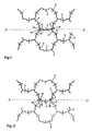
- the embodiment shown in Figure 1 is edge-side cells adjacent grid plates, the boundaries along the line A substantially - A run.
- the edge areas of adjacent grid plates consist of sub-cells 5 arranged alternately on the edge with cells 6 or 8 , the cell 6 being closed in its area bordering the cell 8 and the cell 8 being partially open and the adjoining edge areas of the cells 6 and 8 supporting elements 16 form.
- the support elements 16 consist of support walls 24 and 24 ′, as seen in horizontal section, with angled steps, with short legs 15 of the laterally open cell 8, and of angled support walls 24 of the laterally closed cell 8 .
- adjacent panels are positioned opposite each other and locked using conventional connecting elements.
- the short legs 15 of the laterally open cell 8 form-fit enclose part of the cell partition 1 of the laterally closed adjacent cell 6 .
- the sections of the support walls 24 and 24 ′ located along the edge line A - A prevent tilting about an axis of rotation parallel to the line A - A.
- the short legs 15 prevent the adjacent lattice plates from shifting laterally. Because of the relatively positive interlocking of the partial walls, pre-assembly of grids in the association from the manufacturer's factory is possible, for example, to 3 x 3 or 4 x 4 grids, without the fact that when lifting grids from transport pallets and when laying the grids, they detach from their assembly.
- Fig. 2 shows an embodiment with peripheral cells adjacent grid plates, the boundaries along the line A is also substantially - A run.
- the edge regions of the adjacent grid plates consist of sub-cells 5 arranged alternately on the edge with cells 6 or 8 , the cells 6 being closed to the region adjacent to one another and the cells 8 being open on the side, so that a cell partition 1 of a cell 8 arranged on the edge and open on the side a grid plate at its end piece 30 runs perpendicular to floor supports 61 in such a straight line that a cell partition 1 of a cell 6, which is arranged at the edge and is closed at the side, of an adjacent grid plate engages around the end piece 30 by means of slot-shaped recess 37 .
- the further configuration of the grid plate and the assembly with adjacent grid plates are provided as described for FIG. 1.
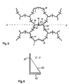
- FIG. 3 shows a modification to FIG. 2, cells 6 and cells 8 on the edge again forming support elements 16 which are designed as an extension of the cell partition construction from the cell 6 in a U-shape.
- These U-shaped configurations are slit-shaped depressions 37 arranged on the closed cell 6 via the vertical extension of the cell wall construction in the area of contact with the open cell 8 .
- In these slot-shaped depressions 37 engage the end pieces 30 of open cells 8 when joining adjacent grid plates.
- the vertical extension of the slot-shaped depressions 37 can also be limited to the upper, lower or middle vertical extension region of the edge-side cell wall construction of the closed cell 6 .
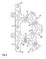
- FIG. 4 shows a further variant according to the preceding ones.
- the cell dividing wall, together with bead-like stiffening 2 with double web 4 has been omitted.
- This is in order to obtain a double-sized cell construction in the edge area of adjacent grid plates.
- Such a cell construction is provided for driving in, for example, pegs 14 or road markings, boundaries and / or parts of soil irrigation systems.
- the frame strips 62 present at right angles to the cell dividing walls 1, 1 ' in the edge region of adjacent grid plates - not shown in FIG. 4 - are interrupted. The pre-assembly, transport and laying of the grid panels are carried out as described above.
- edge-side cells 28 along an imaginary border line A - A arranged with their cell partition wall 1 or cell partition wall 1 'so that in each case the adjacent cell 28 closes off the remaining open portion of an opposing adjacent cell 28.
- the cell dividing walls 1 and 1 ' with long legs 20, 20' and short legs 15, 15 ' arranged at an angle thereon are folded axially symmetrically with respect to one another in the assembled state and are arranged to support one another.
- the short legs 15, 15 ' which touch and support each other in this way form a support element 16 in combination with the long legs 20, 20' and the end pieces 30 of the cell 28 which are located opposite each other and which are supported on them.
- This support element 16 prevents horizontal displacement of adjacent plates against each other as well as a tilting of adjacent plates to each other about an axis of rotation along the imaginary line A - A.
- FIG. 6 shows a detail of an edge region of the grid plate according to the invention in a top view of the underside, the basic cell structure being arranged offset by 30 ° compared to the previous exemplary embodiments.
- a floor consisting of floor supports 61 and frame strips 62 arranged on the edge of the plate, has channel-like recesses 63 on its side facing away from the cell dividing walls, which are modeled approximately on the honeycomb structure of the cells and / or sub-cells arranged above the floor.
- the upper edges of a grid plate snap into the channel-like recesses 63 of a grid plate above.
- the vertical extension outside the channel-like recesses 63 is approximately twice the material thickness of the cell dividing walls, while the depth of the channel-like recesses 63 corresponds to approximately half the vertical extension of the floor supports 61 or the frame strips 62 .
- the minimum width of the channel-like recesses 63 is selected so that it corresponds to twice the thickness of the cell partition walls.
- the base of the channel-like recesses 63 is flat.
- 3 x 3 or 4 x 4 grid plates are placed on top of one another on conventional pallets, so that the top edges of the plates below latch into the channel-like recesses 63 of plates above.
- 6 shows the area 65 outside the channel-like recesses 63 and double webs 64 .
- angle brackets 66 are shown, which in the edge region of cells for stiffening support walls 24 ' , end pieces 30' , u-, v- or slot-shaped depressions 37, cell partition walls 1, 1 ' and long legs 20, 20' are arranged.
- the angle supports 66 arranged approximately at right angles to the wall parts supporting them extend up to the frame strips 62 and thus give the wall parts of the cells arranged on the edge of particular stability.
- a corner edge piece of a grid plate is shown in plan view.
- the open cells 8 have, at their angled end pieces 30 ' , angular supports 66 which engage in the angled portion.
- Fig. 8 shows that these angle supports 66 do not quite reach the height of the wall parts, in this case the angled end piece 30 ' , and are saddled vertically in the bottom area on the frame bar 62 .
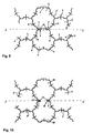
- the embodiment shown in Figure 9 shows edge-side cells adjacent grid plates, the boundaries along the line A substantially - A run.
- the edge areas of adjacent grid plates consist of sub-cells 5 arranged alternately with cells 6 or 8 , the cell 6 being closed in its area bordering the cell 8 and the cell 8 being partially open and the adjoining edge areas of the cells 6 and 8 closure elements 7 form.
- the closure elements 7 consist of V-shaped insertion slots 10 on the cell partition 1 or the bead-shaped stiffening 2 of the closed cell 6, as seen in horizontal section, and of partial walls 9 of the open cell 8 .
- adjacent panels are offset in height at the edges with their partial walls 9 positioned above the v-shaped, chamfered insertion slots 10 and at the same time all partial walls 9 of all open cells 8 of a grid plate are inserted into the v-shaped insertion slots 10 of the adjacent grid plate.
- a mounting in which the V-shaped insertion slots 10 of the adjacent grid plate to be pushed to the Operawandungen 9 is also possible, as in the immediate edge region along the line A - A no soil conditions and other connecting means are present.
- Arranged floor supports 39 are expediently provided only up to intersection points.
- Fig. 10 shows an embodiment with peripheral cells adjacent grid plates, the boundaries along the line A is also substantially - A run.
- the edge areas of the adjacent lattice panels consist of sub-cells 5 arranged alternately with cells 18 and 18 ' , the cells 18 and 18' are each open to the area adjacent to one another and partial walls 9 of the cell 18 ' with U-shaped bends 12 of the cell dividing walls open cell 18 form closure elements 17 .
- FIG. 11 shows an enlarged illustration of edge-side cells of adjacent grid plates with floor supports 39 running horizontally under the walls of cells .
- the floor supports 39 are arranged set back approximately to the height of intersections. This also has the advantage that the closure elements 7, 17, 27 can optionally be done by vertically inserting upper into lower and lower into upper cells (top and bottom each according to the arrangement in the figures) adjacent grids and also releasing connected Lattice panels is made possible.
- FIG. 12 shows a schematic section through a cell 76 of a grid plate according to the invention with indentations 78 in the form of tunnels or arches.
- the grid plate according to the invention consists of cells 76 which are open at the top and whose cell dividing walls 1 are spaced apart from the lower support 74 of the grid plate by bulges 78 which are open at the bottom.
- the cell partitions 1 are shouldered on the apex lines 75 of the convexities 78 .
- the course of the apex lines 75 of the tunnel-shaped concavities 73, 78 essentially corresponds to the course of the cell partition walls 1 arranged vertically above the concavities.
- the tunnel-shaped indentations 78 have 80 apertures 84 in its walls buckle. These serve for better root penetration and aeration, but also for material savings, in order not to unnecessarily make the grid plate according to the invention unnecessarily material-intensive without losing its strength.
- the vertical extension of the cell partition walls 1 is approximately two thirds to half of the total height of the grid plate. This results in a height of the convexities 73, 78 of approximately one third to half of the total height of the grid plate according to the invention.
- FIG. 12 and 13 show different variants of cell cross sections of the lawn grid plate, each with lower supports 74 arranged on the lower edge of the convexities 73, 78 .
- grating plates with lower supports 74 or, as shown in FIG. 15, without lower supports arranged on the lower edge of the convexities 73, 78 are offered. That is, it is intended, given the particular nature of the subsurface, that the lower edges or lower supports 74 of the bulge walls 80 press deeper into the subsurface.
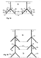
- FIG. 14 is suitable for use specifically as a grid plate for green roofing.
- the arch 73 according to the invention here contains legs 83 , which extend vertically upwards and form water chambers 82 , on the underside or lower edge of the arch walls 80 .
- FIGS. 12 to 15 The individual design variants of cell wall constructions of different types are shown in FIGS. 12 to 15, with FIGS. 12 having essentially tunnel-shaped or circular-arc-shaped cross sections of the convexities 78 , in FIGS. 14 and 15 these having a triangular shape and in FIG. 13 these have an essentially trapezoidal cross-sectional configuration.
- FIG. 15 The purpose according to the invention, namely to use the grid plate in particular as a stacking aid, is shown in FIG. 15.
- the vertical cell partition walls 1 of a grid plate are stored in the tunnel-shaped convexities 73, 78 of the next higher grid plate. Lattice panels lying one above the other can thus be stacked and transported so that they cannot slip. Since the cell partition walls 1 , which are arranged around a node, are arranged so as to engage with one another in the tunnel-shaped concavities 73, 78 of the underlying grid plate, the stacking height of several lawn grid plates is considerably reduced. At In the cell wall constructions of various lattice plates shown in FIGS. 12 to 15, the stack height is reduced by approximately one third.
- the cell partition walls 1 shouldered on the bulges 73, 78 or bulge walls 80 engage in a slip-resistant manner in the region of the apex line 75 of an overlying lattice plate.
- the dents 73, 78 do not taper at the top, but are arranged below the cell partition walls 1 in the form of penetrations of several laterally opened prismatoids with triangular, trapezoidal lateral surfaces and / or ball wedges, whereby the Taper cells 76, approximately in the shape of a truncated pyramid or a truncated cone, from the lower edge 77 of the cell dividing walls 1 .
- the aforementioned variants of cell constructions of lawn grid plates according to the invention are well suited for greening before the final laying. This is because layers of, for example, coarse mulch or planting substrates do not easily fall out of the cells 76 because of the bulges 73, 78 and lower supports 74 and fine earth can be applied to these fillings, which are then sprinkled with grass seeds and covered again with fine earth.
- the prefabricated grid panels turn green and are deeply rooted in the delicate turf. This means that they can be transported without the substrate or soil falling out of the grass pavers. Prepared or greened grid panels of this type are used where, immediately after installation, a passability is required and an overall aesthetic impression of a green area must be conveyed.
Landscapes
- Engineering & Computer Science (AREA)
- Architecture (AREA)
- Civil Engineering (AREA)
- Structural Engineering (AREA)
- Road Paving Structures (AREA)
Applications Claiming Priority (6)
| Application Number | Priority Date | Filing Date | Title |
|---|---|---|---|
| DE1996116233 DE19616233A1 (de) | 1996-04-15 | 1996-04-15 | Gitterplatte |
| DE1996116237 DE19616237A1 (de) | 1996-04-15 | 1996-04-15 | Rasengitterplatte |
| DE19616237 | 1996-04-15 | ||
| DE1996116235 DE19616235A1 (de) | 1996-04-15 | 1996-04-15 | Gitterplatte |
| DE19616233 | 1996-04-15 | ||
| DE19616235 | 1996-04-15 |
Publications (2)
| Publication Number | Publication Date |
|---|---|
| EP0802283A2 true EP0802283A2 (fr) | 1997-10-22 |
| EP0802283A3 EP0802283A3 (fr) | 1998-05-13 |
Family
ID=27216173
Family Applications (1)
| Application Number | Title | Priority Date | Filing Date |
|---|---|---|---|
| EP97250118A Withdrawn EP0802283A3 (fr) | 1996-04-15 | 1997-04-15 | Panneau de treillis |
Country Status (1)
| Country | Link |
|---|---|
| EP (1) | EP0802283A3 (fr) |
Cited By (3)
| Publication number | Priority date | Publication date | Assignee | Title |
|---|---|---|---|---|
| WO2006100705A1 (fr) * | 2005-03-23 | 2006-09-28 | Claudioforesi S.R.L. | Grille modulaire utilisee pour obtenir des chaussees carrossables sur des surfaces en herbe ou en sable |
| EP1840266A1 (fr) * | 2006-03-28 | 2007-10-03 | Sell Kunststoffen B.V. | Élément de construction en forme de plaque |
| EP2116648A1 (fr) * | 2008-05-09 | 2009-11-11 | Christian Peneder | Corps de grille pouvant recevoir des plantations destiné à recevoir des charges mobiles |
Family Cites Families (4)
| Publication number | Priority date | Publication date | Assignee | Title |
|---|---|---|---|---|
| DE9216549U1 (de) * | 1992-12-04 | 1994-04-07 | Prestele, Eugen, 86161 Augsburg | Gitterplatte |
| DE9421260U1 (de) * | 1994-02-18 | 1995-07-27 | Eberhard, Alf Hans, 78465 Konstanz | Bauelement zum Herstellen von Flächen mit sechseckigem Grundriß gleicher Seitenlänge |
| DE4415595A1 (de) * | 1994-04-28 | 1995-11-02 | Dieter Chaloun | Rasengitterplatte |
| DE9417815U1 (de) * | 1994-11-07 | 1995-01-05 | Kienle, Alexander, 86152 Augsburg | Gitterplatte zur Befestigung von natürlichem Grund |
-
1997
- 1997-04-15 EP EP97250118A patent/EP0802283A3/fr not_active Withdrawn
Cited By (3)
| Publication number | Priority date | Publication date | Assignee | Title |
|---|---|---|---|---|
| WO2006100705A1 (fr) * | 2005-03-23 | 2006-09-28 | Claudioforesi S.R.L. | Grille modulaire utilisee pour obtenir des chaussees carrossables sur des surfaces en herbe ou en sable |
| EP1840266A1 (fr) * | 2006-03-28 | 2007-10-03 | Sell Kunststoffen B.V. | Élément de construction en forme de plaque |
| EP2116648A1 (fr) * | 2008-05-09 | 2009-11-11 | Christian Peneder | Corps de grille pouvant recevoir des plantations destiné à recevoir des charges mobiles |
Also Published As
| Publication number | Publication date |
|---|---|
| EP0802283A3 (fr) | 1998-05-13 |
Similar Documents
| Publication | Publication Date | Title |
|---|---|---|
| DE2704722C2 (de) | Pflanzkasten | |
| EP0516957B1 (fr) | Panneau de treillis | |
| EP0430890B1 (fr) | Elément de paroi pour la construction à sec de murs, système constructif pour la fixation de pentes et paroi de soutènement obtenue par le système | |
| DE2731228C2 (de) | Formstein aus Beton für die Herstellung einer Stützmauer sowie aus derartigen Formsteinen hergestellte Stützmauer | |
| DE69628182T2 (de) | Zellförmige begrenzungsstruktur | |
| EP0319465A1 (fr) | Assortiment de pierres en béton pour murs pour construire un mur empilé à sec | |
| EP0455260B1 (fr) | Elément de support pour surfaces de gazon | |
| DE3320744A1 (de) | Dachziegel | |
| AT399007B (de) | Wasserspeicherplatte | |
| EP0187615B1 (fr) | Jeu d'éléments pour constructions composites | |
| EP0039448A2 (fr) | Paroi constituée par des éléments en béton | |
| DE10062711C2 (de) | Kunststoffgitterplatte zur Befestigung von Straßenbanketten | |
| EP0802283A2 (fr) | Panneau de treillis | |
| EP0024500B1 (fr) | Elément de construction en béton | |
| WO1992020864A1 (fr) | Dalle agglomeree en beton pour revetements du sol | |
| DE4415595A1 (de) | Rasengitterplatte | |
| EP0679764B1 (fr) | Panneau de treillis pour surfaces de gazon et consolidation des surfaces de gazon avec de tels panneaux | |
| DE4014935C2 (fr) | ||
| CH686296A5 (de) | Rasenschutzwabe. | |
| DE19616235A1 (de) | Gitterplatte | |
| DE29602675U1 (de) | Formstein zur Flächenbefestigung von Bodenflächen | |
| DE19640819A1 (de) | Verlegeelementanordnung für befestigte Rasenflächen | |
| DE2737322A1 (de) | Formstein, insbesondere fuer den gartenbau | |
| DE102016115212A1 (de) | Lastverteilerplatte aus Kunststoff | |
| EP0860550A2 (fr) | Dispositif de plantation d'arbres |
Legal Events
| Date | Code | Title | Description |
|---|---|---|---|
| PUAI | Public reference made under article 153(3) epc to a published international application that has entered the european phase |
Free format text: ORIGINAL CODE: 0009012 |
|
| AK | Designated contracting states |
Kind code of ref document: A2 Designated state(s): AT BE CH DK ES FR GB IE IT LI NL |
|
| PUAL | Search report despatched |
Free format text: ORIGINAL CODE: 0009013 |
|
| AK | Designated contracting states |
Kind code of ref document: A3 Designated state(s): AT BE CH DK ES FR GB IE IT LI NL |
|
| 17P | Request for examination filed |
Effective date: 19980918 |
|
| RAP3 | Party data changed (applicant data changed or rights of an application transferred) |
Owner name: HORTI-PLAST GMBH |
|
| RAP1 | Party data changed (applicant data changed or rights of an application transferred) |
Owner name: SCHWILL, HANS-DIETER |
|
| 17Q | First examination report despatched |
Effective date: 20001208 |
|
| GRAH | Despatch of communication of intention to grant a patent |
Free format text: ORIGINAL CODE: EPIDOS IGRA |
|
| STAA | Information on the status of an ep patent application or granted ep patent |
Free format text: STATUS: THE APPLICATION HAS BEEN WITHDRAWN |
|
| 18W | Application withdrawn |
Effective date: 20030405 |