EP0802296A2 - Ouvrant, tel qu'une porte, avec commande électromécanique - Google Patents
Ouvrant, tel qu'une porte, avec commande électromécanique Download PDFInfo
- Publication number
- EP0802296A2 EP0802296A2 EP97106384A EP97106384A EP0802296A2 EP 0802296 A2 EP0802296 A2 EP 0802296A2 EP 97106384 A EP97106384 A EP 97106384A EP 97106384 A EP97106384 A EP 97106384A EP 0802296 A2 EP0802296 A2 EP 0802296A2
- Authority
- EP
- European Patent Office
- Prior art keywords
- swivel
- coupling device
- wing
- door
- usual
- Prior art date
- Legal status (The legal status is an assumption and is not a legal conclusion. Google has not performed a legal analysis and makes no representation as to the accuracy of the status listed.)
- Withdrawn
Links
- 230000008878 coupling Effects 0.000 claims abstract description 25
- 238000010168 coupling process Methods 0.000 claims abstract description 25
- 238000005859 coupling reaction Methods 0.000 claims abstract description 25
- 230000005540 biological transmission Effects 0.000 claims description 8
- 239000000853 adhesive Substances 0.000 claims description 2
- 230000001070 adhesive effect Effects 0.000 claims description 2
- 210000002414 leg Anatomy 0.000 description 3
- 238000013459 approach Methods 0.000 description 1
- 210000000629 knee joint Anatomy 0.000 description 1
- 238000000034 method Methods 0.000 description 1
Images


Classifications
-
- E—FIXED CONSTRUCTIONS
- E05—LOCKS; KEYS; WINDOW OR DOOR FITTINGS; SAFES
- E05F—DEVICES FOR MOVING WINGS INTO OPEN OR CLOSED POSITION; CHECKS FOR WINGS; WING FITTINGS NOT OTHERWISE PROVIDED FOR, CONCERNED WITH THE FUNCTIONING OF THE WING
- E05F3/00—Closers or openers with braking devices, e.g. checks; Construction of pneumatic or liquid braking devices
- E05F3/22—Additional arrangements for closers, e.g. for holding the wing in opened or other position
-
- E—FIXED CONSTRUCTIONS
- E05—LOCKS; KEYS; WINDOW OR DOOR FITTINGS; SAFES
- E05F—DEVICES FOR MOVING WINGS INTO OPEN OR CLOSED POSITION; CHECKS FOR WINGS; WING FITTINGS NOT OTHERWISE PROVIDED FOR, CONCERNED WITH THE FUNCTIONING OF THE WING
- E05F15/00—Power-operated mechanisms for wings
- E05F15/70—Power-operated mechanisms for wings with automatic actuation
- E05F15/72—Power-operated mechanisms for wings with automatic actuation responsive to emergency conditions, e.g. fire
-
- E—FIXED CONSTRUCTIONS
- E05—LOCKS; KEYS; WINDOW OR DOOR FITTINGS; SAFES
- E05F—DEVICES FOR MOVING WINGS INTO OPEN OR CLOSED POSITION; CHECKS FOR WINGS; WING FITTINGS NOT OTHERWISE PROVIDED FOR, CONCERNED WITH THE FUNCTIONING OF THE WING
- E05F3/00—Closers or openers with braking devices, e.g. checks; Construction of pneumatic or liquid braking devices
- E05F3/22—Additional arrangements for closers, e.g. for holding the wing in opened or other position
- E05F2003/228—Arrangements where the end of the closer arm is sliding in a track
-
- E—FIXED CONSTRUCTIONS
- E05—LOCKS; KEYS; WINDOW OR DOOR FITTINGS; SAFES
- E05F—DEVICES FOR MOVING WINGS INTO OPEN OR CLOSED POSITION; CHECKS FOR WINGS; WING FITTINGS NOT OTHERWISE PROVIDED FOR, CONCERNED WITH THE FUNCTIONING OF THE WING
- E05F3/00—Closers or openers with braking devices, e.g. checks; Construction of pneumatic or liquid braking devices
- E05F3/22—Additional arrangements for closers, e.g. for holding the wing in opened or other position
- E05F3/227—Additional arrangements for closers, e.g. for holding the wing in opened or other position mounted at the top of wings, e.g. details related to closer housings, covers, end caps or rails therefor
-
- E—FIXED CONSTRUCTIONS
- E05—LOCKS; KEYS; WINDOW OR DOOR FITTINGS; SAFES
- E05Y—INDEXING SCHEME ASSOCIATED WITH SUBCLASSES E05D AND E05F, RELATING TO CONSTRUCTION ELEMENTS, ELECTRIC CONTROL, POWER SUPPLY, POWER SIGNAL OR TRANSMISSION, USER INTERFACES, MOUNTING OR COUPLING, DETAILS, ACCESSORIES, AUXILIARY OPERATIONS NOT OTHERWISE PROVIDED FOR, APPLICATION THEREOF
- E05Y2900/00—Application of doors, windows, wings or fittings thereof
- E05Y2900/10—Application of doors, windows, wings or fittings thereof for buildings or parts thereof
- E05Y2900/13—Type of wing
- E05Y2900/132—Doors
Definitions
- the invention relates to pivoting wings such as doors and the like with an electromechanical rotary wing drive according to the preamble of claim 1.
- the free end of the one-piece lever usually has a pin which is rotatably connected to a slide or slider which can be moved in a rail which is generally attached to the upper edge of a door to be opened or closed.
- a pin which is rotatably connected to a slide or slider which can be moved in a rail which is generally attached to the upper edge of a door to be opened or closed.
- the object of the present invention is to provide a simple possibility for emergency situations in order to open up an escape possibility for people.
- a releasable coupling device is provided for this. This is realized between the output shaft of the motor-gear unit and the rail that can be attached to the swivel wing.
- the releasable coupling direction can now be brought into its release position when the triggering forces are exceeded.
- the coupling device is preferably designed as a non-positive connection device, which releases its connection when the triggering forces are exceeded, so that the door can be mechanically pivoted in the direction of escape opposite to its usual opening direction.
- the door is preferably simply pivoted back into its closed position, so that the coupling device, which is preferably designed as a snap or clamp connection, is brought back into the usual drive connection position.
- the releasable coupling device as a clamping, latching, adhesive or snap device or in the form of a permanent magnetic or electromagnetic coupling device.
- the releasable coupling device comprises two parts, namely a pin or a pin arrangement, and second a snap or clip device which at least partially overlaps the pin or the pin arrangement.
- the pin is preferably attached to the free end of the transmission lever and the clamping device on the slider, which can be moved in the rail attached to the door.
- a pivoting wing in the form of a door 1 is shown in a schematic perspective view, which can be pivoted in the direction A from its closed position in the plane of the wall 3 in the usual opening position.
- This swivel wing i.e.
- the door 1 is designed as a swing door or swing door leaf and, in an emergency or escape, can also be opposite to the usual opening direction A, i.e. be pivoted outward in the opposite direction B.
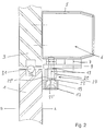
- FIGS. 2 and 3 The further structure of the rotary vane drive can be seen from FIGS. 2 and 3.
- the drive device comprises a housing 5 fastened to the wall 3 above the door leaf 1, in which a conventional electromechanical rotary leaf drive 6 with an electric motor, gear, possibly including an angular gear, is accommodated, as is basically known, for example, from DE 41 00 335 C2.
- a rail 17 is mounted, which is C-shaped in cross section according to FIG. 2 and whose opening direction points upwards.
- a slide 19 is guided in this rail 17 so as to be longitudinally displaceable.
- an angle 23 covering the rail 17 at least in the leg region on the door side is provided on the upper side of the slider, with a horizontal leg 23 'sitting on the slider 19 and fastened above it and a rear vertical leg 23' 'running parallel to the door leaf plane, on which a bracket 25 is attached, which is also C-shaped in plan view, and which overlaps the connecting pin 13 in the usual connecting position at least partially without play.
- a detachable coupling device 27 which acts in a non-positive manner, is created by the connecting pin 13 and the clip also referred to below as the connecting clip 25.
- a sensor if, for example, a person approaches the door triggers the electro-mechanical rotating-wing drive unit 6 housed in the housing 5 and, in addition, rotates the output shaft 7 such that the transmission lever 9 is above it from the wall 3 is turned away. Due to the rotary connection from the transmission lever 9, via the connecting pin 13, the connecting clip 25 comprising the connecting pin 13 and the slider 17, the associated door leaf 1 is pivoted into the open position A and, when the electromechanical rotary leaf drive unit is actuated in the opposite direction, is returned to the usual closed position.
- the releasable coupling device 27 would then be released. In other words, widening the clamp 25, the connecting clamp 25 would be pulled off the connecting pin 13 and thus the usual rotary connection would be interrupted. The door leaf 1 can then be pivoted mechanically freely in the escape route direction B.
- FIG. shows the angle 23, which is seated on the slider 19 and on which the mentioned clamp 25 is facing in the normal opening direction A. From this graphic representation it can also be seen that the top view is more than semi-cylindrical Shaped bracket facing in the opening direction is provided with two bends 25 'extending away from each other. These are thus arranged in a wedge shape diverging in the opening direction.
- connection pin 13 is reinserted into the connection bracket 25 after disengaging in the event of a panic in a very simple manner by hand.
- the door leaf only has to be returned to its usual closed position and sufficient connecting forces are generated so that the clamp 25 can snap back onto the connecting pin 13 and partially overlap it.
- the pin 13 runs onto the diverging extensions 25 'of the clamp 25 and automatically leads to the spreading of the clamp 25 until it engages over the pin in the area of its maximum transverse dimension and can snap together again in the direction of relaxation.
- the releasable coupling device 27 is designed so that the holding force between the connecting bracket 25 and the connecting pin 13 is greater than the force exerted by the electromechanical rotary leaf drive on the door leaf 1 in the Location is.
- detachable coupling devices 27 differ from the exemplary embodiment shown non-positive coupling devices 27 possible.
- the releasable coupling device can work in a force-fitting and / or form-fitting manner.
- the interlocking connecting parts of the interlocking connection are at least partially elastic, this ensures that pivoting into the release position is made possible when the triggering forces are reached and exceeded.
- the cooperating connecting parts i. H. in the exemplary embodiment shown, the connecting pin 13 and the connecting clip 25 can also be mounted upside down, that is to say, for example, the connecting pin 13 sits on the slider 19 and the connecting clip 25 is in driving connection with the transmission lever 9.
Landscapes
- Power-Operated Mechanisms For Wings (AREA)
Applications Claiming Priority (2)
| Application Number | Priority Date | Filing Date | Title |
|---|---|---|---|
| DE1996115415 DE19615415A1 (de) | 1995-12-05 | 1996-04-18 | Elektromechanischer Drehflügelantrieb für Schwenkflügel |
| DE19615415 | 1996-04-18 |
Publications (2)
| Publication Number | Publication Date |
|---|---|
| EP0802296A2 true EP0802296A2 (fr) | 1997-10-22 |
| EP0802296A3 EP0802296A3 (fr) | 1998-05-06 |
Family
ID=7791690
Family Applications (1)
| Application Number | Title | Priority Date | Filing Date |
|---|---|---|---|
| EP97106384A Withdrawn EP0802296A3 (fr) | 1996-04-18 | 1997-04-17 | Ouvrant, tel qu'une porte, avec commande électromécanique |
Country Status (1)
| Country | Link |
|---|---|
| EP (1) | EP0802296A3 (fr) |
Cited By (1)
| Publication number | Priority date | Publication date | Assignee | Title |
|---|---|---|---|---|
| WO2022048784A1 (fr) * | 2020-09-07 | 2022-03-10 | Dormakaba Deutschland Gmbh | Articulation pour actionneur de porte |
Family Cites Families (2)
| Publication number | Priority date | Publication date | Assignee | Title |
|---|---|---|---|---|
| DE7739359U1 (de) * | 1977-12-23 | 1978-06-15 | Vereinigte Baubeschlagfabriken Gretsch & Co Gmbh, 7250 Leonberg | Tuerschliessvorrichtung |
| DE9303973U1 (de) * | 1993-03-18 | 1994-07-14 | Gretsch-Unitas GmbH, 71254 Ditzingen | Türschließer |
-
1997
- 1997-04-17 EP EP97106384A patent/EP0802296A3/fr not_active Withdrawn
Cited By (5)
| Publication number | Priority date | Publication date | Assignee | Title |
|---|---|---|---|---|
| WO2022048784A1 (fr) * | 2020-09-07 | 2022-03-10 | Dormakaba Deutschland Gmbh | Articulation pour actionneur de porte |
| GB2613279A (en) * | 2020-09-07 | 2023-05-31 | Dormakaba Deutschland Gmbh | Linkage for a door actuator |
| CN116324109A (zh) * | 2020-09-07 | 2023-06-23 | 多玛凯拔德国有限公司 | 用于门操作器的连杆 |
| CN116324109B (zh) * | 2020-09-07 | 2025-08-12 | 多玛凯拔德国有限公司 | 用于门操作器的连杆 |
| US12385309B2 (en) | 2020-09-07 | 2025-08-12 | Dormakaba Deutschland Gmbh | Linkage for a door actuator |
Also Published As
| Publication number | Publication date |
|---|---|
| EP0802296A3 (fr) | 1998-05-06 |
Similar Documents
| Publication | Publication Date | Title |
|---|---|---|
| DE69909204T2 (de) | Verbessertes elektrisches Schloss für eine Kraftfahrzeugtür | |
| DE4321586C2 (de) | Motorbetriebene Schließvorrichtung | |
| DE3812313A1 (de) | Tuerschloss | |
| EP0942135B2 (fr) | Dispositif de verrouillage | |
| EP3612696A1 (fr) | Système de poignée de porte d'un véhicule automobile | |
| DE69705250T2 (de) | Kupplung zur Verbindung einer elektrischen Bedienvorrichtung mit einem Bedienelement und eine elektrischen Bedienvorrichtung | |
| DE3617321A1 (de) | Vorrichtung zum oeffnen und schliessen einer tuer eines heimelektrischen geraetes, insbesondere eines elektronischen herdes | |
| WO2008064650A2 (fr) | Serrure pour portes d'aéronefs, en particulier d'hélicoptères | |
| DE3521213A1 (de) | Fallen-panikschloss, insbesondere fuer rohrrahmentueren | |
| EP1022421A2 (fr) | Dispositif déflecteur pour panneau basculant ou oscillo-battant monté pivotant sur un cadre | |
| DE2043780B2 (de) | Innenverriegelungseinrichtung für einen Kraftfahrzeug-Türverschluß | |
| DE3604083A1 (de) | Feststellvorrichtung fuer tuerfluegel mit einem tuerschliesser | |
| DE69907356T2 (de) | Vereinfachtes Schloss für eine Kraftfahrzeugtür | |
| DE4422798C5 (de) | Fehlbedienungssicherung für Fenster, Türen oder dergleichen | |
| AT395630B (de) | Doppelfluegelige brandschutztuer | |
| DE19902579C2 (de) | Verschlußvorrichtung für den unterschlagenden Flügel zweiflügeliger setzholzloser Fenster oder Türen | |
| EP0802296A2 (fr) | Ouvrant, tel qu'une porte, avec commande électromécanique | |
| DE20119106U1 (de) | Aktiver Türstopper | |
| DE3342661C2 (fr) | ||
| EP1614844A2 (fr) | Dispositif d'articulation | |
| DE19615415A1 (de) | Elektromechanischer Drehflügelantrieb für Schwenkflügel | |
| DE3209408C2 (de) | Auflageeinrichtung für Schriftgut an einem Verkleidungsrahmen eines Schiebefensters | |
| EP3327235A1 (fr) | Dispositif d'ouverture et/ou de fermeture d'un battant | |
| DE19929818A1 (de) | Beschlag für ein Fenster oder eine Tür mit einer Spaltöffnungsstellung | |
| DE19929103B4 (de) | Verschluss für Türen, Hauben, Klappen od.dgl., insbesondere Heckverschluss eines Fahrzeugs |
Legal Events
| Date | Code | Title | Description |
|---|---|---|---|
| PUAI | Public reference made under article 153(3) epc to a published international application that has entered the european phase |
Free format text: ORIGINAL CODE: 0009012 |
|
| AK | Designated contracting states |
Kind code of ref document: A2 Designated state(s): AT BE CH DE DK ES FI FR GB IT LI NL SE |
|
| PUAL | Search report despatched |
Free format text: ORIGINAL CODE: 0009013 |
|
| AK | Designated contracting states |
Kind code of ref document: A3 Designated state(s): AT BE CH DE DK ES FI FR GB IT LI NL SE |
|
| STAA | Information on the status of an ep patent application or granted ep patent |
Free format text: STATUS: THE APPLICATION HAS BEEN WITHDRAWN |
|
| 18W | Application withdrawn |
Withdrawal date: 19980731 |
|
| RAP1 | Party data changed (applicant data changed or rights of an application transferred) |
Owner name: AGTA RECORD AG |