EP0802302A1 - Steigrohr das in der nähe von der wasseroberfläche lösbar ist - Google Patents
Steigrohr das in der nähe von der wasseroberfläche lösbar ist Download PDFInfo
- Publication number
- EP0802302A1 EP0802302A1 EP96937506A EP96937506A EP0802302A1 EP 0802302 A1 EP0802302 A1 EP 0802302A1 EP 96937506 A EP96937506 A EP 96937506A EP 96937506 A EP96937506 A EP 96937506A EP 0802302 A1 EP0802302 A1 EP 0802302A1
- Authority
- EP
- European Patent Office
- Prior art keywords
- riser
- segment
- joint
- section
- stress joint
- Prior art date
- Legal status (The legal status is an assumption and is not a legal conclusion. Google has not performed a legal analysis and makes no representation as to the accuracy of the status listed.)
- Granted
Links
Images


Classifications
-
- E—FIXED CONSTRUCTIONS
- E21—EARTH OR ROCK DRILLING; MINING
- E21B—EARTH OR ROCK DRILLING; OBTAINING OIL, GAS, WATER, SOLUBLE OR MELTABLE MATERIALS OR A SLURRY OF MINERALS FROM WELLS
- E21B17/00—Drilling rods or pipes; Flexible drill strings; Kellies; Drill collars; Sucker rods; Cables; Casings; Tubings
- E21B17/02—Couplings; joints
- E21B17/08—Casing joints
- E21B17/085—Riser connections
-
- E—FIXED CONSTRUCTIONS
- E21—EARTH OR ROCK DRILLING; MINING
- E21B—EARTH OR ROCK DRILLING; OBTAINING OIL, GAS, WATER, SOLUBLE OR MELTABLE MATERIALS OR A SLURRY OF MINERALS FROM WELLS
- E21B17/00—Drilling rods or pipes; Flexible drill strings; Kellies; Drill collars; Sucker rods; Cables; Casings; Tubings
- E21B17/01—Risers
- E21B17/012—Risers with buoyancy elements
-
- E—FIXED CONSTRUCTIONS
- E21—EARTH OR ROCK DRILLING; MINING
- E21B—EARTH OR ROCK DRILLING; OBTAINING OIL, GAS, WATER, SOLUBLE OR MELTABLE MATERIALS OR A SLURRY OF MINERALS FROM WELLS
- E21B33/00—Sealing or packing boreholes or wells
- E21B33/02—Surface sealing or packing
- E21B33/03—Well heads; Setting-up thereof
- E21B33/035—Well heads; Setting-up thereof specially adapted for underwater installations
- E21B33/038—Connectors used on well heads, e.g. for connecting blow-out preventer and riser
-
- E—FIXED CONSTRUCTIONS
- E21—EARTH OR ROCK DRILLING; MINING
- E21B—EARTH OR ROCK DRILLING; OBTAINING OIL, GAS, WATER, SOLUBLE OR MELTABLE MATERIALS OR A SLURRY OF MINERALS FROM WELLS
- E21B7/00—Special methods or apparatus for drilling
- E21B7/12—Underwater drilling
- E21B7/128—Underwater drilling from floating support with independent underwater anchored guide base
Definitions
- This invention relates to a structure of a riser which is employed for drilling of wells at an offshore location, especially, a riser which may be rapidly disconnected near water surface when subjected to a stormy weather and may be connected easily at resumption of the operation.
- riser In the drilling of wells from a vessel at an offshore location it is necessary that a riser or elongated conductor extend from the vessel to the ocean floor, being normally connected to the well head structure.
- the function of the riser is to enclose the drill string and permit circulation of the drilling mud and drilling fluids during a drilling operation.
- the riser comprises a series of pipe-like elements which are sealably joined into an elongated single conduit.
- the riser can be subjected to water currents in more than one direction. This action will induce a number of curves and stresses into the riser structure.
- the problem however can be minimized or even obviated by the use of suitable tensioning apparatus on the drilling vessel.
- Such apparatus functions to stress the riser to a predetermined degree so that the amount of physical deformation is minimized.
- the present invention provides a system wherein a drilling vessel is connected at the ocean floor by way of a disconnectable riser.
- the latter is provided with at least one remotely actuated connecting joint.
- the connecting joint is positioned in the riser structure approximately fifty to five-hundred feet (50'-500') below the water's surface in the instance of water depths in excess of about 1,000 feet.
- 50'-500' five-hundred feet
- the upper segment can be displaced with the drill vessel while the lower segment remains substantially in place buoyed with a gas filled canister.
- the upper end of the detached segment is at a sufficient depth below the water's surface to be safe from damage as the storm passes.
- a further object is to provide such a system which is capable of permitting the riser member to be rapidly disconnected under emergency conditions at a point below the water's surface so that at least part of the riser will be displaced and the remainder held uprightly in place.
- a still further object is to provide a drill riser of the type contemplated which is adapted to be disconnected at such time as the drilling vessel is removed, and is further adapted to be readily reconnected at such time as the drilling vessel returns to recommence a drilling or production operation, either manually or by remote means.
- an offshore system for drilling well bores through a well head on an ocean floor.
- the system includes a drilling vessel floatably positioned at the water's surface and an elongated riser adapted to extend from the wellhead to the drilling vessel.
- the riser comprises a lower tubular segment comprising standard riser joins with an upper end and a lower end.
- the lower segment has a means for connecting to the subsea wellhead and a means for disconnectably engaging an upper tubular segment.
- the means for disconnectably engaging the upper segment further comprises a buoyancy system for suspending the lower segment above the ocean floor.
- the upper tubular segment has standard riser joints and a means for disconnectably engaging to the lower segment and to the drilling vessel.
- a stress joint is positioned at the lower end of the lower segment.
- the stress joint is secured to a flex joint having greater flexibility than the stress joint.
- the stress joint has a main body part which is tubular, having a first section and a second section.
- the second section has a smaller cross sectional area whereby the main body has an increased flexibility at the second as compared with the first section.
- the flex joint has a tubular main body with a flexible internal elastomeric lining which fits intimately and securely around the elongated riser system.
- the system includes a means for passing a drilling string through said elongated riser to form said well bore in the ocean floor and a first blow-out prevention means connected to the wellhead.
- the buoyancy system is positioned on said lower tubular segment to externally support said lower segment whereby to maintain the latter in a substantially upright position when said lower segment has been disengaged from the riser upper segment.
- a second blow-out prevention means is connected to the lower tubular segment of the riser.
- an elongated riser adapted to extend from a subsea wellhead to a structure at the water's surface, such as a production facility.
- the riser comprises a lower tubular segment having an upper end and a lower end.
- the lower segment has a means for connecting to the subsea wellhead.
- the riser further comprises an upper tubular segment having a means for removably connecting to the lower segment and to the surface structure.
- a stress joint is positioned at the lower end of the lower segment.
- the stress joint is associated with a flex joint having greater flexibility than the stress joint.
- the stress joint has a main body part which is cylindrical.
- the main body part has a lower section and an upper section and the upper section has a smaller cross sectional area whereby the main body has an increased flexibility at the upper section as compared with the lower section.
- the flex joint has a cylindrical main body having a lining comprising a flexible internal elastomeric material.
- the upper tubular segment can be a flexible jumper attached to the means for removably connecting to the surface structure.
- the flexible jumper can be made of steel or composite materials.
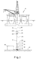
- Fig. 1 is a pictorial view of the drilling vessel and the riser.
- Fig. 2 is a cut away view of a riser segment.
- Fig. 3 is a cross-section along the lines 3-3.
- Fig. 4 is a pictorial view of a production facility using a riser.
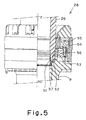
- Fig. 5 is an explanatory view of a coupling joint.
- Fig. 6 is an explanatory view of a flex joint.
- a system of the type contemplated shown in which a drilling vessel 10 is positioned at the water's surface and is adapted to drill a well bore into the floor 12 of the ocean.
- the floating vessel 10 is dynamically positioned.
- Vessel 10 supports an elongated riser member 16.
- Riser member 16 is operably connected to the drilling vessel and extends downwardly in a substantially vertical disposition to be firmly connected to the top of the well head 17 at the ocean floor 12.
- the drilling vessel 10 presently disclosed can be any one of a type normally in use as above noted for drilling offshore wells.
- the vessel shown is of the semisubmersible type, adapted for use in deep waters.
- other types of vessels, such as drill ships, or production vessels may also be used with the suggested riser system.
- Riser stabilizing systems can be used to compensate for any movement of vessel 10. The stabilizer's action will thus neutralize the condition of the riser and/or the drill string without imposing undue strain on either member.
- Submerged well head 17 is presently shown as comprising a base or foundation 18 which is fastened into the ocean floor by piles or mass anchors.
- Foundation 18 supports the necessary equipment usually carried at the ocean floor to accommodate a well drilling operation.
- Such equipment comprises primarily sufficient valving to regulate the drilling operation, together with a blowout prevention assembly 19 to facilitate the operation.
- the lower end of elongated riser 16 will firmly engage the blowout prevention 19 whereby to permit a seal therebetween to facilitate the flow of drilling fluids.
- riser 16 as shown, is fixed at its lower end to the blowout prevention 19 and at its upper end to the vessel 10.
- the blowout prevention 16 is operably fixed to a lower marine riser package 21 which is operably connected to a stress joint 23.
- Stress joint 23 is connected to standard riser joint 29 which are operably connected using a disconnectably engaging means 27 which can connect and disconnect to drilling vessel 10.
- riser 16 comprises a series of discrete, end connected tubular members 33.
- the tubular member 33 can have an outer diameter between 30 and 50 inches. Physically, the discrete members are sequentially put together on the deck of the vessel and gradually lowered to well head 17. When completed, riser 16 in effect defines an elongated continuous passage or conduit which extends between drilling vessel 10 and the well bore 11.
- the tubular member 33 comprises an inner conduit 31 shown Figure 3, and a series of pipes for carrying hydraulic fluid, drilling mud, electrical cables, fiber optic cables, choke lines, booster lines, and kill lines.
- riser 16 functions to conduct drilling mud which has been pumped from a mud pump 15 down the drill string, not shown, into the borehole 11, back up to the vessel 10. This of course is a procedure normally followed in any offshore well drilling system.
- Riser 16 when assembled is comprised of at least two elements, upper segment 26 and lower segment 9. Said segments are disconnectably engaged at a coupling joint 28 normally located 50 to 500 feet below the water's surface. Generally, joint 28 is located at a depth at which it is determined that the upper end of the lower riser segment 9 will be clear of any turbulence caused by weather conditions.
- the disconnectably engaging means 27 can disconnect or connect by remote actuating means which can bring the engaging end of the respective tubular segments into connection together.
- connectors There are a number of such pipe or conduit connectors, which are well known and used in the industry. Further, the connectors may be are usually guidably brought into engagement through the use of guide cables or the like or through the efforts of remotely operated vehicles, such as mini subs with camera apparatus.
- the actuation system operates in response to an acoustic signal originating from a vessel 10.
- An electronic signal is then transmitted upwardly to be received on the vessel 10 by suitable instrumentation whereby the vessel 10 can be displaced or adjusted to permit accurate alignment of the riser segment 26 and 9.
- riser member 16 is that it is normally so structured with hollow walls or with other means of buoyancy that it is at least partially buoyant.
- the lower segment 9 of the riser can be provided with provisional, supplementary buoyant means. The latter is actuated or properly positioned only at such time as it is required.
- the supplementary buoyancy means can comprise a series of tanks 25 fixedly positioned to the upper end of the riser 16.
- the tanks 25 are optionally communicated with the water's surface whereby buoyancy of the tank or tanks can be easily controlled through pumping in air or other inert gasses from the vessel 10.
- tanks 25 can be rigid walled members which are permanently fixed to the lower tubular segment 9 of the riser 16 upper end and fixed thereabout. Further, when this option is used, each tank is communicated with vessel 10 by a valved conduit. Although not presently shown, such conduits for underwater use are well known in the art. The conduit is further communicated with a source of air or compressed gas at the water's surface.
- the air is normally precompressed in tanks, or compressed directly in a compressor and delivered to the underwater tank 25.
- ballasting and deballasting systems and equipment have long been in use in underwater operations such as diving and the like.
- the respective tank 25 can then be ballasted as needed, or evacuated to exert a maximum upward pull on lower riser segment 9 during a disconnect operation.
- the flotation material is provided in the riser 16 structure to provide 95 % to 98 % buoyancy for the foam.
- the syntactic foam density of the buoyancy system can be changed to provide 98 % buoyancy at any water depths, compensating for changing hydrostatic pressure.
- the air canisters which provide stability for the entire riser there is 98-100 % buoyancy plus a level of tension for the entire riser system. After running the riser 16 the shipboard tensioners are applied to maintain inner tension.
- riser segment 26 When on the other hand upper riser segment 26 becomes disconnected from the lower riser segment 9 and vessel 10 is moved off location, it is first necessary to make the riser 16 buoyant by deballasting tanks 25. When rigid wall tanks are utilized, these can be similarly filled with air and pressurized to increase their buoyant capabilities.
- a first valve is located at the top of the lower riser segment 9 adjacent to the disconnection point 27.
- a remotely operated valve near the bottom of the lower riser segment 9 and communicated with the interior thereof, can be opened to allow mud to drain from the riser 16 into a retaining vessel 36, and allowing the riser 16 to equalize to the exterior water pressure.
- the drill mud can then be pumped back up to the first valve and into the riser 16 so that operations may be resumed.
- a regulating means for controlling the amount of drilling fluid which is retained in the upper and lower tubular segments 26 and 9 respectively during a disconnect of the upper and lower segments and for preventing spillage of the drilling fluid into the ocean is provided.
- a means for conveying drilling fluid away from the lower segment 9 for containerization and further regulating the flow of the drilling fluid from the tubular segments and a means for retaining 36 dispensed drilling fluid away from the riser are also provided.
- the lower segment 9 is thus provided with a valved conduit means which is communicated with and which extends from the riser lower end.
- An internal pressure monitor associated with the valved conduit means actuates the opening and closing of this valve based on the external water pressure.
- the drilling fluid or mud can then be recycled to refill the lower riser segment 9.
- the expense is readily justified if the vessel 10 and the lower segment 9 are preserved and can be readily united to continue a drilling operation.
- Use of the retaining vessel 36 will reduce the amount of drilling fluid and or drilling mud released into the ocean.
- the elongated riser 16 comprises a lower tubular segment 9 comprising standard riser joints and an upper end and a lower end.
- the lower segment 9 can be made of steel or other composite materials.
- the lower segment 9 has a means for connecting to the subsea wellhead and a means for disconnectably engaging 27 an upper tubular segment 26.
- the means for disconnectably engaging 27 the upper segment can comprise a buoyancy system for suspending the lower segment 9 above the ocean floor 12.
- the upper tubular segment 26 comprises standard riser joints and a means for disconnectably engaging; the lower segment 27 and to the drilling vessel.
- a stress joint 38 is positioned at the lower end of the lower segment 9.
- the stress joint 38 is secured to a flex joint 40 having greater flexibility than the stress joint 38.
- the means for disconnectably engaging 27 may comprise retractable wet-matable electrical fiber optic connectors that provide a telemetry path from the upper segment 26 to the lower segment 9.
- the means for disconnectably engaging can be actuated by an acoustic signal.
- the upper tubular segment 26 may also have a flex joint and a stress joint similar to those described below.
- the stress joint 38 has a main body part which is tubular and a first section and a second section.
- the second section has a smaller cross sectional area whereby the main body has an increased flexibility at the second section as compared with the first section.
- the main body of the stress joint 38 is between about 10 and about 80 feet in length.
- the second section of the stress joint 38 consists of a member of the group comprising steel, titanium, composite material and a combination of these materials, and the stress joint 38 being capable of having at least an equivalent minimum yield strength of about 45,000 psi about 120,000 psi, preferably 70,000 psi.
- the flex joint 40 has a tubular main body and a flexible internal elastomeric lining which fits intimately and securely around the elongated riser 16.
- the flex joint 40 has a rotational stiffness of between 2 kNm/degree and 200 kNm/degree.
- the flexible elastomeric lining of the flex joint 40 comprises a member of the group consisting of rubber, urethane, flouroelastomers, fluorocarbons, polysiloxanes, polyisoprene, butadiene, styrene-butadiene, acrylonitrile butadiene, polychloroprene, isobutylene-isoprene, and mixtures of rubber and composites, and mixtures thereof.
- the buoyancy system is positioned on the lower tubular segment 9 to externally support the lower segment 9 whereby to maintain the latter in a substantially upright position when the lower segment 9 has been disengaged from the upper riser segment 26.
- the buoyancy system can comprise a canister filled with a gas selected from the group of pressurized gas, air, nitrogen, and helium and mixtures thereof.
- a second blowout prevention means 42 is connected to the lower tubular segment of the riser.
- the second blowout prevention means 42 can be positioned between the buoyancy system and the wellhead and adjacent to the means for disconnectably engaging the upper segment.
- the second blowout prevention means 42 can be disposed adjacent the buoyancy system and positioned between the disconnectably engaging means 27 and the buoyancy system.
- the second blowout prevention means 42 can be disposed adjacent the buoyancy system and positioned between the buoyancy system and the well head on the ocean floor 12.
- FIG.5 An embodiment of a coupling joint 28 is illustrated in Fig.5. And an embodiment of a flex joint 40 is shown in Fig.6.
- a lower end of an upper segment 26 enters into a hole at an upper end of a lower segment 9 and is engaged to the head of the lower segment 9.
- an engaging member 53 which is externally fitted on a circumferential groove 52 at the lower end of the upper segment 26.
- the ring-like engaging member 53 is enlarged or contracted in the diameter through a taper ring 56 driven by an oil actuator composed of an oil cylinder 54 with a piston 55.
- the engaging member 53 may be disengaged or firmly engaged to the circumferential groove 52 on the lower end 51 of the upper segment 26, through enlargement or contraction in the diameter.
- a seal ring 57 also seals a clearance between the upper segment 26 and the lower segment 9.
- an upper member 61 is connected with a lower member 62 through a flex member assembly 63 and a spherical surface 64.
- the flex joint 40 allows to some extent a relative movement between the upper member 61 and the lower member 62, and absorbs the movement by deforming the flex member assembly 63.
- an elongated riser 16' adapted to extend from a subsea production of facility to a structure at the water's surface 10', such as an above sea production facility.
- the riser 16' may contain production tubing or the like disposed within the riser 16' for extracting oil and gas from the well.
- the riser 16' comprises a lower tubular segment 9' having an upper end and a lower end.
- the lower segment 9' has a means for connecting to the subsea production facility.
- the riser 16' can comprise an upper tubular segment having a means for disconnectably engaging the lower segment 9' and to the structure at the water's surface.
- the means for disconnectably engaging can have retractable wet-matable electrical fiber optic connectors that provide a telemetry path from the upper segment to the lower segment 9' and can be actuated by an acoustic signal.
- a stress joint 38' is positioned at the lower end of the lower segment 9'.
- the stress joint 38' is associated with a flex joint 40' having greater flexibility than the stress joint 38'.
- the stress joint 38' has a main body part which is cylindrical.
- the main body part has a lower section and an upper section and the upper section has a smaller cross sectional area whereby the main body has an increased flexibility at the upper section as compared with the lower section.
- the main body of the stress joint 38' is between about 10 and about 80 feet in length.
- the second section of the stress joint 38' consists of a member of the group comprising steel, titanium, composite material and a combination of these materials, and the stress joint 38' being capable of having at least a minimum yield strength of about 45,000 psi to about 120,000 psi, preferably about 70,000 psi.
- the flex joint 40' has a cylindrical main body with a lining comprising a flexible internal elastomeric material.
- the flex joint 40' has a rotational stiffness of between 2kNm/degree and 200kNm/degree.
- the flexible elastomeric lining of the flex joint 40' comprises a member of the group consisting of rubber, urethane, flouroelastomers, fluorocarbons, polysiloxanes, polyisoprene, butadiene, styrene-butadiene, acrylonitrile butadiene, polychloroprene, isobutylene-isoprene, and mixtures of rubber and composites, and mixtures thereof.
- the second end of the lower tubular segment 9 may have a flex joint and a stress joint as described previously.
- the upper tubular segment 26' can be a flexible jumper attached to the means for removably connecting to the surface structure.
- the flexible jumper can be made of steel or composite materials.
- a drilling vessel in drilling of sea bottom wells at an offshore location, may be moved quickly to a safe location when subjected to typhoons and may be early resumed the operations after typhoons are over.
- the invention contributes largely to safety, excellent workability and cost saving of the operation.
Landscapes
- Engineering & Computer Science (AREA)
- Life Sciences & Earth Sciences (AREA)
- Geology (AREA)
- Mining & Mineral Resources (AREA)
- Physics & Mathematics (AREA)
- Environmental & Geological Engineering (AREA)
- Fluid Mechanics (AREA)
- General Life Sciences & Earth Sciences (AREA)
- Geochemistry & Mineralogy (AREA)
- Mechanical Engineering (AREA)
- Earth Drilling (AREA)
Applications Claiming Priority (3)
| Application Number | Priority Date | Filing Date | Title |
|---|---|---|---|
| US556609 | 1995-11-13 | ||
| US08/556,609 US5657823A (en) | 1995-11-13 | 1995-11-13 | Near surface disconnect riser |
| PCT/JP1996/003242 WO1997018380A1 (fr) | 1995-11-13 | 1996-11-06 | Tube prolongateur destine a etre detache pres de la surface de l'eau |
Publications (3)
| Publication Number | Publication Date |
|---|---|
| EP0802302A1 true EP0802302A1 (de) | 1997-10-22 |
| EP0802302A4 EP0802302A4 (de) | 2003-01-08 |
| EP0802302B1 EP0802302B1 (de) | 2004-10-06 |
Family
ID=24222074
Family Applications (1)
| Application Number | Title | Priority Date | Filing Date |
|---|---|---|---|
| EP96937506A Expired - Lifetime EP0802302B1 (de) | 1995-11-13 | 1996-11-06 | Steigrohr das in der nähe von der wasseroberfläche lösbar ist |
Country Status (5)
| Country | Link |
|---|---|
| US (1) | US5657823A (de) |
| EP (1) | EP0802302B1 (de) |
| JP (1) | JP3843334B2 (de) |
| NO (1) | NO318103B1 (de) |
| WO (1) | WO1997018380A1 (de) |
Cited By (5)
| Publication number | Priority date | Publication date | Assignee | Title |
|---|---|---|---|---|
| WO2000049267A1 (fr) | 1999-02-19 | 2000-08-24 | Bouygues Offshore | Procede et dispositif de liaison fond-surface par conduite sous-marine installee a grande profondeur |
| FR2809136A1 (fr) | 2000-05-19 | 2001-11-23 | Saibos Construcoes Maritimas L | Installation de liaison fond-surface pour conduite sous- marine, dispositif de liaison entre un flotteur et un riser, et procede d'intervention dans ledit riser |
| EP1659257A1 (de) * | 2004-11-22 | 2006-05-24 | Anadarko Petroleum Corporation | Offshore Forschungs- und produktionssystem mit verstellbaren Auftriebskammer |
| US7458425B2 (en) | 2004-09-01 | 2008-12-02 | Anadarko Petroleum Corporation | System and method of installing and maintaining an offshore exploration and production system having an adjustable buoyancy chamber |
| US9623479B2 (en) | 2010-10-15 | 2017-04-18 | Baker Hughes Incorporated | Apparatus including metal foam and methods for using same downhole |
Families Citing this family (62)
| Publication number | Priority date | Publication date | Assignee | Title |
|---|---|---|---|---|
| US6070668A (en) * | 1996-11-08 | 2000-06-06 | Sonsub Inc. | Blowout preventer spanner joint with emergency disconnect capability |
| GB9712537D0 (en) * | 1997-06-17 | 1997-08-20 | Sedco Forex Tech Inc | Method and apparatus for drilling subsea wells |
| US6216799B1 (en) * | 1997-09-25 | 2001-04-17 | Shell Offshore Inc. | Subsea pumping system and method for deepwater drilling |
| US6273193B1 (en) * | 1997-12-16 | 2001-08-14 | Transocean Sedco Forex, Inc. | Dynamically positioned, concentric riser, drilling method and apparatus |
| US6004074A (en) * | 1998-08-11 | 1999-12-21 | Mobil Oil Corporation | Marine riser having variable buoyancy |
| US6230645B1 (en) | 1998-09-03 | 2001-05-15 | Texaco Inc. | Floating offshore structure containing apertures |
| US5983822A (en) | 1998-09-03 | 1999-11-16 | Texaco Inc. | Polygon floating offshore structure |
| US6193441B1 (en) | 1999-06-24 | 2001-02-27 | Cooper Cameron Corporation | Emergency dump apparatus for buoyancy air tanks on buoyant riser systems |
| NO994094D0 (no) * | 1999-08-24 | 1999-08-24 | Aker Riser Systems As | Stigerörsanordning |
| US6419277B1 (en) * | 1999-10-29 | 2002-07-16 | Hydril Company | Conduit section having threaded section connectors and external conduits attached thereto |
| US7040406B2 (en) * | 2003-03-06 | 2006-05-09 | Tiw Corporation | Subsea riser disconnect and method |
| US6557637B1 (en) * | 2000-05-10 | 2003-05-06 | Tiw Corporation | Subsea riser disconnect and method |
| US6763889B2 (en) * | 2000-08-14 | 2004-07-20 | Schlumberger Technology Corporation | Subsea intervention |
| US7123162B2 (en) * | 2001-04-23 | 2006-10-17 | Schlumberger Technology Corporation | Subsea communication system and technique |
| GB2391889A (en) * | 2001-04-30 | 2004-02-18 | Shell Int Research | Subsea drilling riser disconnect system and method |
| US20030177146A1 (en) * | 2002-03-18 | 2003-09-18 | International Business Machines Corporation | Method, system, and program product for migrating data from one data base management system to another data base management system |
| US20040099421A1 (en) * | 2002-11-27 | 2004-05-27 | Expro Americas, Inc. | Motion compensation system for watercraft connected to subsea conduit |
| US6848515B2 (en) * | 2003-04-24 | 2005-02-01 | Helmerich & Payne, Inc. | Modular drilling rig substructure |
| US7765749B2 (en) * | 2003-04-25 | 2010-08-03 | National Oilwell, L.P. | Fast moving drilling rig |
| US7472755B2 (en) * | 2004-06-28 | 2009-01-06 | Riggs David C | Method for inspection and repair of a flexible joint |
| US20060157235A1 (en) * | 2004-10-07 | 2006-07-20 | Oceanworks International, Inc. | Termination for segmented steel tube bundle |
| US20070044972A1 (en) * | 2005-09-01 | 2007-03-01 | Roveri Francisco E | Self-supported riser system and method of installing same |
| FR2891579B1 (fr) * | 2005-10-04 | 2007-11-23 | Inst Francais Du Petrole | Colonne montante avec conduites auxiliaires rigides. |
| FR2891577B1 (fr) * | 2005-10-04 | 2007-11-16 | Inst Francais Du Petrole | Colonne montante avec conduites auxiliares montees sur tourillons. |
| US20070079969A1 (en) * | 2005-10-06 | 2007-04-12 | Ocean Works International, Inc. | Segmented steel tube bundle termination assembly |
| US8123437B2 (en) * | 2005-10-07 | 2012-02-28 | Heerema Marine Contractors Nederland B.V. | Pipeline assembly comprising an anchoring device |
| US20070081862A1 (en) * | 2005-10-07 | 2007-04-12 | Heerema Marine Contractors Nederland B.V. | Pipeline assembly comprising an anchoring device and method for installing a pipeline assembly comprising an anchoring device |
| EP1987223B1 (de) * | 2006-02-10 | 2010-07-14 | Anadarko Petroleum Corporation | System und verfahren zum festhalten eines untergrunderkundungs- und -produktionssystems |
| US7451822B2 (en) * | 2006-05-09 | 2008-11-18 | Noble Drilling Services Inc. | Method for retrieving riser for storm evacuation |
| US20090044950A1 (en) * | 2007-08-13 | 2009-02-19 | Boudreau Paul R | Buoyancy tensioning systems for offshore marine risers and methods of use |
| CN101109269B (zh) * | 2007-09-03 | 2010-11-24 | 中国海洋石油总公司 | 一种基于近水面脱离的深水钻井装置 |
| US20090212092A1 (en) * | 2008-02-21 | 2009-08-27 | Israel Stol | Method for forming friction welded compression based tubular structures |
| CN105910633B (zh) * | 2009-05-27 | 2019-10-29 | 希里克萨有限公司 | 光学传感器及使用方法 |
| FR2946082B1 (fr) * | 2009-05-29 | 2011-05-20 | Inst Francais Du Petrole | Colonne montante avec conduites auxiliaires ajustables. |
| US8783361B2 (en) * | 2011-02-24 | 2014-07-22 | Foro Energy, Inc. | Laser assisted blowout preventer and methods of use |
| US8720584B2 (en) | 2011-02-24 | 2014-05-13 | Foro Energy, Inc. | Laser assisted system for controlling deep water drilling emergency situations |
| US9845652B2 (en) * | 2011-02-24 | 2017-12-19 | Foro Energy, Inc. | Reduced mechanical energy well control systems and methods of use |
| US8783360B2 (en) * | 2011-02-24 | 2014-07-22 | Foro Energy, Inc. | Laser assisted riser disconnect and method of use |
| FR2950650B1 (fr) * | 2009-09-28 | 2013-11-22 | Inst Francais Du Petrole | Colonne montante avec conduites auxiliaires rigides assemblees par des broches |
| US20110247827A1 (en) * | 2010-04-07 | 2011-10-13 | Gavin Humphreys | Dual Drilling Activity Drilling Ship |
| NO333849B1 (no) * | 2010-04-28 | 2013-09-30 | Statoil Petroleum As | Sikkerhetsanordning og fremgangsmåte for beskyttelse av brønnbarrieren. |
| US20110284235A1 (en) * | 2010-05-03 | 2011-11-24 | Millheim Keith K | Safety System for Deep Water Drilling Units Using a Dual Blow Out Preventer System |
| US20110284237A1 (en) * | 2010-05-20 | 2011-11-24 | Benton Ferderick Baugh | Drilling riser release method |
| DE102010051164A1 (de) * | 2010-07-13 | 2012-01-19 | Wulf Splittstoeßer | Schutzeinrichtung zum Auffangen eines in ein Gewässer entweichenden Fluids |
| US8657012B2 (en) * | 2010-11-01 | 2014-02-25 | Vetco Gray Inc. | Efficient open water riser deployment |
| US8555976B2 (en) * | 2010-11-30 | 2013-10-15 | Hydrill USA Manufacturing LLC | Emergency disconnect sequence timer display and method |
| KR20140020881A (ko) | 2011-01-28 | 2014-02-19 | 엑손모빌 업스트림 리서치 캄파니 | 극지 생산 타워를 갖는 해저 생산 시스템 |
| BR112013025746B1 (pt) * | 2011-04-07 | 2021-03-23 | Horton Wison Deepwater, Inc. | Método de desenvolvimento de campo, sistema de latão flutuante de riser superiormente tensionado offshore e método para passagem de uma pluralidade de risers superiormente tensionados entre uma primeira embarcação offshore e uma segunda embarcação offshore |
| EP2699755B1 (de) * | 2011-04-18 | 2017-06-14 | Magma Global Limited | Hybridsteigleitungssystem |
| US9334695B2 (en) * | 2011-04-18 | 2016-05-10 | Magma Global Limited | Hybrid riser system |
| US8746351B2 (en) | 2011-06-23 | 2014-06-10 | Wright's Well Control Services, Llc | Method for stabilizing oilfield equipment |
| US8657013B2 (en) * | 2011-08-19 | 2014-02-25 | Cameron International Corporation | Riser system |
| US9617810B2 (en) * | 2011-12-19 | 2017-04-11 | Nautilus Minerals Pacific Pty Ltd | Delivery method and system |
| US9879402B2 (en) | 2011-12-23 | 2018-01-30 | Nautilus Minerals Niugini Limited | Disconnectable method and system for seafloor mining |
| US8919448B2 (en) * | 2012-04-13 | 2014-12-30 | Mitchell Z. Dziekonski | Modular stress joint and methods for compensating for forces applied to a subsea riser |
| GB201212701D0 (en) * | 2012-07-17 | 2012-08-29 | Silixa Ltd | Structure monitoring |
| EP2934997A4 (de) * | 2012-12-21 | 2016-11-02 | Exxonmobil Upstream Res Co | System und verfahren zur schnellabschaltung der bohrsteigrohrs einer schwimmenden bohrplattform |
| KR101671472B1 (ko) * | 2014-09-25 | 2016-11-01 | 대우조선해양 주식회사 | 해저 머드 순환 시스템 |
| CA2977364C (en) | 2015-02-26 | 2019-02-26 | Exxonmobil Upstream Research Company | Drilling riser with distributed buoyancy |
| NO349652B1 (en) * | 2016-04-01 | 2026-03-23 | Mirade Consultants Ltd | Improved Techniques in the upstream oil and gas industry |
| GB2564117B (en) * | 2017-07-03 | 2020-12-16 | Subsea 7 Norway As | Offloading hydrocarbons from subsea fields |
| US11421486B2 (en) | 2017-07-03 | 2022-08-23 | Subsea 7 Norway As | Offloading hydrocarbons from subsea fields |
Family Cites Families (19)
| Publication number | Priority date | Publication date | Assignee | Title |
|---|---|---|---|---|
| US3554277A (en) * | 1957-08-01 | 1971-01-12 | Shell Oil Co | Underwater wells |
| US3782458A (en) * | 1971-08-04 | 1974-01-01 | Gray Tool Co | Upright, swivelable buoyed conduit for offshore system |
| US3913668A (en) * | 1973-08-22 | 1975-10-21 | Exxon Production Research Co | Marine riser assembly |
| US4046191A (en) * | 1975-07-07 | 1977-09-06 | Exxon Production Research Company | Subsea hydraulic choke |
| DE2543293C3 (de) * | 1975-09-27 | 1978-03-16 | Thyssen Industrie Ag, 4300 Essen | Unterwasser-Bohreinrichtung |
| US4081039A (en) * | 1976-10-28 | 1978-03-28 | Brown Oil Tools, Inc. | Connecting assembly and method |
| US4126183A (en) * | 1976-12-09 | 1978-11-21 | Deep Oil Technology, Inc. | Offshore well apparatus with a protected production system |
| JPS5537814Y2 (de) * | 1976-12-27 | 1980-09-04 | ||
| FR2401307A1 (fr) * | 1977-07-01 | 1979-03-23 | Petroles Cie Francaise | Colonne montante deconnectable pour puits petroliers sous-marins |
| US4234047A (en) * | 1977-10-14 | 1980-11-18 | Texaco Inc. | Disconnectable riser for deep water operation |
| US4188156A (en) * | 1978-06-01 | 1980-02-12 | Cameron Iron Works, Inc. | Riser |
| US4436451A (en) * | 1980-02-20 | 1984-03-13 | Anderson Harold E | Self-standing marine riser |
| US4367055A (en) * | 1980-12-29 | 1983-01-04 | Mobil Oil Corporation | Subsea flowline connection yoke assembly and installation method |
| CA1224715A (en) * | 1983-02-18 | 1987-07-28 | Peter R. Gibb | Apparatus and method for connecting subsea production equipment to a floating facility |
| US4616707A (en) * | 1985-04-08 | 1986-10-14 | Shell Oil Company | Riser braking clamp apparatus |
| US4646840A (en) * | 1985-05-02 | 1987-03-03 | Cameron Iron Works, Inc. | Flotation riser |
| US5046896A (en) * | 1990-05-30 | 1991-09-10 | Conoco Inc. | Inflatable buoyant near surface riser disconnect system |
| US5421676A (en) * | 1993-02-08 | 1995-06-06 | Sea Engineering Associates, Inc. | Tension leg platform and method of instalation therefor |
| US5439321A (en) * | 1993-03-11 | 1995-08-08 | Conoco Inc. | Interruptive mobile production system |
-
1995
- 1995-11-13 US US08/556,609 patent/US5657823A/en not_active Expired - Lifetime
-
1996
- 1996-11-06 WO PCT/JP1996/003242 patent/WO1997018380A1/ja not_active Ceased
- 1996-11-06 JP JP51873097A patent/JP3843334B2/ja not_active Expired - Lifetime
- 1996-11-06 EP EP96937506A patent/EP0802302B1/de not_active Expired - Lifetime
-
1997
- 1997-06-30 NO NO19973051A patent/NO318103B1/no not_active IP Right Cessation
Cited By (7)
| Publication number | Priority date | Publication date | Assignee | Title |
|---|---|---|---|---|
| WO2000049267A1 (fr) | 1999-02-19 | 2000-08-24 | Bouygues Offshore | Procede et dispositif de liaison fond-surface par conduite sous-marine installee a grande profondeur |
| FR2790054A1 (fr) * | 1999-02-19 | 2000-08-25 | Bouygues Offshore | Procede et dispositif de liaison fond-surface par conduite sous marine installee a grande profondeur |
| US6461083B1 (en) | 1999-02-19 | 2002-10-08 | Bouygues Offshore | Method and device for linking surface to the seabed for a submarine pipeline installed at great depth |
| FR2809136A1 (fr) | 2000-05-19 | 2001-11-23 | Saibos Construcoes Maritimas L | Installation de liaison fond-surface pour conduite sous- marine, dispositif de liaison entre un flotteur et un riser, et procede d'intervention dans ledit riser |
| US7458425B2 (en) | 2004-09-01 | 2008-12-02 | Anadarko Petroleum Corporation | System and method of installing and maintaining an offshore exploration and production system having an adjustable buoyancy chamber |
| EP1659257A1 (de) * | 2004-11-22 | 2006-05-24 | Anadarko Petroleum Corporation | Offshore Forschungs- und produktionssystem mit verstellbaren Auftriebskammer |
| US9623479B2 (en) | 2010-10-15 | 2017-04-18 | Baker Hughes Incorporated | Apparatus including metal foam and methods for using same downhole |
Also Published As
| Publication number | Publication date |
|---|---|
| EP0802302A4 (de) | 2003-01-08 |
| NO973051D0 (no) | 1997-06-30 |
| NO318103B1 (no) | 2005-01-31 |
| NO973051L (no) | 1997-08-06 |
| WO1997018380A1 (fr) | 1997-05-22 |
| US5657823A (en) | 1997-08-19 |
| EP0802302B1 (de) | 2004-10-06 |
| JP3843334B2 (ja) | 2006-11-08 |
Similar Documents
| Publication | Publication Date | Title |
|---|---|---|
| EP0802302B1 (de) | Steigrohr das in der nähe von der wasseroberfläche lösbar ist | |
| JPWO1997018380A1 (ja) | 水面近傍で切離すライザ | |
| US4234047A (en) | Disconnectable riser for deep water operation | |
| US4059148A (en) | Pressure-compensated dual marine riser | |
| US4210208A (en) | Subsea choke and riser pressure equalization system | |
| US4291772A (en) | Drilling fluid bypass for marine riser | |
| US4351261A (en) | Riser recoil preventer system | |
| US4176986A (en) | Subsea riser and flotation means therefor | |
| AU763799B2 (en) | A system for accessing oil wells with compliant guide and coiled tubing | |
| US6155748A (en) | Deep water riser flotation apparatus | |
| ES2305892T3 (es) | Produccion y perforacion de pozos en depresion. | |
| US4098333A (en) | Marine production riser system | |
| US6461083B1 (en) | Method and device for linking surface to the seabed for a submarine pipeline installed at great depth | |
| US4176722A (en) | Marine riser system with dual purpose lift and heave compensator mechanism | |
| US6578637B1 (en) | Method and system for storing gas for use in offshore drilling and production operations | |
| US5875848A (en) | Weight management system and method for marine drilling riser | |
| US4086971A (en) | Riser pipe inserts | |
| US4081039A (en) | Connecting assembly and method | |
| GB2194979A (en) | Multi-well hydrocarbon development system | |
| AU2006202945A1 (en) | System and method of installing and maintaining an offshore exploration and production system having an adjustable buoyancy chamber | |
| US4231436A (en) | Marine riser insert sleeves | |
| US20150354296A1 (en) | Telescopic riser joint | |
| WO1998058152A1 (en) | Method and apparatus for drilling subsea wells | |
| US5220961A (en) | Assembly comprising an extension tube and a sleeving conduit inside this tube | |
| EP1659257B1 (de) | Offshore Forschungs- und produktionssystem mit verstellbaren Auftriebskammer |
Legal Events
| Date | Code | Title | Description |
|---|---|---|---|
| PUAI | Public reference made under article 153(3) epc to a published international application that has entered the european phase |
Free format text: ORIGINAL CODE: 0009012 |
|
| 17P | Request for examination filed |
Effective date: 19970717 |
|
| AK | Designated contracting states |
Kind code of ref document: A1 Designated state(s): GB |
|
| A4 | Supplementary search report drawn up and despatched |
Effective date: 20021126 |
|
| AK | Designated contracting states |
Kind code of ref document: A4 Designated state(s): GB |
|
| RIC1 | Information provided on ipc code assigned before grant |
Free format text: 7E 21B 17/01 A, 7E 21B 17/08 B |
|
| 17Q | First examination report despatched |
Effective date: 20030709 |
|
| GRAP | Despatch of communication of intention to grant a patent |
Free format text: ORIGINAL CODE: EPIDOSNIGR1 |
|
| GRAS | Grant fee paid |
Free format text: ORIGINAL CODE: EPIDOSNIGR3 |
|
| GRAA | (expected) grant |
Free format text: ORIGINAL CODE: 0009210 |
|
| AK | Designated contracting states |
Kind code of ref document: B1 Designated state(s): GB |
|
| REG | Reference to a national code |
Ref country code: GB Ref legal event code: FG4D |
|
| REG | Reference to a national code |
Ref country code: GB Ref legal event code: 732E |
|
| PLBE | No opposition filed within time limit |
Free format text: ORIGINAL CODE: 0009261 |
|
| STAA | Information on the status of an ep patent application or granted ep patent |
Free format text: STATUS: NO OPPOSITION FILED WITHIN TIME LIMIT |
|
| 26N | No opposition filed |
Effective date: 20050707 |
|
| PGFP | Annual fee paid to national office [announced via postgrant information from national office to epo] |
Ref country code: GB Payment date: 20151125 Year of fee payment: 20 |
|
| REG | Reference to a national code |
Ref country code: GB Ref legal event code: PE20 Expiry date: 20161105 |
|
| PG25 | Lapsed in a contracting state [announced via postgrant information from national office to epo] |
Ref country code: GB Free format text: LAPSE BECAUSE OF EXPIRATION OF PROTECTION Effective date: 20161105 |