EP0802306A1 - Ventilvorrichtung für Brennkraftmaschine - Google Patents
Ventilvorrichtung für Brennkraftmaschine Download PDFInfo
- Publication number
- EP0802306A1 EP0802306A1 EP97106480A EP97106480A EP0802306A1 EP 0802306 A1 EP0802306 A1 EP 0802306A1 EP 97106480 A EP97106480 A EP 97106480A EP 97106480 A EP97106480 A EP 97106480A EP 0802306 A1 EP0802306 A1 EP 0802306A1
- Authority
- EP
- European Patent Office
- Prior art keywords
- valve
- spring
- valves
- make
- maximum
- Prior art date
- Legal status (The legal status is an assumption and is not a legal conclusion. Google has not performed a legal analysis and makes no representation as to the accuracy of the status listed.)
- Granted
Links
- 230000006835 compression Effects 0.000 claims abstract description 10
- 238000007906 compression Methods 0.000 claims abstract description 10
- 125000006850 spacer group Chemical group 0.000 claims description 4
- 238000000418 atomic force spectrum Methods 0.000 description 9
- 208000034628 Celiac artery compression syndrome Diseases 0.000 description 3
- BBWBEZAMXFGUGK-UHFFFAOYSA-N bis(dodecylsulfanyl)-methylarsane Chemical compound CCCCCCCCCCCCS[As](C)SCCCCCCCCCCCC BBWBEZAMXFGUGK-UHFFFAOYSA-N 0.000 description 3
- 238000000569 multi-angle light scattering Methods 0.000 description 3
- 238000010586 diagram Methods 0.000 description 2
- 239000000446 fuel Substances 0.000 description 2
- 230000010349 pulsation Effects 0.000 description 2
- 238000005086 pumping Methods 0.000 description 2
- 230000001133 acceleration Effects 0.000 description 1
- 238000002485 combustion reaction Methods 0.000 description 1
- 230000002542 deteriorative effect Effects 0.000 description 1
- 230000009191 jumping Effects 0.000 description 1
- 238000003754 machining Methods 0.000 description 1
- 238000000034 method Methods 0.000 description 1
- 238000012986 modification Methods 0.000 description 1
- 230000004048 modification Effects 0.000 description 1
- 238000000465 moulding Methods 0.000 description 1
Images


Classifications
-
- F—MECHANICAL ENGINEERING; LIGHTING; HEATING; WEAPONS; BLASTING
- F02—COMBUSTION ENGINES; HOT-GAS OR COMBUSTION-PRODUCT ENGINE PLANTS
- F02F—CYLINDERS, PISTONS OR CASINGS, FOR COMBUSTION ENGINES; ARRANGEMENTS OF SEALINGS IN COMBUSTION ENGINES
- F02F1/00—Cylinders; Cylinder heads
- F02F1/24—Cylinder heads
- F02F1/242—Arrangement of spark plugs or injectors
-
- F—MECHANICAL ENGINEERING; LIGHTING; HEATING; WEAPONS; BLASTING
- F01—MACHINES OR ENGINES IN GENERAL; ENGINE PLANTS IN GENERAL; STEAM ENGINES
- F01L—CYCLICALLY OPERATING VALVES FOR MACHINES OR ENGINES
- F01L1/00—Valve-gear or valve arrangements, e.g. lift-valve gear
- F01L1/26—Valve-gear or valve arrangements, e.g. lift-valve gear characterised by the provision of two or more valves operated simultaneously by same transmitting-gear; peculiar to machines or engines with more than two lift-valves per cylinder
-
- F—MECHANICAL ENGINEERING; LIGHTING; HEATING; WEAPONS; BLASTING
- F01—MACHINES OR ENGINES IN GENERAL; ENGINE PLANTS IN GENERAL; STEAM ENGINES
- F01L—CYCLICALLY OPERATING VALVES FOR MACHINES OR ENGINES
- F01L1/00—Valve-gear or valve arrangements, e.g. lift-valve gear
- F01L1/46—Component parts, details, or accessories, not provided for in preceding subgroups
- F01L1/462—Valve return spring arrangements
Definitions
- the present invention relates to a valve system for an engine.
- Japanese Unexamined Patent Publication No. 1-159417 discloses a valve system for an engine having a pair of exhaust valves, in which valve opening periods of the exhaust valves are different from each other to suppress the pulsation of the exhaust gas flow, to thereby reduce the pumping loss of the engine.
- each exhaust valve is biassed by a compression spring toward the closing direction thereof, and opens when the opening force due to the associated cam becomes larger than the spring force of the compression spring.
- the profiles of the cams are made different from each other.
- the maximum valve lift of the exhaust valve becomes larger as the valve opening period thereof becomes longer, if the profiles of the cams are defined considering the durability and reliability of the exhaust valves as in the usual manner.
- the maximum valve lifts are different from each other, if the valve opening periods are made different from each other, as in the above-mentioned valve system.
- the dynamic characteristic of each exhaust valve can be made optimum if the elements used with the exhaust valve such as the compression spring, are optimized for the respective exhaust valve.
- the elements used with the exhaust valve such as the compression spring
- the number of the elements and the costs therefor increase.
- the elements are preferably identical for every exhaust valve, considering the assembly of the valve system.
- An object of the present invention is to provide a valve system for an engine capable of ensuring a good operation of the valves, while simplifying the structure and the assembly of the valve system.
- a valve system for an engine comprising: a plurality of intake or exhaust valves adapted to be driven by cams, of which profiles are different from each other to make maximum valve lifts of the valves different from each other; and compression springs biassing the valves toward the corresponding closing directions, the springs being identical to each other; wherein an initial length of the spring is made shorter as the maximum valve lift of the valve becomes smaller, to make an initial load of the spring larger as the maximum valve lift of the valve becomes smaller.
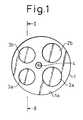
- Figs. 1 and 2 illustrate a case where the present invention is applied to a pair of exhaust valves of an engine.
- the present invention may be applied to more than two exhaust valves, a plurality of intake valves of an engine, or both the exhaust and intake valves.
- first and second intake valves 2a and 2b are arranged on one side of an inner wall 1a of a cylinder head 1 of an engine, and first and second exhaust valves 3a and 3b are arranged on the other side of the inner wall 1a of the cylinder head 1.
- the intake valves 2a and 2b are formed by the identical members, and the exhaust valves 3a and 3b also formed by the identical members.
- a spark plug 4 is arranged generally at the center of the inner wall 1a.
- the reference numerals 5 and 6 respectively designate a cylinder block and a combustion chamber of the engine
- 7a and 7b respectively designate first and second exhaust ports formed in the cylinder head 1
- 8a and 8b respectively designate first and second cams for respectively driving the first and second exhaust valves 3a and 3b.
- the cams 8a and 8b are formed on a common cam shaft 9, which rotates about an axis K-K.
- Valve lifters 10a and 10b are arranged between the tops of the exhaust valves 3a and 3b and the associated cams 8a and 8b, and slidably reciprocate within guide holes 11a and 11b formed in the cylinder head 1, while being guided by the corresponding guide holes 11a and 11b. Further, valve spring retainers 12a and 12b are connected to the tops of the exhaust valves 3a and 3b, via locks (not shown).
- Valve spring seats 13a and 13b are formed in the cylinder head 1 around the stem portions of the exhaust valves 3a and 3b, each having a recessed configuration.
- Valve springs 14a and 14b are inserted between the valve spring retainers 12a and 12b and the corresponding valve spring seats 13a and 13b, in a compressed state.
- the valve springs 14a and 14b urge the associated exhaust valves 3a and 3b toward the respective closed position of the valves 3a and 3b.
- the valve spring seat 13a for the first exhaust valve 3a is formed to make the distance H from the cam axis K-K equal to H1
- the valve spring seat 13b for the second exhaust valve 3b is formed to make the distance H from the cam axis K-K equal to H2, which is longer than H1 by DH.
- the initial length of the valve spring 14a is represented by H1-h
- that of the valve spring 14b is represented by H2-h, which is longer than that of the valve spring 14a by DH.
- valve lifters 10a and 10b, the valve spring retainer 12a and 12b, and the valve springs 14a and 14b are respectively formed by the identical members.
- the elements for the first exhaust valve 3a and those for the second exhaust valve 3b are identical. This avoids assembly errors.
- the opening forces of the cams 8a and 8b act on the associated exhaust valves 3a and 3b via the corresponding valve lifter 10a and 10b, respectively, and the exhaust valve 3a, 3b will open when the opening force acting thereon becomes larger than the closing force of the corresponding valve spring 14a, 14b.
- Fig. 3 illustrates valve lift curves of the exhaust valves 3a and 3b, the valve lift curves illustrating the relationships between the valve lift of a valve and the rotational angle of a cam.
- the curve L1 shows the valve lift curve of the first exhaust valve 3a
- the curve L2 shows the valve lift curve of the second exhaust valve 3b.
- the first exhaust valve 3a opens for a period corresponding to the cam rotational angle CA1
- the second exhaust valve 3b opens for a period corresponding to the cam rotational angle CA2.
- the valve opening period of the second exhaust valve 3b is longer than that of the first exhaust valve 3a.
- valve opening periods of the first and second exhaust valves 3a and 3b different from each other in this manner, reduces the pulsation of the exhaust gas flow and thereby the pumping loss of the engine, as mentioned at the beginning of the specification.
- the closing timings of the first and second exhaust valves 3a and 3b substantially conform to each other. This ensures the stability of the engine during the engine idling operation.
- the profiles of the cams 8a and 8b are made different from each other, as shown in Fig. 4. This simplifies the structure of the valve system. Note that the radius R of the basic circles of the cams 8a and 8b are identical to each other.
- a profile of a cam is defined to make the maximum valve lift of the associated valve as large as possible, while preventing the response of the valve from deteriorating and preventing the striking sound of the cam from being loud.
- the profiles of the cams are defined to make the valve opening periods different from each other under these limitations, the maximum valve lifts are made different from each other. Namely, as shown in Fig. 3, the maximum valve lift M1 of the first exhaust valve 3a is smaller than the maximum valve lift M2 of the second exhaust valve 3b, by DL.
- curves I1 and I2 partly illustrate the inertia of the first and second exhaust valve 3a and 3b, respectively.
- valve spring seats are formed to make the distances H identical to each other, and thus the initial lengths of the valve springs 14a and 14b are identical to each other.
- initial loads acting on the valve springs 14a and 14b are identical to each other, and thereby spring force curves of the valve springs 14a and 14b are made identical to each other.
- an initial load is a load acting on the valve spring 14a, 14b when the corresponding exhaust valve 3a, 3b is kept closed, and a spring force curve illustrates the relationships between the spring force of the valve spring 14a, 14b and the cam rotational angle.
- both the initial loads of the valve springs 14a and 14b are made equal to IL1, and thus both the spring force curves of the valve springs 14a and 14b in this case conform to the curve S1 shown in Fig. 5.
- both the valve spring seats 13a and 13b are formed to make both the initial lengths of the valve springs 14a and 14b equal to H2-h, both the initial loads are made equal to IL2, and thus both the spring force curves conform to the curve S2 shown in Fig. 5.
- the valve spring seat 13b for the exhaust valve 3b having the larger maximum valve lift is formed to make the distance H equal to H2 to make the initial lengths of the valve spring 14b equal to H2-h
- the valve spring seat 13a for the exhaust valve 3a having the smaller maximum valve lift is formed to make the distance H equal to H1, which is shorter than H2 by DH, to make the initial lengths of the valve spring 14a equal to H1-h, which is shorter than H2 by DH.
- the initial load of the valve spring 14b is made equal to IL2
- the spring force curve of the valve spring 14b conforms to the curve S2
- the initial load of the valve spring 14a is made equal to IL1, which is larger than IL2, and the spring force curve of the valve spring 14a conforms to S1. Accordingly, both the minimum excess loads of the exhaust valves 3a and 3b are made equal to the optimum value MALS.
- the initial lengths and initial loads of the valve springs 14a and 14b are adjusted by adjusting the distance H of the valve spring seats 13a and 13b, and the distance H is simply adjusted by the design of the mold for molding the cylinder head 1. Namely, the special machining and the additional elements are unnecessary, and thus the valve system is constructed at low cost and easily.
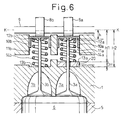
- Fig. 6 illustrates another embodiment of the present invention.
- the distance H of the valve spring seats 13a and 13b are made equal to H2.
- a spacer 20 having a thickness of DH is inserted between the bottom end of the valve spring 14b and the associated valve spring seat 13b.
- the initial lengths of the valve spring 14b is made equal to H2-h
- that of the valve spring 14a is made equal to H1-h, which is shorter than H2 by DH, as in the previous embodiment.
- Such a spacer makes the initial lengths and initial loads of the valve springs 14a and 14b adjustable in the conventional cylinder head.
- the initial length of the valve spring may be adjusted by adjusting the radius of the basic circle of the associated cam.
- valve system for an engine capable of ensuring a good operation of the valves, while simplifying the structure and the assembly of the valve system.
- a valve system for an engine comprises a plurality of intake or exhaust valves, adapted to be driven by cams of which the profiles are different from each other to make maximum valve lifts of the valves different from each other, and compression springs biassing the valves toward the corresponding closing directions, the springs being identical to each other.
- An initial length of the spring is made shorter as the maximum valve lift of the valve becomes smaller, to make an initial load of the spring larger as the maximum valve lift of the valve becomes smaller.
Landscapes
- Engineering & Computer Science (AREA)
- Mechanical Engineering (AREA)
- General Engineering & Computer Science (AREA)
- Chemical & Material Sciences (AREA)
- Combustion & Propulsion (AREA)
- Valve-Gear Or Valve Arrangements (AREA)
Applications Claiming Priority (3)
| Application Number | Priority Date | Filing Date | Title |
|---|---|---|---|
| JP9821096 | 1996-04-19 | ||
| JP09821096A JP3546278B2 (ja) | 1996-04-19 | 1996-04-19 | 内燃機関の動弁装置 |
| JP98210/96 | 1996-04-19 |
Publications (2)
| Publication Number | Publication Date |
|---|---|
| EP0802306A1 true EP0802306A1 (de) | 1997-10-22 |
| EP0802306B1 EP0802306B1 (de) | 1999-07-28 |
Family
ID=14213628
Family Applications (1)
| Application Number | Title | Priority Date | Filing Date |
|---|---|---|---|
| EP97106480A Expired - Lifetime EP0802306B1 (de) | 1996-04-19 | 1997-04-18 | Ventilvorrichtung für Brennkraftmaschine |
Country Status (4)
| Country | Link |
|---|---|
| US (1) | US5743225A (de) |
| EP (1) | EP0802306B1 (de) |
| JP (1) | JP3546278B2 (de) |
| DE (1) | DE69700353T2 (de) |
Cited By (1)
| Publication number | Priority date | Publication date | Assignee | Title |
|---|---|---|---|---|
| GB2531807A (en) * | 2014-11-03 | 2016-05-04 | Ford Global Tech Llc | Camshaft for an engine |
Families Citing this family (7)
| Publication number | Priority date | Publication date | Assignee | Title |
|---|---|---|---|---|
| JP2000120416A (ja) * | 1998-10-19 | 2000-04-25 | Toyota Motor Corp | 内燃機関の動弁装置 |
| SE517440C2 (sv) | 2000-06-20 | 2002-06-04 | Ericsson Telefon Ab L M | Elektriskt avstämbar anordning och ett förfarande relaterande därtill |
| EP2041464B1 (de) * | 2006-07-10 | 2012-07-04 | Mack Trucks, Inc. | Hin und her gehendes glied mit schwimmschutzanordnung |
| JP2009030480A (ja) * | 2007-07-25 | 2009-02-12 | Toyota Motor Corp | 筒内噴射式の内燃機関 |
| US9650924B2 (en) * | 2014-03-07 | 2017-05-16 | Electro-Motive Diesel, Inc. | Engine control system having quick-open valve timing |
| JP2023150515A (ja) * | 2022-03-31 | 2023-10-16 | ダイハツ工業株式会社 | 内燃機関の制御装置 |
| JP7764981B2 (ja) * | 2022-12-14 | 2025-11-06 | 三菱自動車工業株式会社 | 内燃機関 |
Citations (4)
| Publication number | Priority date | Publication date | Assignee | Title |
|---|---|---|---|---|
| JPS60113007A (ja) * | 1983-11-24 | 1985-06-19 | Nissan Motor Co Ltd | 内燃機関の吸・排気弁制御装置 |
| EP0319956A1 (de) * | 1987-12-08 | 1989-06-14 | Nissan Motor Co., Ltd. | Ventilsteuervorrichtung |
| EP0322572A1 (de) * | 1987-12-28 | 1989-07-05 | Yamaha Hatsudoki Kabushiki Kaisha | Ventilsteuervorrichtung für Mehrventil-Brennkraftmaschine |
| EP0453416A1 (de) * | 1990-04-20 | 1991-10-23 | FIAT AUTO S.p.A. | Brennkraftmaschine für motorisiertes Fahrzeug mit in verschiedener Weise geöffneten Ventilen |
Family Cites Families (6)
| Publication number | Priority date | Publication date | Assignee | Title |
|---|---|---|---|---|
| US4446825A (en) * | 1982-04-16 | 1984-05-08 | Ford Motor Company | Internal combustion engine with valves having a variable spring rate |
| JPH01159417A (ja) * | 1987-12-15 | 1989-06-22 | Nissan Motor Co Ltd | 内燃機関の弁装置 |
| JPH04292526A (ja) * | 1991-03-20 | 1992-10-16 | Honda Motor Co Ltd | 4サイクル内燃機関 |
| JPH07301105A (ja) * | 1994-05-06 | 1995-11-14 | Honda Motor Co Ltd | 内燃機関の動弁装置 |
| KR0164488B1 (ko) * | 1994-08-29 | 1998-12-15 | 전성원 | 외부공기를 이용한 밸브리프트 조정장치 |
| US5558054A (en) * | 1995-06-07 | 1996-09-24 | Southwest Research Institute | Variable preload system for valve springs |
-
1996
- 1996-04-19 JP JP09821096A patent/JP3546278B2/ja not_active Expired - Fee Related
-
1997
- 1997-04-10 US US08/835,596 patent/US5743225A/en not_active Expired - Lifetime
- 1997-04-18 EP EP97106480A patent/EP0802306B1/de not_active Expired - Lifetime
- 1997-04-18 DE DE69700353T patent/DE69700353T2/de not_active Expired - Fee Related
Patent Citations (4)
| Publication number | Priority date | Publication date | Assignee | Title |
|---|---|---|---|---|
| JPS60113007A (ja) * | 1983-11-24 | 1985-06-19 | Nissan Motor Co Ltd | 内燃機関の吸・排気弁制御装置 |
| EP0319956A1 (de) * | 1987-12-08 | 1989-06-14 | Nissan Motor Co., Ltd. | Ventilsteuervorrichtung |
| EP0322572A1 (de) * | 1987-12-28 | 1989-07-05 | Yamaha Hatsudoki Kabushiki Kaisha | Ventilsteuervorrichtung für Mehrventil-Brennkraftmaschine |
| EP0453416A1 (de) * | 1990-04-20 | 1991-10-23 | FIAT AUTO S.p.A. | Brennkraftmaschine für motorisiertes Fahrzeug mit in verschiedener Weise geöffneten Ventilen |
Non-Patent Citations (1)
| Title |
|---|
| PATENT ABSTRACTS OF JAPAN vol. 009, no. 268 (M - 424) 25 October 1985 (1985-10-25) * |
Cited By (2)
| Publication number | Priority date | Publication date | Assignee | Title |
|---|---|---|---|---|
| GB2531807A (en) * | 2014-11-03 | 2016-05-04 | Ford Global Tech Llc | Camshaft for an engine |
| RU2702775C2 (ru) * | 2014-11-03 | 2019-10-11 | Форд Глобал Текнолоджиз, Ллк | Двигатель, содержащий один или более распределительных валов, способ управления клапанами цилиндра двигателя и контроллер |
Also Published As
| Publication number | Publication date |
|---|---|
| EP0802306B1 (de) | 1999-07-28 |
| US5743225A (en) | 1998-04-28 |
| DE69700353D1 (de) | 1999-09-02 |
| JPH09287419A (ja) | 1997-11-04 |
| DE69700353T2 (de) | 2000-04-13 |
| JP3546278B2 (ja) | 2004-07-21 |
Similar Documents
| Publication | Publication Date | Title |
|---|---|---|
| US6332445B1 (en) | Method for operating and valve drive for a multicylinder internal combustion engine | |
| JP3700409B2 (ja) | 3次元カム用バルブリフタおよび可変動弁装置 | |
| EP0420139B1 (de) | Mehrventil-Brennkraftmaschine | |
| EP0601250A1 (de) | Hubventilsteuerungsvorrichtung für Brennkraftmaschine | |
| US5036807A (en) | Variable valve timing lift device | |
| EP0802306B1 (de) | Ventilvorrichtung für Brennkraftmaschine | |
| JPH05195736A (ja) | エンジンのバルブ駆動装置 | |
| US5988128A (en) | Valve driving apparatus for engine | |
| US7849826B2 (en) | Valve system | |
| US4911113A (en) | Valve actuating device for multiple valve type engine | |
| EP0342051B1 (de) | Ventilsteuervorrichtung für Brennkraftmaschinen | |
| US4615309A (en) | Valve actuating mechanism for internal combustion engine | |
| EP1344930B1 (de) | Brennkraftmaschine mit Kraftstoffeinspritzventil | |
| US5901675A (en) | Valve operating apparatus of DOHC | |
| US6138627A (en) | Valve operating arrangement for engine | |
| JPH0252085B2 (de) | ||
| JPH0346642B2 (de) | ||
| JP3287610B2 (ja) | 可変バルブタイミング・リフト機構 | |
| US6505593B2 (en) | Valve spring set load changing device in a valve moving apparatus of an internal combustion engine | |
| JPH06272521A (ja) | 内燃機関の動弁装置 | |
| JP7721962B2 (ja) | 内燃機関 | |
| EP0313140A1 (de) | Steuerzeitvorrichtung für Brennkraftmaschine mit hoher spezifischer Leistung | |
| JP4293078B2 (ja) | バルブ特性可変装置を備えた内燃機関 | |
| JPS62284911A (ja) | 内燃機関の吸・排気弁リフト制御装置 | |
| CA2357794A1 (en) | Attain's new spring media |
Legal Events
| Date | Code | Title | Description |
|---|---|---|---|
| PUAI | Public reference made under article 153(3) epc to a published international application that has entered the european phase |
Free format text: ORIGINAL CODE: 0009012 |
|
| 17P | Request for examination filed |
Effective date: 19970418 |
|
| AK | Designated contracting states |
Kind code of ref document: A1 Designated state(s): DE FR GB |
|
| 17Q | First examination report despatched |
Effective date: 19980403 |
|
| GRAG | Despatch of communication of intention to grant |
Free format text: ORIGINAL CODE: EPIDOS AGRA |
|
| GRAG | Despatch of communication of intention to grant |
Free format text: ORIGINAL CODE: EPIDOS AGRA |
|
| GRAH | Despatch of communication of intention to grant a patent |
Free format text: ORIGINAL CODE: EPIDOS IGRA |
|
| GRAH | Despatch of communication of intention to grant a patent |
Free format text: ORIGINAL CODE: EPIDOS IGRA |
|
| GRAA | (expected) grant |
Free format text: ORIGINAL CODE: 0009210 |
|
| AK | Designated contracting states |
Kind code of ref document: B1 Designated state(s): DE FR GB |
|
| REF | Corresponds to: |
Ref document number: 69700353 Country of ref document: DE Date of ref document: 19990902 |
|
| ET | Fr: translation filed | ||
| PLBE | No opposition filed within time limit |
Free format text: ORIGINAL CODE: 0009261 |
|
| STAA | Information on the status of an ep patent application or granted ep patent |
Free format text: STATUS: NO OPPOSITION FILED WITHIN TIME LIMIT |
|
| 26N | No opposition filed | ||
| REG | Reference to a national code |
Ref country code: GB Ref legal event code: IF02 |
|
| PGFP | Annual fee paid to national office [announced via postgrant information from national office to epo] |
Ref country code: FR Payment date: 20040408 Year of fee payment: 8 |
|
| PGFP | Annual fee paid to national office [announced via postgrant information from national office to epo] |
Ref country code: GB Payment date: 20040414 Year of fee payment: 8 |
|
| PGFP | Annual fee paid to national office [announced via postgrant information from national office to epo] |
Ref country code: DE Payment date: 20040429 Year of fee payment: 8 |
|
| PG25 | Lapsed in a contracting state [announced via postgrant information from national office to epo] |
Ref country code: GB Free format text: LAPSE BECAUSE OF NON-PAYMENT OF DUE FEES Effective date: 20050418 |
|
| PG25 | Lapsed in a contracting state [announced via postgrant information from national office to epo] |
Ref country code: DE Free format text: LAPSE BECAUSE OF NON-PAYMENT OF DUE FEES Effective date: 20051101 |
|
| GBPC | Gb: european patent ceased through non-payment of renewal fee |
Effective date: 20050418 |
|
| PG25 | Lapsed in a contracting state [announced via postgrant information from national office to epo] |
Ref country code: FR Free format text: LAPSE BECAUSE OF NON-PAYMENT OF DUE FEES Effective date: 20051230 |
|
| REG | Reference to a national code |
Ref country code: FR Ref legal event code: ST Effective date: 20051230 |