EP0802320A2 - Two stroke gasoline internal combustion engine - Google Patents
Two stroke gasoline internal combustion engine Download PDFInfo
- Publication number
- EP0802320A2 EP0802320A2 EP97400834A EP97400834A EP0802320A2 EP 0802320 A2 EP0802320 A2 EP 0802320A2 EP 97400834 A EP97400834 A EP 97400834A EP 97400834 A EP97400834 A EP 97400834A EP 0802320 A2 EP0802320 A2 EP 0802320A2
- Authority
- EP
- European Patent Office
- Prior art keywords
- piston
- stroke engine
- set forth
- duct
- crankcase chamber
- Prior art date
- Legal status (The legal status is an assumption and is not a legal conclusion. Google has not performed a legal analysis and makes no representation as to the accuracy of the status listed.)
- Withdrawn
Links
Images


Classifications
-
- F—MECHANICAL ENGINEERING; LIGHTING; HEATING; WEAPONS; BLASTING
- F02—COMBUSTION ENGINES; HOT-GAS OR COMBUSTION-PRODUCT ENGINE PLANTS
- F02B—INTERNAL-COMBUSTION PISTON ENGINES; COMBUSTION ENGINES IN GENERAL
- F02B25/00—Engines characterised by using fresh charge for scavenging cylinders
- F02B25/20—Means for reducing the mixing of charge and combustion residues or for preventing escape of fresh charge through outlet ports not provided for in, or of interest apart from, subgroups F02B25/02 - F02B25/18
-
- F—MECHANICAL ENGINEERING; LIGHTING; HEATING; WEAPONS; BLASTING
- F02—COMBUSTION ENGINES; HOT-GAS OR COMBUSTION-PRODUCT ENGINE PLANTS
- F02B—INTERNAL-COMBUSTION PISTON ENGINES; COMBUSTION ENGINES IN GENERAL
- F02B25/00—Engines characterised by using fresh charge for scavenging cylinders
- F02B25/14—Engines characterised by using fresh charge for scavenging cylinders using reverse-flow scavenging, e.g. with both outlet and inlet ports arranged near bottom of piston stroke
-
- F—MECHANICAL ENGINEERING; LIGHTING; HEATING; WEAPONS; BLASTING
- F02—COMBUSTION ENGINES; HOT-GAS OR COMBUSTION-PRODUCT ENGINE PLANTS
- F02M—SUPPLYING COMBUSTION ENGINES IN GENERAL WITH COMBUSTIBLE MIXTURES OR CONSTITUENTS THEREOF
- F02M26/00—Engine-pertinent apparatus for adding exhaust gases to combustion-air, main fuel or fuel-air mixture, e.g. by exhaust gas recirculation [EGR] systems
- F02M26/01—Internal exhaust gas recirculation, i.e. wherein the residual exhaust gases are trapped in the cylinder or pushed back from the intake or the exhaust manifold into the combustion chamber without the use of additional passages
-
- F—MECHANICAL ENGINEERING; LIGHTING; HEATING; WEAPONS; BLASTING
- F02—COMBUSTION ENGINES; HOT-GAS OR COMBUSTION-PRODUCT ENGINE PLANTS
- F02M—SUPPLYING COMBUSTION ENGINES IN GENERAL WITH COMBUSTIBLE MIXTURES OR CONSTITUENTS THEREOF
- F02M26/00—Engine-pertinent apparatus for adding exhaust gases to combustion-air, main fuel or fuel-air mixture, e.g. by exhaust gas recirculation [EGR] systems
- F02M26/13—Arrangement or layout of EGR passages, e.g. in relation to specific engine parts or for incorporation of accessories
- F02M26/37—Arrangement or layout of EGR passages, e.g. in relation to specific engine parts or for incorporation of accessories with temporary storage of recirculated exhaust gas
-
- F—MECHANICAL ENGINEERING; LIGHTING; HEATING; WEAPONS; BLASTING
- F02—COMBUSTION ENGINES; HOT-GAS OR COMBUSTION-PRODUCT ENGINE PLANTS
- F02B—INTERNAL-COMBUSTION PISTON ENGINES; COMBUSTION ENGINES IN GENERAL
- F02B75/00—Other engines
- F02B75/02—Engines characterised by their cycles, e.g. six-stroke
- F02B2075/022—Engines characterised by their cycles, e.g. six-stroke having less than six strokes per cycle
- F02B2075/025—Engines characterised by their cycles, e.g. six-stroke having less than six strokes per cycle two
Definitions
- This invention relates to a gasoline internal combustion (IC) engine, and more particularly to a two-stroke engine having reduced hydrocarbon emissions.
- IC gasoline internal combustion
- a two-stroke engine constructed in accordance with this invention comprises an engine frame forming a cylinder, and a piston mounted for reciprocating movement in the cylinder.
- the engine frame further includes a crankcase chamber and an inlet flow passage for introducing a fresh mixture into the crankcase chamber and forming a crankcase compression arrangement.
- the cylinder includes a cylinder wall having an intake port and an exhaust port.
- the piston is movable in compression and combustion strokes between a top-dead-center (TDC) position and a bottom-dead-center (BDC) position in the cylinder, and the piston includes a piston skirt.
- Movement of the piston toward the BDC position opens the intake port and the exhaust port, and fresh mixture flows from the crankcase chamber into the cylinder and scavenges the burned gases through the exhaust port.
- the inlet flow passage is opened which allows fresh mixture to flow into the crankcase chamber.
- the exhaust port is also opened, and burned gases in the exhaust port are also drawn into the crankcase chamber and combined with the fresh mixture.
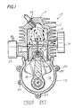
- Fig. 1 illustrates the construction and operation of a prior art two-stroke engine.
- the engine comprises an engine frame 10 that includes a block 11 and a crankcase 12. Cooling fins 13 are formed on the outside of the block 11 and a cylinder wall 14 is formed on the inside.
- a piston 16 is mounted for reciprocation in the cylinder wall 14, the cylinder wall 14 and the piston 16 forming a combustion chamber 17 between them.
- the crankcase 12 forms a crankcase chamber 18 and a crankshaft 19 is rotatably mounted in the chamber 18.
- a connecting rod 21 and a crank connect the shaft 19 to the piston 16.
- the piston 16 includes a crown 22 and a cylindrical skirt 23. Mounting ears 24 and bolts 25 are provided to secure the frame 10 to an implement to be driven.
- Flow passages are also formed in the engine frame 10 for a combustible fuel-oil-air mixture or charge and for burnt exhaust gases.
- the flow passages include an inlet flow passage or duct 31 formed radially through the block 11, and a carburetor 32 is connected to the duct 31.
- An exhaust duct 33 is also formed radially through the block 11 and connects the combustion chamber 17 with a muffler 34.
- Scavenging ducts 36 are formed longitudinally through the cylinder wall 14 and are located to connect the crankcase chamber 18 with the combustion chamber 17 when the piston 16 is adjacent the BDC position.
- the upper ends of the ducts 36 form inlet ports 37 which are open to the combustion chamber 17 when the piston 16 is in the BDC position.
- the engine operates as follows: with the piston 16 in the BDC position shown in Fig. 1, the piston skirt 23 closes the inlet duct or flow passage 31 and opens the exhaust duct 33.
- the crankcase 18 is filled with fresh mixture or charge which is compressed during the downward movement of the piston at the time when the ports 37 and the duct 31 are closed by the piston 16.
- fresh gas flows from the chamber 18, through the ducts 36 and the inlet ports 37, and into the combustion chamber 17.
- the flow of fresh gas sweeps, or scavenges, the burnt gases from the combustion chamber 17 out through the open exhaust duct 33.
- the inlet ports 37 and the duct 33 are located so that the ports 37 are closed slightly ahead of the duct 33 as the piston moves up.
- An engine operating as described above produces excessive hydrocarbon emissions, in part because, shortly before the piston 16 closes the exhaust duct 33, some of the fresh mixture flows into the exhaust duct 33 behind the burnt gases.
- the fresh mixture is retained in the duct 33 until the beginning of the next scavenging portion of the engine cycle, and then the retained fresh mixture is pushed out of the duct 33 through the muffler 34, ahead of the burnt gases in the next scavenging portion of the cycle.
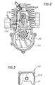
- the engine shown in Figs. 2 and 3 constructed in accordance with this invention, has a number of parts which are similar to corresponding parts shown in Fig. 1.
- the corresponding parts in Figs. 2 and 3 are given the same reference numerals plus the letter A. Only the differences in construction and operation between the engines of Figs. 1 and 2 are described in detail.
- the piston 16A (Figs. 2 and 3) has a return opening or passage 41 formed radially through the skirt 23A.
- the opening 41 is on the side of the piston which faces the exhaust duct 33A, and the opening 41 is located to be in front of the duct 33A when the piston 16A is at TDC (see Fig. 2).
- the moving piston forms a partial vacuum in the chamber 18A, as previously explained. Consequently, when the lower edge of the piston skirt 23A opens the inlet duct 31A and the opening 41 opens the exhaust duct 33A, the retained content (which includes fresh mixture and most likely some burnt gases) in the duct 33A from the previous scavenging portion of the cycle are drawn into the crankcase chamber 18A.
- the arrows 42 in Fig. 2 represent the fresh mixture from the carburetor 32A, and the arrows 43 represent the retained content from the exhaust duct 33A.
- the retained content is combined in the crankcase chamber 18A with the fresh mixture from the inlet duct 31A, and the combined gases subsequently flow through the ducts 36A when the piston 16A is next at the BDC position.
- the fresh mixture in the retained content is returned to the combustion chamber 17A and utilized rather than passed into the environment.
- any burned gases in the retained content are mixed with the fresh mixture and recirculated, thereby lowering emissions by lowering the oxides of nitrogen in the exhaust.
- the piston 16B has two return passages 46 and 47 (see especially Fig. 6) formed in it, the passages extending in the circumferential direction through the skirt 23B.
- Each of the return passages 46 and 47 has one end opening 48 which is exposed to the exhaust duct 33B and second end openings 49 which are exposed to the ducts 36B, when the piston 16B is in the TDC position.
- the retained content in the exhaust duct 33B is moved into the return passages 46 and 47 and the ducts 36B.
- the return passages are formed at least in part through the piston, and the piston functions as a valve which opens and closes the return passages as it reciprocates.
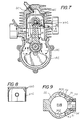
- the return passages are formed entirely in the block 11C.
- return passages 51 are formed in the block 11C.
- One end 52 of each passage 51 opens into the exhaust duct 33C and the other end 53 of each passage 51 opens into a scavenging duct 36C also formed in the block 11C.
- a one-way or check valve 54 such as a reed valve, is mounted in each return passage 51 and allows flow only in the direction from the exhaust duct 33C to the scavenging duct 36C.
- the engine of Figs. 7 to 9 functions similarly to those shown in Figs. 2 to 6.
- the valves 54 prevent fresh mixture from flowing into the exhaust duct 33C during the scavenging portion of the engine cycle.
- the inlet flow passage for the fresh mixture is formed in the cylinder wall and the inlet flow is controlled by the movement of the piston.
- the inlet flow passage for the fresh mixture may lead directly into the crankcase in all of the embodiments disclosed herein.
- the engine includes a block 11D and a crankcase 12D which forms a crankcase chamber 18D.
- a piston 16D reciprocates in a chamber 17D, the piston including a cylindrical skirt 23D.
- an inlet flow passage or duct 31D connects a carburetor (not shown in Fig. 10) to the crankcase chamber 18D.
- An intake valve 31E is mounted in the duct 31D and controls the flow of the fresh gas into the chamber 18D. While a variety of valve types, such as a reed valve or a rotary valve, may be used, a reed valve 31F is shown in Fig. 10.
- the valve 31E opens to allow the flow of fresh gas into the chamber 18D when the piston 16D moves up and forms a partial vacuum in the chamber 18D.
- the valve 31E closes when the piston moves down.
- the other parts of the engine are constructed and operate similarly to those of the embodiment shown in Figs. 2 and 3.
- valve 31E comprises a rotary valve
- the rotary valve is coupled to be rotated in timed relation with the movement of the piston. This may be accomplished by a gear coupling between the crankshaft and the rotary valve.
- the rotary valve would be configured and rotated such that the inlet flow passage is open only during the time that the piston is moving upwardly to the TDC position.
- inventions shown in Figs. 4 to 9 may have the inlet duct connected to the crankcase chamber as shown in Fig. 10 instead of to the cylinder wall as shown in Figs. 4 to 9.
- an engine in accordance with this invention has reduced exhaust emissions.
- the fresh mixture and burnt gas in the retained content of the exhaust duct are returned and recirculated into the combustion chamber rather than expelled through the muffler, thereby reducing the engine emissions into the environment.
Landscapes
- Engineering & Computer Science (AREA)
- Chemical & Material Sciences (AREA)
- Combustion & Propulsion (AREA)
- Mechanical Engineering (AREA)
- General Engineering & Computer Science (AREA)
- Cylinder Crankcases Of Internal Combustion Engines (AREA)
Abstract
This disclosure relates to a two-stroke engine comprising an engine frame forming a cylinder, and a piston mounted for reciprocating movement in the cylinder. The engine frame further includes a crankcase chamber and inlet flow passages for fresh mixture, which form a crankcase compression arrangement. The cylinder includes a cylinder wall having an intake port and an exhaust port. The piston is movable in compression and combustion strokes between a top-dead-center (TDC) position and a bottom-dead-center (BDC) position in the cylinder, and the piston includes a piston skirt. Movement of the piston toward the BDC position opens the intake port and the exhaust port, and fresh mixture flows from the crankcase chamber into the cylinder and scavenges the burned gases through the exhaust port. When the piston moves toward the TDC position, the inlet flow passage is opened which allows fresh mixture to flow into the crankcase chamber. The exhaust port is also opened, and burned gases in the exhaust port are also drawn into the crankcase chamber and combined with the fresh mixture.
Description
- This invention relates to a gasoline internal combustion (IC) engine, and more particularly to a two-stroke engine having reduced hydrocarbon emissions.
- As is well known to those skilled in this art, a two-stroke engine develops more power than a four-stroke engine of the same displacement, but the prior art two-stroke engines have the disadvantage of producing greater hydrocarbon emissions. The hydrocarbon emissions are due in part to incomplete combustion of the fuel-oil-air mixture and in part to a loss of some of the fresh mixture or charge during the scavenging part of the operating cycle. During scavenging, both the inlet port and the exhaust port are open at the same time, and the fresh mixture flows into the combustion chamber and sweeps the burned gases out through the exhaust port. Unfortunately, some of the fresh mixture also passes through the exhaust port, thereby producing the above-mentioned hydrocarbon emissions. The foregoing operation is described in more detail hereinafter in connection with Figure 1 of the drawings.
- It is a general object of the present invention to provide an improved two-stroke engine which substantially reduces the quantity of hydrocarbon emissions.
- A two-stroke engine constructed in accordance with this invention comprises an engine frame forming a cylinder, and a piston mounted for reciprocating movement in the cylinder. The engine frame further includes a crankcase chamber and an inlet flow passage for introducing a fresh mixture into the crankcase chamber and forming a crankcase compression arrangement. The cylinder includes a cylinder wall having an intake port and an exhaust port. The piston is movable in compression and combustion strokes between a top-dead-center (TDC) position and a bottom-dead-center (BDC) position in the cylinder, and the piston includes a piston skirt. Movement of the piston toward the BDC position opens the intake port and the exhaust port, and fresh mixture flows from the crankcase chamber into the cylinder and scavenges the burned gases through the exhaust port. When the piston moves toward the TDC position, the inlet flow passage is opened which allows fresh mixture to flow into the crankcase chamber. The exhaust port is also opened, and burned gases in the exhaust port are also drawn into the crankcase chamber and combined with the fresh mixture.
- The invention will be better understood from the following detailed description taken in conjunction with the accompanying figures of the drawings, wherein:
- Fig. 1 is a sectional view showing a prior art engine;
- Fig. 2 is a sectional view showing an engine constructed in accordance with this invention;
- Fig. 3 is a sectional view of a piston of the engine shown in Fig. 2;
- Figs. 4 and 5 are similar to Figs. 2 and 3 but show an alternative form of the invention;
- Fig. 6 is a sectional view taken on the line 6-6 of Fig. 4;
- Figs. 7, 8 and 9 are views similar to Figs. 4, 5 and 6 but show still another alternative form of the invention; and
- Fig. 10 is a view similar to Fig. 2 but shows still another alternative embodiment.
- Fig. 1 illustrates the construction and operation of a prior art two-stroke engine. The engine comprises an engine frame 10 that includes a block 11 and a
crankcase 12.Cooling fins 13 are formed on the outside of the block 11 and acylinder wall 14 is formed on the inside. Apiston 16 is mounted for reciprocation in thecylinder wall 14, thecylinder wall 14 and thepiston 16 forming a combustion chamber 17 between them. Thecrankcase 12 forms acrankcase chamber 18 and acrankshaft 19 is rotatably mounted in thechamber 18. A connectingrod 21 and a crank connect theshaft 19 to thepiston 16. Thepiston 16 includes a crown 22 and a cylindrical skirt 23.Mounting ears 24 andbolts 25 are provided to secure the frame 10 to an implement to be driven. - Flow passages are also formed in the engine frame 10 for a combustible fuel-oil-air mixture or charge and for burnt exhaust gases. The flow passages include an inlet flow passage or
duct 31 formed radially through the block 11, and acarburetor 32 is connected to theduct 31. Anexhaust duct 33 is also formed radially through the block 11 and connects the combustion chamber 17 with amuffler 34.Scavenging ducts 36 are formed longitudinally through thecylinder wall 14 and are located to connect thecrankcase chamber 18 with the combustion chamber 17 when thepiston 16 is adjacent the BDC position. The upper ends of theducts 36form inlet ports 37 which are open to the combustion chamber 17 when thepiston 16 is in the BDC position. - The engine operates as follows: with the
piston 16 in the BDC position shown in Fig. 1, the piston skirt 23 closes the inlet duct orflow passage 31 and opens theexhaust duct 33. Thecrankcase 18 is filled with fresh mixture or charge which is compressed during the downward movement of the piston at the time when theports 37 and theduct 31 are closed by thepiston 16. When the piston moves down to the level where theports 37 are open, fresh gas flows from thechamber 18, through theducts 36 and theinlet ports 37, and into the combustion chamber 17. The flow of fresh gas sweeps, or scavenges, the burnt gases from the combustion chamber 17 out through theopen exhaust duct 33. As thepiston 16 moves up in the compression stroke, most of the burnt gases are removed and the chamber 17 is filled with fresh mixture. Note that theinlet ports 37 and theduct 33 are located so that theports 37 are closed slightly ahead of theduct 33 as the piston moves up. - As the
piston 16 rises, it opens the inlet duct 31 (see Fig. 2) and fresh mixture is drawn into thecrankcase chamber 18 due to the partial vacuum created by the rising piston. At near TDC, a spark plug 38 fires and the piston is forced down in the power stroke. - An engine operating as described above produces excessive hydrocarbon emissions, in part because, shortly before the
piston 16 closes theexhaust duct 33, some of the fresh mixture flows into theexhaust duct 33 behind the burnt gases. The fresh mixture is retained in theduct 33 until the beginning of the next scavenging portion of the engine cycle, and then the retained fresh mixture is pushed out of theduct 33 through themuffler 34, ahead of the burnt gases in the next scavenging portion of the cycle. - The engine shown in Figs. 2 and 3, constructed in accordance with this invention, has a number of parts which are similar to corresponding parts shown in Fig. 1. The corresponding parts in Figs. 2 and 3 are given the same reference numerals plus the letter A. Only the differences in construction and operation between the engines of Figs. 1 and 2 are described in detail.
- The
piston 16A (Figs. 2 and 3) has a return opening orpassage 41 formed radially through theskirt 23A. The opening 41 is on the side of the piston which faces theexhaust duct 33A, and theopening 41 is located to be in front of theduct 33A when thepiston 16A is at TDC (see Fig. 2). As thepiston 16A approaches TDC, the moving piston forms a partial vacuum in the chamber 18A, as previously explained. Consequently, when the lower edge of thepiston skirt 23A opens theinlet duct 31A and theopening 41 opens theexhaust duct 33A, the retained content (which includes fresh mixture and most likely some burnt gases) in theduct 33A from the previous scavenging portion of the cycle are drawn into the crankcase chamber 18A. The arrows 42 in Fig. 2 represent the fresh mixture from thecarburetor 32A, and thearrows 43 represent the retained content from theexhaust duct 33A. The retained content is combined in the crankcase chamber 18A with the fresh mixture from theinlet duct 31A, and the combined gases subsequently flow through the ducts 36A when thepiston 16A is next at the BDC position. - In this manner, the fresh mixture in the retained content is returned to the combustion chamber 17A and utilized rather than passed into the environment. In addition, any burned gases in the retained content are mixed with the fresh mixture and recirculated, thereby lowering emissions by lowering the oxides of nitrogen in the exhaust.
- With reference to the engine shown in Figs. 4 to 6, again the same reference numerals are used with corresponding parts but in this instance with the letter B. The
piston 16B has tworeturn passages 46 and 47 (see especially Fig. 6) formed in it, the passages extending in the circumferential direction through theskirt 23B. Each of thereturn passages exhaust duct 33B andsecond end openings 49 which are exposed to theducts 36B, when thepiston 16B is in the TDC position. Thus, the retained content in theexhaust duct 33B is moved into thereturn passages ducts 36B. When thepiston 16B subsequently moves down and opens the inlet ports 37B, the retained content in theducts 36B enters the combustion chamber 17B first, ahead of the fresh mixture from the crankcase chamber 18B. In both of the engines of Figs. 2 to 6, the return passages are aligned or register with the exhaust duct only when the piston is adjacent the TDC position. - In the engines shown in Figs. 2 to 6, the return passages are formed at least in part through the piston, and the piston functions as a valve which opens and closes the return passages as it reciprocates. In the engine shown in Figs. 7 to 9, the return passages are formed entirely in the block 11C.
- With particular reference to Fig. 9, return
passages 51 are formed in the block 11C. Oneend 52 of eachpassage 51 opens into the exhaust duct 33C and theother end 53 of eachpassage 51 opens into a scavengingduct 36C also formed in the block 11C. A one-way orcheck valve 54, such as a reed valve, is mounted in eachreturn passage 51 and allows flow only in the direction from the exhaust duct 33C to the scavengingduct 36C. - The engine of Figs. 7 to 9 functions similarly to those shown in Figs. 2 to 6. The
valves 54 prevent fresh mixture from flowing into the exhaust duct 33C during the scavenging portion of the engine cycle. - In the engines shown in Figs. 2 to 9, the inlet flow passage for the fresh mixture is formed in the cylinder wall and the inlet flow is controlled by the movement of the piston. Instead, as illustrated in Fig. 10, the inlet flow passage for the fresh mixture may lead directly into the crankcase in all of the embodiments disclosed herein.
- With specific reference to Fig. 10, the engine includes a block 11D and a crankcase 12D which forms a crankcase chamber 18D. A piston 16D reciprocates in a chamber 17D, the piston including a cylindrical skirt 23D.
- In this embodiment of the invention, an inlet flow passage or duct 31D connects a carburetor (not shown in Fig. 10) to the crankcase chamber 18D. An
intake valve 31E is mounted in the duct 31D and controls the flow of the fresh gas into the chamber 18D. While a variety of valve types, such as a reed valve or a rotary valve, may be used, areed valve 31F is shown in Fig. 10. Thevalve 31E opens to allow the flow of fresh gas into the chamber 18D when the piston 16D moves up and forms a partial vacuum in the chamber 18D. Thevalve 31E closes when the piston moves down. The other parts of the engine are constructed and operate similarly to those of the embodiment shown in Figs. 2 and 3. In an embodiment wherein thevalve 31E comprises a rotary valve, the rotary valve is coupled to be rotated in timed relation with the movement of the piston. This may be accomplished by a gear coupling between the crankshaft and the rotary valve. The rotary valve would be configured and rotated such that the inlet flow passage is open only during the time that the piston is moving upwardly to the TDC position. - Further, the embodiments shown in Figs. 4 to 9 may have the inlet duct connected to the crankcase chamber as shown in Fig. 10 instead of to the cylinder wall as shown in Figs. 4 to 9.
- It will be apparent from the foregoing that an engine in accordance with this invention has reduced exhaust emissions. The fresh mixture and burnt gas in the retained content of the exhaust duct are returned and recirculated into the combustion chamber rather than expelled through the muffler, thereby reducing the engine emissions into the environment.
Claims (10)
- A two-stroke engine comprising an engine frame including a cylinder wall forming a combustion chamber, said frame further including a crankcase chamber and an inlet flow passage for introducing fresh mixture into said crankcase chamber, a piston mounted for reciprocating movement between a TDC position and a BDC position in said combustion chamber, said cylinder wall having an intake port and an outlet duct formed therein, said piston moving past said intake port and said outlet duct during said reciprocating movement, said intake port being open and in flow communication with said crankcase chamber and said combustion chamber when said piston is adjacent said BDC position, and said exhaust duct being open and in flow communication with said combustion chamber when said piston is adjacent said BDC position, and a return passage for connecting said exhaust duct with said crankcase chamber when said piston is adjacent said TDC position.
- A two-stroke engine as set forth in Claim 1, wherein said return passage comprises a return opening formed through said piston.
- A two-stroke engine as set forth in Claim 2, wherein said piston comprises a crown and a cylindrical skirt, and said return opening is formed through said skirt.
- A two-stroke engine as set forth in Claim 3, wherein said return opening extends generally radially through said skirt.
- A two-stroke engine as set forth in Claim 3, wherein said return opening extends generally circumferentially in said skirt between said exhaust duct and said scavenging duct.
- A two-stroke engine as set forth in Claim 1, wherein said return passage is formed in said cylinder wall.
- A two-stroke engine as set forth in Claim 6, wherein said return passage extends generally circumferentially in said cylinder wall between said exhaust duct and said scavenging duct.
- A two-stroke engine as set forth in Claim 7, and further comprising a check valve in said return passage for permitting flow only toward said scavenging duct.
- A two-stroke engine as set forth in Claim 1, wherein said inlet flow passage extends through said cylinder wall and is opened or closed by said piston.
- A two-stroke engine as set forth in Claim 1, wherein said inlet flow passage extends into said crankcase chamber, and further including an inlet valve for controlling flow of fresh mixture into said crankcase chamber.
Applications Claiming Priority (2)
| Application Number | Priority Date | Filing Date | Title |
|---|---|---|---|
| US08/631,962 US5628295A (en) | 1996-04-15 | 1996-04-15 | Two-stroke internal combustion engine |
| US631962 | 1996-04-15 |
Publications (2)
| Publication Number | Publication Date |
|---|---|
| EP0802320A2 true EP0802320A2 (en) | 1997-10-22 |
| EP0802320A3 EP0802320A3 (en) | 1998-04-22 |
Family
ID=24533502
Family Applications (1)
| Application Number | Title | Priority Date | Filing Date |
|---|---|---|---|
| EP97400834A Withdrawn EP0802320A3 (en) | 1996-04-15 | 1997-04-14 | Two stroke gasoline internal combustion engine |
Country Status (3)
| Country | Link |
|---|---|
| US (1) | US5628295A (en) |
| EP (1) | EP0802320A3 (en) |
| NO (1) | NO971709L (en) |
Families Citing this family (25)
| Publication number | Priority date | Publication date | Assignee | Title |
|---|---|---|---|---|
| EP0992660B1 (en) * | 1997-06-11 | 2003-12-10 | Komatsu Zenoah Co. | Stratified scavenging two-cycle engine |
| JP2001027122A (en) * | 1999-07-15 | 2001-01-30 | Maruyama Mfg Co Ltd | 2 cycle engine |
| TW403811B (en) * | 1998-04-01 | 2000-09-01 | Maruyama Mfg Co | Two-stroke cycle engine |
| US6079379A (en) * | 1998-04-23 | 2000-06-27 | Design & Manufacturing Solutions, Inc. | Pneumatically controlled compressed air assisted fuel injection system |
| US6293235B1 (en) | 1998-08-21 | 2001-09-25 | Design & Manufacturing Solutions, Inc. | Compressed air assisted fuel injection system with variable effective reflection length |
| US6273037B1 (en) | 1998-08-21 | 2001-08-14 | Design & Manufacturing Solutions, Inc. | Compressed air assisted fuel injection system |
| JP2001082154A (en) * | 1999-08-25 | 2001-03-27 | Andreas Stihl:Fa | Two-cycle engine having air-scavenged passage |
| JP2001082153A (en) * | 1999-08-25 | 2001-03-27 | Andreas Stihl:Fa | Two-cycle engine having ventilated scavenging passage |
| US6367431B1 (en) * | 1999-09-30 | 2002-04-09 | Maruyama Manufacturing Company, Inc. | Two-stroke cycle engine |
| US6591792B2 (en) * | 1999-11-12 | 2003-07-15 | Maruyama Mfg. Co., Inc. | Two-cycle engine |
| US6591793B2 (en) * | 1999-11-12 | 2003-07-15 | Maruyama Mfg. Co., Inc. | Two-cycle engine |
| JP2002276377A (en) * | 2001-03-21 | 2002-09-25 | Kioritz Corp | Two-stroke internal combustion engine |
| JP2003021010A (en) | 2001-07-06 | 2003-01-24 | Shin Daiwa Kogyo Co Ltd | Air cleaner for small engines |
| JP2003056313A (en) | 2001-08-10 | 2003-02-26 | Shin Daiwa Kogyo Co Ltd | Engine |
| US6880500B2 (en) * | 2002-10-04 | 2005-04-19 | Honeywell International, Inc. | Internal combustion engine system |
| US7331315B2 (en) * | 2005-02-23 | 2008-02-19 | Eastway Fair Company Limited | Two-stroke engine with fuel injection |
| US20060243230A1 (en) * | 2005-03-23 | 2006-11-02 | Mavinahally Nagesh S | Two-stroke engine |
| US7891524B1 (en) | 2006-05-26 | 2011-02-22 | Precise Mix, LLC | Fuel and oil mixing device |
| US8157132B1 (en) | 2007-04-27 | 2012-04-17 | Johnson R Scott | Fuel and oil mixing device |
| JP5370669B2 (en) * | 2009-10-07 | 2013-12-18 | 株式会社やまびこ | 2-cycle engine |
| US8935997B2 (en) | 2013-03-15 | 2015-01-20 | Electro-Motive Diesel, Inc. | Engine and ventilation system for an engine |
| ITUA20164358A1 (en) * | 2016-06-14 | 2017-12-14 | Emak Spa | TWO STROKE INTERNAL COMBUSTION ENGINE |
| US10012145B1 (en) | 2017-12-01 | 2018-07-03 | Alberto Francisco Araujo | Internal combustion engine with coaxially aligned pistons |
| US10378578B1 (en) | 2018-07-13 | 2019-08-13 | Alberto Francisco Araujo | Internal combustion engine using yoke assemblies in unopposed cylinder units |
| JP7105160B2 (en) * | 2018-09-26 | 2022-07-22 | 株式会社やまびこ | stratified scavenging engine and portable work machine |
Family Cites Families (27)
| Publication number | Priority date | Publication date | Assignee | Title |
|---|---|---|---|---|
| US1103487A (en) * | 1910-06-06 | 1914-07-14 | Stuart W Cochran | Internal-combustion engine. |
| US3475905A (en) * | 1967-01-23 | 1969-11-04 | Edward Burke Wilford | Internal combustion engine |
| JPS55160107A (en) * | 1979-05-29 | 1980-12-12 | Yamaha Motor Co Ltd | Actuating device for exhaust valve of two-cycle engine |
| US4362132A (en) * | 1981-01-12 | 1982-12-07 | Neuman Clayton L | Two-cycle engine |
| JPS58180721A (en) * | 1982-04-16 | 1983-10-22 | Yamaha Motor Co Ltd | Exhaust device of 2-cycle engine |
| JPS60156925A (en) * | 1983-12-29 | 1985-08-17 | Kawasaki Heavy Ind Ltd | Exhaust port controller for two-cycle engine |
| DE3473907D1 (en) * | 1983-12-12 | 1988-10-13 | Kawasaki Heavy Ind Ltd | Exhaust control system for 2-cycle engines |
| JPS60249614A (en) * | 1984-05-23 | 1985-12-10 | Kawasaki Heavy Ind Ltd | Exhaust port control device in two-cycle engine |
| DE3712750A1 (en) * | 1987-04-15 | 1988-11-10 | Bayerische Motoren Werke Ag | Two-stroke internal combustion engine, especially of reciprocating piston type |
| US4924819A (en) * | 1987-09-15 | 1990-05-15 | Performance Industries, Inc. | Rotary exhaust control valve for two-stroke cycle engines and process for using the same |
| US4829946A (en) * | 1987-09-15 | 1989-05-16 | Performance Industries, Inc. | Exhaust control valve for two-stroke cycle engines and process for using the same |
| US4848279A (en) * | 1988-02-03 | 1989-07-18 | Industrial Technology Research Institute | Air-injection device for two-stroke engines |
| US5273004A (en) * | 1989-03-30 | 1993-12-28 | Institut Francais Du Petrole | Two-stroke engine with rotary valves and uses of such an engine |
| US4945868A (en) * | 1989-06-21 | 1990-08-07 | General Motors Corporation | Two cycle exhaust recycling |
| US5081961A (en) * | 1989-08-01 | 1992-01-21 | Paul Marius A | Internal combustion engine with rotary exhaust control |
| JP3008417B2 (en) * | 1989-12-07 | 2000-02-14 | 日産自動車株式会社 | 2-stroke engine |
| DE4028757C2 (en) * | 1990-01-25 | 1998-05-07 | Christian Bartsch | Method for controlling a two-stroke internal combustion engine |
| US5267535A (en) * | 1990-08-22 | 1993-12-07 | Industrial Technology Research Institute | Rotary exhaust valve for two-stroke engine |
| FR2668541B1 (en) * | 1990-10-30 | 1994-10-14 | Inst Francais Du Petrole | PROCESS FOR REDUCING HARMFUL COMPONENTS IN EXHAUST GASES AND THE ENGINE THAT IMPLEMENTS IT. |
| GB2251888A (en) * | 1991-01-19 | 1992-07-22 | Ford Motor Co | Control of hydrocarbon emission from i.c.engines |
| US5111778A (en) * | 1991-02-20 | 1992-05-12 | Industrial Technology Research Institute | Auxiliary exhausting device |
| JPH0510214A (en) * | 1991-06-30 | 1993-01-19 | Suzuki Motor Corp | 2-cycle engine device |
| US5136939A (en) * | 1991-11-27 | 1992-08-11 | Simmons David O | Ink containment apparatus for screen printing frame assemblies |
| JPH06193450A (en) * | 1992-12-25 | 1994-07-12 | Yamaha Motor Co Ltd | Exhaust control valve device for 2-cycle engine |
| US5425346A (en) * | 1993-09-14 | 1995-06-20 | Mavinahally; Nagesh S. | Performance improvement design for two-stroke engines |
| US5331927A (en) * | 1993-10-07 | 1994-07-26 | General Motors Corporation | Exhaust port insert |
| US5379732A (en) * | 1993-11-12 | 1995-01-10 | Mavinahally; Nagesh S. | Continuously variable volume scavenging passage for two-stroke engines |
-
1996
- 1996-04-15 US US08/631,962 patent/US5628295A/en not_active Expired - Fee Related
-
1997
- 1997-04-14 NO NO971709A patent/NO971709L/en unknown
- 1997-04-14 EP EP97400834A patent/EP0802320A3/en not_active Withdrawn
Also Published As
| Publication number | Publication date |
|---|---|
| US5628295A (en) | 1997-05-13 |
| EP0802320A3 (en) | 1998-04-22 |
| NO971709L (en) | 1997-10-16 |
| NO971709D0 (en) | 1997-04-14 |
Similar Documents
| Publication | Publication Date | Title |
|---|---|---|
| US5628295A (en) | Two-stroke internal combustion engine | |
| US4774919A (en) | Combustion chamber importing system for two-cycle diesel engine | |
| AU638720B2 (en) | Reciprocating piston engine with pumping and power cylinders | |
| US20020104493A1 (en) | Two-stroke internal combustion engine | |
| US4598673A (en) | Air-scavenged two-cycle internal combustion engine | |
| US4276858A (en) | Two-cycle internal combustion engine | |
| US5267535A (en) | Rotary exhaust valve for two-stroke engine | |
| US20020134326A1 (en) | Two-stroke internal combustion engine | |
| US4993372A (en) | Two stroke internal combustion engine with decompression valve | |
| EP0337768A2 (en) | An Internal combustion engine | |
| US6450135B1 (en) | Two-stroke internal combustion engine | |
| US5027757A (en) | Two-stroke cycle engine cylinder construction | |
| US5901673A (en) | Two-cycle internal combustion engine | |
| US6173683B1 (en) | Two-stroke cycle engine | |
| US4478180A (en) | Crankchamber precompression type two-cycle internal combustion engine | |
| EP1069294B1 (en) | Two-stroke cycle engine | |
| JP2000320338A (en) | Two-stroke internal combustion engine | |
| EP0349149A2 (en) | Two-stroke engines | |
| EP0663523A1 (en) | Internal combustion engine | |
| US4091775A (en) | Two-stroke internal combustion engine | |
| US6367431B1 (en) | Two-stroke cycle engine | |
| US20040244739A1 (en) | Two-stroke engine transfer ports | |
| EP0342893A1 (en) | Internal combustion engine | |
| US7198011B2 (en) | Internal combustion engine | |
| GB2272941A (en) | Two-stroke engine. |
Legal Events
| Date | Code | Title | Description |
|---|---|---|---|
| PUAI | Public reference made under article 153(3) epc to a published international application that has entered the european phase |
Free format text: ORIGINAL CODE: 0009012 |
|
| AK | Designated contracting states |
Kind code of ref document: A2 Designated state(s): AT BE CH DE DK ES FI FR GB GR IE IT LI NL PT SE |
|
| PUAL | Search report despatched |
Free format text: ORIGINAL CODE: 0009013 |
|
| AK | Designated contracting states |
Kind code of ref document: A3 Designated state(s): AT BE CH DE DK ES FI FR GB GR IE IT LI NL PT SE |
|
| STAA | Information on the status of an ep patent application or granted ep patent |
Free format text: STATUS: THE APPLICATION IS DEEMED TO BE WITHDRAWN |
|
| 18D | Application deemed to be withdrawn |
Effective date: 19981023 |