EP0802323B1 - Maschinenumdrehungerkennungssystem - Google Patents
Maschinenumdrehungerkennungssystem Download PDFInfo
- Publication number
- EP0802323B1 EP0802323B1 EP97106184A EP97106184A EP0802323B1 EP 0802323 B1 EP0802323 B1 EP 0802323B1 EP 97106184 A EP97106184 A EP 97106184A EP 97106184 A EP97106184 A EP 97106184A EP 0802323 B1 EP0802323 B1 EP 0802323B1
- Authority
- EP
- European Patent Office
- Prior art keywords
- cam shaft
- engine
- detecting system
- thrust limiting
- rotation detecting
- Prior art date
- Legal status (The legal status is an assumption and is not a legal conclusion. Google has not performed a legal analysis and makes no representation as to the accuracy of the status listed.)
- Expired - Lifetime
Links
Images



Classifications
-
- F—MECHANICAL ENGINEERING; LIGHTING; HEATING; WEAPONS; BLASTING
- F02—COMBUSTION ENGINES; HOT-GAS OR COMBUSTION-PRODUCT ENGINE PLANTS
- F02D—CONTROLLING COMBUSTION ENGINES
- F02D35/00—Controlling engines, dependent on conditions exterior or interior to engines, not otherwise provided for
-
- F—MECHANICAL ENGINEERING; LIGHTING; HEATING; WEAPONS; BLASTING
- F02—COMBUSTION ENGINES; HOT-GAS OR COMBUSTION-PRODUCT ENGINE PLANTS
- F02P—IGNITION, OTHER THAN COMPRESSION IGNITION, FOR INTERNAL-COMBUSTION ENGINES; TESTING OF IGNITION TIMING IN COMPRESSION-IGNITION ENGINES
- F02P7/00—Arrangements of distributors, circuit-makers or -breakers, e.g. of distributor and circuit-breaker combinations or pick-up devices
- F02P7/06—Arrangements of distributors, circuit-makers or -breakers, e.g. of distributor and circuit-breaker combinations or pick-up devices of circuit-makers or -breakers, or pick-up devices adapted to sense particular points of the timing cycle
- F02P7/067—Electromagnetic pick-up devices, e.g. providing induced current in a coil
- F02P7/0677—Mechanical arrangements
-
- F—MECHANICAL ENGINEERING; LIGHTING; HEATING; WEAPONS; BLASTING
- F01—MACHINES OR ENGINES IN GENERAL; ENGINE PLANTS IN GENERAL; STEAM ENGINES
- F01L—CYCLICALLY OPERATING VALVES FOR MACHINES OR ENGINES
- F01L1/00—Valve-gear or valve arrangements, e.g. lift-valve gear
- F01L1/26—Valve-gear or valve arrangements, e.g. lift-valve gear characterised by the provision of two or more valves operated simultaneously by same transmitting-gear; peculiar to machines or engines with more than two lift-valves per cylinder
- F01L1/267—Valve-gear or valve arrangements, e.g. lift-valve gear characterised by the provision of two or more valves operated simultaneously by same transmitting-gear; peculiar to machines or engines with more than two lift-valves per cylinder with means for varying the timing or the lift of the valves
-
- F—MECHANICAL ENGINEERING; LIGHTING; HEATING; WEAPONS; BLASTING
- F01—MACHINES OR ENGINES IN GENERAL; ENGINE PLANTS IN GENERAL; STEAM ENGINES
- F01L—CYCLICALLY OPERATING VALVES FOR MACHINES OR ENGINES
- F01L1/00—Valve-gear or valve arrangements, e.g. lift-valve gear
- F01L1/46—Component parts, details, or accessories, not provided for in preceding subgroups
-
- F—MECHANICAL ENGINEERING; LIGHTING; HEATING; WEAPONS; BLASTING
- F01—MACHINES OR ENGINES IN GENERAL; ENGINE PLANTS IN GENERAL; STEAM ENGINES
- F01L—CYCLICALLY OPERATING VALVES FOR MACHINES OR ENGINES
- F01L1/00—Valve-gear or valve arrangements, e.g. lift-valve gear
- F01L1/02—Valve drive
- F01L1/04—Valve drive by means of cams, camshafts, cam discs, eccentrics or the like
- F01L1/047—Camshafts
- F01L1/053—Camshafts overhead type
- F01L2001/0537—Double overhead camshafts [DOHC]
-
- F—MECHANICAL ENGINEERING; LIGHTING; HEATING; WEAPONS; BLASTING
- F01—MACHINES OR ENGINES IN GENERAL; ENGINE PLANTS IN GENERAL; STEAM ENGINES
- F01L—CYCLICALLY OPERATING VALVES FOR MACHINES OR ENGINES
- F01L2820/00—Details on specific features characterising valve gear arrangements
- F01L2820/04—Sensors
- F01L2820/041—Camshafts position or phase sensors
Definitions
- the present invention relates to an engine-rotation detecting system including a detected portion provided on a rotary shaft of an engine, and a sensor for detecting the position of the detected portion.
- a detecting system for detecting a crank angle of an engine is conventionally known from Japanese Utility Model Application Laid-open No.62-26566, which includes a detected portion projectingly provided on an outer periphery of a rotatable plate mounted on a crankshaft, and a sensor disposed in the vicinity of the rotatable plate for detecting the position of the detected portion.
- the rotatable plate for detecting the rotation is conventionally provided separately from a thrust limiting plate for limiting the axial movement of the rotary shaft of the engine, resulting in an increased number of parts due to the rotatable plate.
- the position of the rotatable plate is spaced apart from the position of the thrust limiting plate and for this reason, there is a possibility that the position of the rotatable plate may be varied by an influence of the thermal expansion of the rotary shaft or the like, resulting in a reduced detection accuracy of the sensor.
- an engine-rotation detecting system comprising a detected portion provided on a rotary shaft of an engine, and a sensor for detecting the position of the detected portion, wherein the detected portion is provided on a thrust limiting member mounted on the rotary shaft for limiting the axial movement of the rotary shaft.
- the detected portion to be detected by the sensor is provided on the thrust limiting member mounted on the rotary shaft for limiting the axial movement of the rotary shaft. Therefore, a special member for provision of the detected portion is not required, leading to a decreased number of parts. Additionally, the axial dimension of the engine can be reduced and moreover, the position of the detected portion can be prevented from being axially displaced to enhance the detection accuracy.
- EP698 728 which is considered to represent the closest prior art, shows an engine-rotation detecting system comprising a detected portion provided on a cam shaft supported between an upper cam shaft holder and a lower cam shaft holder mounted on a cylinder head of an engine, and a sensor for detecting a position of said detected portion, wherein said detected portion is provided on a thrust limiting member mounted on said cam shaft, said thrust limiting member being adapted to limit an axial movement of said cam shaft and being further adapted to suppress an axial displacement of said detected portion.
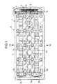
- FIG.1 to 9 illustrate a presently preferred embodiment of the present invention, wherein
- Fig.1 is a plan view illustrating an in-line type 4-cylinder engine E in a state in which a head cover has been removed.
- the direction of an arrow FR is front (on an intake side), and the direction of an arrow RR is rear (on an exhaust side).
- a head cover coupling surface 1 1 is formed around an upper surface of a cylinder head 1 to which a lower surface of the head cover is coupled.
- a timing chain 3 for transmitting the rotation of a crankshaft (not shown) to a valve operating device is accommodated in a timing chain chamber 2 which is defined on one side (a right side of a vehicle) of the engine to vertically extend through the head cover coupling surface 1 1 .
- a chain sprocket 5 is carried on an intermediate shaft 4 which is mounted in the cylinder head 1 to protrude into the timing chain chamber 2, and an upper end of the timing chain 3 is meshed with the chain sprocket 5.
- An intake cam shaft 6i and an exhaust cam shaft 6e are carried in parallel to each other in the cylinder head 1, and follower helical gears 7i and 7e provided at right ends of the intake and exhaust cam shafts 6i and 6e are meshed with a driving helical gear 8 carried on the intermediate shaft 4.
- the rotation of the crankshaft is transmitted through the timing chain 3, the chain sprocket 5, the intermediate shaft 4, the driving helical gear 8 and the follower helical gears 7i and 7e to the intake and exhaust cam shafts 6i and 6e to drive the intake and exhaust cam shafts 6i and 6e at a number of revolutions one half of that of the crankshaft.
- lower cam shaft holders 9 1 , 9 2 , 9 3 , 9 4 and 9 5 are juxtaposed in sequence from the right side to the left side of the vehicle body on an upper surface of the cylinder head 1.
- the intake and exhaust cam shafts 6i and 6e are rotatably carried between the lower cam shaft holders 9 1 , 9 2 , 9 3 , 9 4 and 9 5 commonly fastened to the cylinder head 1 and an upper cam shaft holder assembly 10 by threadedly inserting a total of 20 bolts 11 passed through an assembly 10 of upper cam shaft holders integrally formed and the five lower cam shafts 9 1 , 9 2 , 9 3 , 9 4 and 9 5 into the upper surface of the cylinder head 1.
- the upper cam shaft holder assembly 10 includes five upper cam shaft holders 10 1 , 10 2 , 10 3 , 10 4 and 10 5 coupled to upper surfaces of the five lower cam shaft holders 9 1 , 9 2 , 9 3 , 9 4 and 9 5 , and four connecting portions 10 6 which integrally couple the five upper cam shaft holders 10 1 , 10 2 , 10 3 , 10 4 and 10 5 to one another.
- each of the connecting portion 10 6 Provided on an upper surface of each of the connecting portion 10 6 are a spark plug guide 10 7 for mounting and removing a spark plug (not shown), reinforcing ribs 10 8 , 10 8 formed so as to intersect each other in an X-shape, and a plurality of oil return bores 10 10 for returning an oil accumulated on the upper surface of the connecting portion 10 6 downwards.
- a reinforcing rib 10 9 is provided on the upper surface of each of the upper cam shaft holders 10 1 , 10 2 , 10 3 , 10 4 and 10 5 to extend in a direction perpendicular to axes of the intake and exhaust cam shafts 6i and 6e.
- an intake port 15i and an exhaust port 15e are provided in the cylinder head 1 in correspondence to each of cylinders .
- Valve bores 16i, 16i; 16e, 16e are connected to the intake and exhaust ports 15i and 15e and opened and closed by a pair of intake valves 17i, 17i and a pair of exhaust valves 17e, 17e, respectively.
- the intake valves 17i, 17i and the exhaust valves 17e, 17e are biased in closing directions by valve springs 18i, 18i; 18e, 18e, respectively.
- An intake rocker shaft 19i and an exhaust rocker shaft 19e are supported on the five lower cam shaft holders 9 1 , 9 2 , 9 3 , 9 4 and 9 5 .
- a pair of intake rocker arms 20i, 20i are pivotally supported at one ends thereof on the intake rocker shaft 19i, with the other ends of the intake rocker arms 20i, 20i abutting against stem ends of the intake valves 17i, 17i.
- a pair of exhaust rocker arms 20e, 20e are pivotally supported at one ends thereof on the exhaust rocker shaft 19e, with the other ends of the exhaust rocker arms 20e, 20e abutting against stem ends of the exhaust valves 17e, 17e.
- Rollers 21i, 21i are provided at intermediate portions of the lower-speed intake rocker arms 20i, 20i and abut against lower-speed cams 22i, 22i provided on the intake cam shaft 6i.
- Rollers 21e, 21e are provided at intermediate portions of the lower-speed exhaust rocker arms 20e, 20e and abut against lower-speed cams 22e, 22e provided on the exhaust cam shaft 6e.
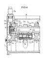
- FIG.4 An exhaust-side valve operating mechanism including the exhaust rocker shaft 19e is shown in Fig.4.
- a high-speed exhaust rocker arm 23e is pivotally supported on the exhaust rocker shaft 19e, so that it is sandwiched between the pair of lower-speed exhaust rocker arms 20e, 20e.
- the high-speed exhaust rocker arm 23e abuts against a high-speed cam 24e provided on the exhaust cam shaft 6e.
- the high-speed exhaust rocker arm 23e and the lower-speed exhaust rocker arms 20e, 20e are capable of being connected to and disconnected from each other by a variable valve timing/lifting mechanism 25.
- the structure of the variable valve timing/lifting mechanism 25 is know and is not described herein in detail.
- the structure of an intake-side valve operating mechanism is substantially the same as that of the above-described exhaust-side valve operating mechanism.
- the high-speed rocker arms 23i and 23e are coupled to the low-speed rocker arms 20i, 20i; 20e, 20e by the variable valve timing/lifting mechanism 25, and the intake valves 17i, 17i and the exhaust valves 17e, 17e are driven by profiles of the high-speed cams 24i and 24e.
- the high-speed rocker arms 23i and 23e are disengaged from the low-speed rocker arms 20i, 20i;20e, 20e by the variable valve timing/lifting mechanism 25, and the intake valves 17i, 17i and the exhaust valves 17e, 17e are driven by profiles of the low-speed cams 22i, 22i; 22e, 22e.
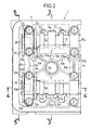
- first thrust limiting members 31i and 31e and second thrust limiting members 32i and 32e are mounted at left axial ends of the intake and exhaust cam shafts 6i and 6e.
- Each of the first thrust limiting members 31i and 31e is a disk-like member and integrally formed on each of the intake and exhaust cam shafts 6i and 6e.
- each of the second thrust limiting members 32i and 32e is a substantially disk-like member having three detected projections 33i, 33e spaced at distances of 90° from each other on an outer periphery thereof, respectively, and is fitted into a stepped portion 6 1 , 6 1 (see Figs.4 and 5) at an axial end of each of the intake and exhaust cam shafts 6i and 6e and fixed by a bolt 35, 35 in a state in which it has been positioned in a rotating direction by a positioning pin 34, 34.
- TDC a top dead center of a piston
- TDC sensor 37i for detecting the three detected projections 33i of the second thrust limiting member 32i on the side of the intake cam shaft 6i
- TDC sensor 37e for detecting the three detected projections 33e of the second thrust limiting member 32e on the side of the exhaust cam shaft 6e.
- the TDC sensors 37i and 37e are disposed in radiate directions with respect to the cam shafts 6i and 6e, respectively, and in planes of rotation of the second thrust limiting members 32i and 32e in order to shorten the axial dimension of the engine E.
- a bonnet 39 covering an upper portion of the engine E is inclined downwards toward the forward direction, so that the front side (intake side) is lower and the rear side (exhaust side) is higher.
- the interference of the TDC sensors 37i and 37e with the bonnet 39 can be avoided while suppressing the gap between the head cover 36 and the bonnet 39 to the minimum by supporting the TDC sensor 37i on the side of the intake cam shaft 6i substantially horizontally on the front surface of the head cover 36 and supporting the TDC sensor 37e on the side of the exhaust cam shaft 6e substantially vertically on the upper surface of a rear portion of the head cover 36.
- each of the three detected projections 33i, 33e of the second thrust limiting members 32i and 32e can be detected by the TDC sensors 37i and 37e, and TDC of the four cylinders can be detected based on a timing of the detection of such passage.
- Three upper cam shaft holder coupling surfaces 42 are formed on an upper surface of the #5 lower cam shaft holder 9 5 and separated from one another by a pair of semi-circular cam shaft support portions 41, 41 which support the cam shafts 6i and 6e, and two cylinder head coupling surfaces 43, 43 are formed on a lower surface of the #5 lower cam shaft holder 9 5 and separated from each other at a central point of such lower surface.
- Four bolt bores 44 are provided in the upper cam shaft holder coupling surfaces 42 and the cylinder head coupling surfaces 43 to extend through these surfaces 42 and 43, and the bolts 11 are passed through the bolt bores 44.
- Two rocker shaft-supporting boss portions 45i and 45e are projectingly provided on a right side (i.e. , a side on the side of the #4 lower rocker shaft holder 9 4 ) of the #5 lower cam shaft holder 9 5 , and the intake-side rocker arm 19i and the exhaust-side rocker arm 19e are supported in fitted states on the rocker shaft supporting boss portions 45i and 45e.
- a pair of protrusions 43 1 , 43 1 connected to the cylinder head coupling surfaces 43, 43 are formed by extension of the pair of rocker shaft supporting boss portions 45i and 45e to the cylinder head coupling surfaces 43, 43.
- a pair of protrusions 43 2 , 43 2 connected to the cylinder head coupling surfaces 43, 43 are integrally formed at a lower portion of a left side (i.e., a side on the opposite side from the #4 lower rocker shaft holder 9 4 ) of the #5 lower cam shaft holder 9 5 .
- First thrust load supporting surfaces 46, 46 are formed on the right side of the #5 lower cam shaft holder 9 5 to surround the cam shaft supporting portions 41, 41, and the first thrust limiting members 31i and 31e are in sliding contact with the first thrust load supporting surfaces 46, 46.
- Second thrust load supporting surfaces 47, 47 are formed on the left side of the #5 lower cam shaft holder 9 5 to surround the cam shaft supporting portions 41, 41, and the second thrust limiting members 32i and 32e are in sliding contact with the second thrust load supporting surfaces 47, 47.
- the #5 upper cam shaft holder 10 5 similarly has first and second thrust load supporting surfaces 48,48; 49,49 as shown in Figs. 3 and 5.
- reinforcing ribs 9 6 , 9 6 intersecting each other in an X-shape are formed on the right side of the #5 lower cam shaft holder 9 5 to connect the pair of cam shaft supporting portions 41, 41 and the pair of rocker shaft supporting boss portions 45i and 45e to each other.
- Reinforcing ribs 9 7 , 9 7 mirror-symmetrical with the reinforcing ribs 9 6 , 9 6 are also formed on the left side of the #5 lower cam shaft holder 9 5 (see Fig.5).
- the thrust load is supported to limit the axial movements of the cam shafts 6i and 6e by the abutment of the first thrust limiting members 31i and 31e against the first thrust load supporting surfaces 46, 46; 48, 48 (see Fig.3) formed on the right sides of the #5 lower cam shaft holder 9 5 and the #5 upper cam shaft holder 10 5 , or by the abutment of the second thrust limiting members 32i and 32e against the second thrust load supporting surfaces 47, 47; 49, 49 (see Fig.5) formed on the left sides of the #5 lower cam shaft holder 9 5 and the #5 upper cam shaft holder 10 5 .
- the detected projections 33i and 33e adapted to be detected by the TDC sensors 37i and 37e are formed on the outer peripheries of the second thrust limiting members 32i and 32e, the conventional need for provision of a special rotatable plate having a detected projection is eliminated, leading to a reduction in number of parts.
- the detected projections 33i and 33e are provided on the second thrust limiting members 32i and 32e which limit the axial movements of the cam shafts 6i and 6e, the stable rotation of the detected projections 33i and 33e can be ensured, and the variation in axial position of the detected projections 33i and 33e caused due to an influence of the thermal expansion of the cam shafts 6i and 6e can be suppressed to the minimum to prevent a reduction in detecting accuracy of the TDC sensors 37i and 37e and to enhance the degree of freedom of the layout of the TDC sensors 37i and 37e.
- the thrust load supporting surfaces 46, 46, 47, 47 are formed adjacent the cam shaft supporting portions 41, 41 of the #5 lower cam shaft holder 9 5 , the variation in rotation of the detected projections 33i and 33e can be further effectively prevented to enhance the detecting accuracy of the TDC sensors 37i and 37e.
- the axial movement of the #5 lower cam shaft holder 9 5 can be prevented to further reliably support the cam shafts 6i and 6e to enhance the detecting accuracy of the TDC sensors 37i and 37e by the fact that the protrusions 43 1 , 43 1 ; 43 2 , 43 2 projecting axially of the cam shafts 6i and 6e are formed on the cylinder head coupling surface 43 of the #5 lower cam shaft holder 9 5 .
- the protrusions 43 1 , 43 1 are connected to the rocker shaft supporting boss portions 45i and 45e, the support rigidity of the rocker shaft 19i and 19e is also enhanced.
- the thrust load applied to the upper cam shaft holder 10 5 can be dispersed to the #1 to #4 lower cam holders 9 1 to 9 4 through the #1 to #4 upper cam holders 10 1 to 10 4 to further effectively prevent the axial movement of the #5 upper cam shaft holder 10 5 and the #5 lower cam shaft holder 9 5 .
- the detected projections 33i and 33e are provided on those thrust limiting members 32i and 32e of the first and second thrust limiting members 31i, 31e, 32i and 32e sandwiching the #5 lower and upper cam shaft holders 9 5 and 10 5 , which are located at the axial ends of the cam shafts 6i and 6e and above which there is not the connecting portion 10 6 of the upper cam shaft holder assembly 10, the detected projections 33i and 33e cannot interfere with the connecting portions 10 6 , even if the height of the connecting portion 10 6 from the upper surface of the #5 lower cam shaft holder 9 5 is decreased to reduce the vertical dimension of the engine E.
- the size of the second thrust limiting members 32i and 32e having the detected projections 33i and 33e can be increased without increasing the size of the engine E to enhance the detecting accuracy.
- the engine rotation detecting system is not limited to the use for the detection of the rotated position of the phase of the cam shafts 6i and 6e described above, but is also applicable to the detection of the rotated position, the rotational angle and the number of rotations of the rotary shaft (the crankshaft or the like) of the engine other than the cam shafts 6i and 6e.
- the detected projections 33i, 32e are provided on the thrust limiting members 32i, 32e formed separate from the cam shafts 6i and 6e in the embodiment, they may be provided on thrust limiting members formed integral with the cam shaft 6i and 6e.
- a first thrust limiting member and a second thrust limiting member are provided on a cam shaft rotatably carried between a lower cam shaft holder and an upper cam shaft holder which are fixed to an upper surface of a cylinder head 1, so that the first and second thrust limiting members and abut against the cam shaft holders 9 5 and 10 5 .
- the second thrust limiting member has a plurality of detected projections provided around of an outer periphery thereof, so that the detected projections are detected by a TDC sensor 37 mounted to a head cover of the engine.
- the rotated position (phase), the angle of rotation and the number of rotations of an rotary shaft of an engine such as a cam shaft 6e and a crankshaft can be detected with good accuracy in a structure including a decreased number of parts, and the axial dimension of the rotary shaft of the engine can be reduced.
Landscapes
- Engineering & Computer Science (AREA)
- Mechanical Engineering (AREA)
- General Engineering & Computer Science (AREA)
- Chemical & Material Sciences (AREA)
- Combustion & Propulsion (AREA)
- Physics & Mathematics (AREA)
- Electromagnetism (AREA)
- Valve-Gear Or Valve Arrangements (AREA)
- Cylinder Crankcases Of Internal Combustion Engines (AREA)
Claims (13)
- Motordrehungserfassungssystem, umfassend einen erfassten Abschnitt (33i, 33e), welcher an einer Nockenwelle (6i, 6e) vorgesehen ist, die zwischen einem oberen Nockenwellenhalter (105) und einem an einen Zylinderkopf (1) eines Motors (E) montierten unteren Nockenwellenhalter (95) gelagert ist, sowie einen Sensor (37i, 37e) zur Erfassung einer Position des erfassten Abschnitts (33i, 33e), wobei der erfasste Abschnitt (33i, 33e) an einem an die Nockenwelle (6i, 6e) montierten Schubbegrenzungselement (32i, 32e) vorgesehen ist, wobei das Schubbegrenzungselement dazu ausgebildet ist, eine axiale Bewegung der Nockenwelle (6i, 6e) zu begrenzen und ferner dazu ausgebildet ist, eine axiale Verlagerung des erfassten Abschnitts (33i, 33e) zu unterdrücken, wobei der untere Nockenwellenhalter (95) mit einem Anlageabschnitt (46, 47) ausgebildet ist, gegen welchen das Schubbegrenzungselement (32i, 32e) in Anlage ist, und wobei der untere Nockenwellenhalter (95) eine Zylinderkopf-Kopplungsfläche (43) aufweist, welche mit einem Vorsprung (431, 432) ausgebildet ist, der von dem Anlageabschnitt (46, 47) in einer axialen Richtung der Nockenwelle (6i, 6e) vorsteht.
- Motordrehungserfassungssystem nach Anspruch 1, wobei die Nockenwelle (6i, 6e) zwischen einer Mehrzahl von oberen Nockenwellenhaltern (101, 102, 103, 104, 105) und einer Mehrzahl von an einen Zylinderkopf (1) montierten unteren Nockenwellenhaltern (91, 92, 93, 94, 95) gelagert ist, wobei die oberen Nockenwellenhalter (101, 102, 103, 104, 105) miteinander durch Verbindungsabschnitte (106) verbunden sind, welche in einer axialen Richtung der Nockenwelle (6i, 6e) verlaufen, wobei der Motor (E) ein zweites Schubbegrenzungselement (32i, 32e) an der Nockenwelle (6i, 6e) umfasst und die zwei Schubbegrenzungselemente (31i, 31e, 32i, 32e) an entgegengesetzten Seiten eines endseitigen (95) der unteren Nockenwellenhalter (91, 92, 93, 94, 95) bezüglich der axialen Richtung angeordnet sind, wobei der erfasste Abschnitt (33i, 33e) an dem Außenumfang eines äußersten (32i, 32e) der zwei Schubbegrenzungselemente (31 i, 31 e, 32i, 32e) vorgesehen ist.
- Motordrehungserfassungssystem nach Anspruch 2, bei welchem der äußerste (32i, 32e) der zwei Schubbegrenzungselemente (31 i, 31 e, 32i, 32e) dem endseitigen (95) der unteren Nockenwellenhalter (91, 92, 93, 94, 95) benachbart gelegen ist.
- Motordrehungserfassungssystem nach Anspruch 1, bei welchem der obere (105) und der untere Nockenwellenhalter (95) gemeinsam einen Nockenwellenhalter (95, 105) bilden, wobei der Motor (E) ein zweites Schubbegrenzungselement (32i, 32e) an der Nockenwelle (6i, 6e) aufweist und die zwei Schubbegrenzungselemente (31 i, 31 e, 32i, 32e) an entgegengesetzten Seiten des Nockenwellenhalters (95, 105) angeordnet sind, welcher nahe eines Endes der Nockenwelle (6i, 6e) in ihrer axialen Richtung vorgesehen ist, wobei der erfasste Abschnitt an einem der zwei Schubbegrenzungselemente (31i, 31e, 32i, 32e) vorgesehen ist, welcher dem Ende der Nockenwelle (6i, 6e) benachbart gelegen ist, und wobei der Sensor (37i, 37e) an einer Stelle montiert ist, welche dem erfassten Abschnitt (33i, 33e) gegenüber liegt.
- Motordrehungserfassungssystem nach einem der Ansprüche 2 bis 4, bei welchem eines (31 i, 31 e) der zwei Schubbegrenzungselemente (31i, 31 e, 32i, 32e), welches in axialer Richtung einwärts des Endes der Nockenwelle (6i, 6e) gelegen ist, integral mit der Nockenwelle (6i, 6e) ausgebildet ist, und das andere der Schubbegrenzungselemente (32i, 32e) von der Nockenwelle (6i, 6e) gesondert ausgebildet ist.
- Motordrehungserfassungssystem nach einem der Ansprüche 2 bis 5, bei welchem ein entgegengesetztes Ende der Nockenwelle (6i, 6e) einen Antriebsmechanismus (7i, 7e) für die damit verbundene Nockenwelle (6i, 6e) aufweist.
- Motordrehungserfassungssystem nach einem der vorhergehenden Ansprüche, bei welchem das Schubbegrenzungselement (32i, 32e), welches den erfassten Abschnitt (33i, 33e) an sich vorgesehen aufweist, an dem axialen Ende der Nockenwelle (6i, 6e) durch eine Schraube (35) und einen Positionierstift (34) nicht drehbar festgelegt ist.
- Motordrehungserfassungssystem nach einem der vorhergehenden Ansprüche, bei welchem der Vorsprung (431, 432) einen Kipphebellager-Vorsprungsabschnitt (45i, 45e) des unteren Nockenwellenhalters (95) umfasst, welcher nach unten zu der Zylinderkopf-Kopplungsfläche (43) ausgedehnt ist.
- Motordrehungserfassungssystem nach einem der vorhergehenden Ansprüche 2 bis 8, bei welchem jeder Verbindungsabschnitt (106) an seinem zentralen Abschnitt eine Kerzenführung (107) ausgebildet aufweist, um eine Zündkerze anzubringen und zu lösen.
- Motordrehungserfassungssystem nach Anspruch 9, ferner umfassend Rippen (108), welche derart ausgebildet sind, dass sie in radialer Richtung von den Kerzenführungen (107) zu Nockenhalterbefestigungsabschnitten der oberen Nockenwellenhalter (101, 102, 103, 104, 105) verlaufen.
- Motordrehungserfassungssystem nach einem der vorhergehenden Ansprüche, bei welchem der Sensor (37i, 37e) an eine Kopfabdeckung (36) des Motors (E) montiert ist.
- Motordrehungserfassungssystem nach Anspruch 1, bei welchem der Sensor (37i, 37e) für jede der zwei Nockenwellen (6i, 6e) des Motors (E) vorgesehen ist und der erfasste Abschnitt (33i, 33e) an jedem der Schubbegrenzungselemente (32i, 32e) vorgesehen ist, wobei die Schubbegrenzungselemente dazu ausgebildet sind, die axiale Bewegung der zwei Nockenwellen (6i, 6e) zu begrenzen und ferner dazu ausgebildet sind, eine axiale Verlagerung der erfassten Abschnitte (33i, 33e) zu unterdrücken, und wobei jede der zwei Nockenwellen (6i, 6e) einen Nockenwellenantriebsmechanismus (7i, 7e) in axialer Richtung an einem Ende derselben vorgesehen aufweist, und den erfassten Abschnitt (33i, 33e) an dem anderen Ende derselben vorgesehen aufweist.
- Motordrehungserfassungssystem nach einem der vorhergehenden Ansprüche, wobei der erfasste Abschnitt (33i, 33e) in einer radialen Richtung von einem Außenumfang des Schubbegrenzungselements (32i, 32e) vorsteht.
Applications Claiming Priority (3)
| Application Number | Priority Date | Filing Date | Title |
|---|---|---|---|
| JP9507996 | 1996-04-17 | ||
| JP8095079A JP2913273B2 (ja) | 1996-04-17 | 1996-04-17 | エンジンの回転検出装置 |
| JP95079/96 | 1996-04-17 |
Publications (3)
| Publication Number | Publication Date |
|---|---|
| EP0802323A2 EP0802323A2 (de) | 1997-10-22 |
| EP0802323A3 EP0802323A3 (de) | 2000-03-15 |
| EP0802323B1 true EP0802323B1 (de) | 2003-11-19 |
Family
ID=14127959
Family Applications (1)
| Application Number | Title | Priority Date | Filing Date |
|---|---|---|---|
| EP97106184A Expired - Lifetime EP0802323B1 (de) | 1996-04-17 | 1997-04-15 | Maschinenumdrehungerkennungssystem |
Country Status (7)
| Country | Link |
|---|---|
| US (1) | US5948973A (de) |
| EP (1) | EP0802323B1 (de) |
| JP (1) | JP2913273B2 (de) |
| KR (1) | KR100253516B1 (de) |
| CN (1) | CN1099585C (de) |
| DE (1) | DE69726214T2 (de) |
| TW (1) | TW320674B (de) |
Families Citing this family (14)
| Publication number | Priority date | Publication date | Assignee | Title |
|---|---|---|---|---|
| JP4093682B2 (ja) * | 1999-05-28 | 2008-06-04 | 本田技研工業株式会社 | 4サイクルエンジンの行程判別装置 |
| JP3604304B2 (ja) * | 1999-09-03 | 2004-12-22 | 本田技研工業株式会社 | カム軸回転センサの取付部の構造 |
| JP2001329885A (ja) * | 2000-05-18 | 2001-11-30 | Yamaha Motor Co Ltd | エンジンのカム角センサ搭載構造 |
| US7191641B2 (en) * | 2002-10-24 | 2007-03-20 | Ford Global Technologies, Llc | Rotary position sensing assembly for internal combustion engine |
| JP4102694B2 (ja) * | 2003-03-27 | 2008-06-18 | 日野自動車株式会社 | タイミングギヤの位相合わせ装置 |
| JP4151469B2 (ja) * | 2003-04-22 | 2008-09-17 | 日産自動車株式会社 | カムシャフト回転角検出構造 |
| DE10347516B3 (de) * | 2003-10-13 | 2005-06-02 | Siemens Ag | Verfahren und Vorrichtung zum Ermitteln einer Phasenlage einer Nockenwelle einer Brennkraftmaschine |
| JP4382010B2 (ja) * | 2005-06-23 | 2009-12-09 | 本田技研工業株式会社 | エンジンの動弁装置 |
| JP5171427B2 (ja) | 2008-06-23 | 2013-03-27 | ダイハツ工業株式会社 | 内燃機関におけるカム角度センサの取付け装置 |
| JP5149268B2 (ja) * | 2009-12-25 | 2013-02-20 | 本田技研工業株式会社 | 回転角センサ取り付け構造及び同構造を用いた内燃機関の可変動弁装置 |
| US8800517B2 (en) | 2010-12-01 | 2014-08-12 | Caterpillar Inc. | Cam shaft/cam gear assembly and thrust strategy for engine using same |
| JP5785482B2 (ja) | 2011-11-25 | 2015-09-30 | 本田技研工業株式会社 | 内燃機関のカムシャフト支持構造 |
| JP2013155647A (ja) * | 2012-01-27 | 2013-08-15 | Suzuki Motor Corp | 3次元カム用カムハウジング構造 |
| JP6349425B2 (ja) * | 2017-02-15 | 2018-06-27 | 本田技研工業株式会社 | 4ストローク内燃機関のロッカー軸配置構造 |
Family Cites Families (14)
| Publication number | Priority date | Publication date | Assignee | Title |
|---|---|---|---|---|
| JPS61184916A (ja) * | 1985-02-12 | 1986-08-18 | Matsushita Electric Ind Co Ltd | 受信機 |
| JPS6226566A (ja) * | 1985-07-26 | 1987-02-04 | Fanuc Ltd | デ−タ授受方法 |
| US4762097A (en) * | 1986-12-29 | 1988-08-09 | General Motors Corporation | Engine with hydraulically variable cam timing |
| JPH01124707A (ja) * | 1987-11-09 | 1989-05-17 | Mitsubishi Electric Corp | 内燃機関用回転位置検出装置 |
| DE3816114A1 (de) * | 1988-05-11 | 1989-11-23 | Porsche Ag | Abtastvorrichtung zur drehzahlmessung an einer brennkraftmaschine |
| JPH082403Y2 (ja) * | 1989-05-22 | 1996-01-29 | トヨタ自動車株式会社 | カムシャフトおよび組付ライン共用のためのスラスト軸受構造 |
| JP3244715B2 (ja) * | 1991-03-15 | 2002-01-07 | ヤマハ発動機株式会社 | エンジンの気筒判別センサ配置構造 |
| DE4116944C2 (de) * | 1991-05-24 | 1997-05-22 | Daimler Benz Ag | Zylinderkopf für eine mehrzylindrige Brennkraftmaschine |
| DE69219077T2 (de) * | 1991-11-12 | 1997-11-13 | Chrysler Corp | Sensor für Zündanlage |
| US5548995A (en) * | 1993-11-22 | 1996-08-27 | Ford Motor Company | Method and apparatus for detecting the angular position of a variable position camshaft |
| FR2713278B1 (fr) * | 1993-12-03 | 1996-01-05 | Renault | Dispositif de détection de la position angulaire d'un arbre à cames de moteur à combustion interne. |
| JPH0868346A (ja) * | 1994-08-26 | 1996-03-12 | Yamaha Motor Co Ltd | エンジンの角度センサ装置 |
| FR2739145B1 (fr) * | 1995-09-25 | 1998-12-18 | Bosch Gmbh Robert | Procede de detection des rates de combustion d'un moteur a combustion interne |
| US5715780A (en) * | 1996-10-21 | 1998-02-10 | General Motors Corporation | Cam phaser position detection |
-
1996
- 1996-04-17 JP JP8095079A patent/JP2913273B2/ja not_active Expired - Fee Related
-
1997
- 1997-04-15 EP EP97106184A patent/EP0802323B1/de not_active Expired - Lifetime
- 1997-04-15 US US08/838,081 patent/US5948973A/en not_active Expired - Lifetime
- 1997-04-15 DE DE69726214T patent/DE69726214T2/de not_active Expired - Lifetime
- 1997-04-16 TW TW086104906A patent/TW320674B/zh active
- 1997-04-16 CN CN97110737A patent/CN1099585C/zh not_active Expired - Fee Related
- 1997-04-17 KR KR1019970014183A patent/KR100253516B1/ko not_active Expired - Fee Related
Also Published As
| Publication number | Publication date |
|---|---|
| EP0802323A3 (de) | 2000-03-15 |
| JPH09280084A (ja) | 1997-10-28 |
| KR100253516B1 (ko) | 2000-04-15 |
| DE69726214T2 (de) | 2004-04-22 |
| TW320674B (de) | 1997-11-21 |
| CN1099585C (zh) | 2003-01-22 |
| EP0802323A2 (de) | 1997-10-22 |
| KR970070977A (ko) | 1997-11-07 |
| DE69726214D1 (de) | 2003-12-24 |
| CN1167255A (zh) | 1997-12-10 |
| JP2913273B2 (ja) | 1999-06-28 |
| US5948973A (en) | 1999-09-07 |
Similar Documents
| Publication | Publication Date | Title |
|---|---|---|
| US5948973A (en) | Engine-rotation detecting system | |
| US8127739B2 (en) | Variable stroke engine | |
| JPS6133970B2 (de) | ||
| US5987973A (en) | Rotation detecting device of an engine | |
| JP2611838B2 (ja) | Dohcエンジンのカム軸軸受構造 | |
| JP3727362B2 (ja) | エンジンの可変バルブタイミング装置 | |
| US7305938B2 (en) | Stroke-variable engine | |
| KR950003060B1 (ko) | 엔진의 구동밸브장치의 조립방법 | |
| US6953015B2 (en) | Engine | |
| EP1191203A2 (de) | Zusammensetzung für die Massenbalancierung einer V-Typ-Brennkraftmaschine | |
| JP3261313B2 (ja) | エンジンの回転検出装置 | |
| EP2136049B1 (de) | Brennkraftmaschine mit variablen Kolbenhub | |
| JP3327322B2 (ja) | バルブタイミング可変装置を備えた4サイクルエンジン | |
| JP3290624B2 (ja) | 並列2気筒エンジン | |
| JP2004052708A (ja) | 多気筒エンジン | |
| EP1207274B1 (de) | Ventiltriebsystem in einer Vierzylinder-Brennkraftmaschine mit obenliegenden Ventilen | |
| JP3712461B2 (ja) | 頭上弁式内燃機関のシリンダヘッド | |
| JP2008138607A (ja) | ストローク特性可変エンジン | |
| JPH108987A (ja) | 4サイクルエンジンのチェーンカバー構造 | |
| JP3309700B2 (ja) | 4サイクルエンジン | |
| EP0661418B1 (de) | Brennkraftmaschine | |
| JPH0245444Y2 (de) | ||
| JPH0113786Y2 (de) | ||
| KR0167928B1 (ko) | 링크방식을 이용한 dohc형 캠 샤프트 구동장치 | |
| JP2004052707A (ja) | エンジン |
Legal Events
| Date | Code | Title | Description |
|---|---|---|---|
| PUAI | Public reference made under article 153(3) epc to a published international application that has entered the european phase |
Free format text: ORIGINAL CODE: 0009012 |
|
| AK | Designated contracting states |
Kind code of ref document: A2 Designated state(s): DE GB |
|
| PUAL | Search report despatched |
Free format text: ORIGINAL CODE: 0009013 |
|
| AK | Designated contracting states |
Kind code of ref document: A3 Designated state(s): DE GB |
|
| RIC1 | Information provided on ipc code assigned before grant |
Free format text: 7F 02P 7/067 A, 7F 01L 1/26 B, 7F 02D 41/24 B, 7F 01L 1/46 B, 7F 01L 1/053 B |
|
| 17P | Request for examination filed |
Effective date: 20000914 |
|
| 17Q | First examination report despatched |
Effective date: 20020603 |
|
| GRAH | Despatch of communication of intention to grant a patent |
Free format text: ORIGINAL CODE: EPIDOS IGRA |
|
| GRAS | Grant fee paid |
Free format text: ORIGINAL CODE: EPIDOSNIGR3 |
|
| GRAA | (expected) grant |
Free format text: ORIGINAL CODE: 0009210 |
|
| AK | Designated contracting states |
Kind code of ref document: B1 Designated state(s): DE GB |
|
| REG | Reference to a national code |
Ref country code: GB Ref legal event code: FG4D |
|
| REF | Corresponds to: |
Ref document number: 69726214 Country of ref document: DE Date of ref document: 20031224 Kind code of ref document: P |
|
| PLBE | No opposition filed within time limit |
Free format text: ORIGINAL CODE: 0009261 |
|
| STAA | Information on the status of an ep patent application or granted ep patent |
Free format text: STATUS: NO OPPOSITION FILED WITHIN TIME LIMIT |
|
| 26N | No opposition filed |
Effective date: 20040820 |
|
| PGFP | Annual fee paid to national office [announced via postgrant information from national office to epo] |
Ref country code: GB Payment date: 20090415 Year of fee payment: 13 |
|
| GBPC | Gb: european patent ceased through non-payment of renewal fee |
Effective date: 20100415 |
|
| PG25 | Lapsed in a contracting state [announced via postgrant information from national office to epo] |
Ref country code: GB Free format text: LAPSE BECAUSE OF NON-PAYMENT OF DUE FEES Effective date: 20100415 |
|
| REG | Reference to a national code |
Ref country code: DE Ref legal event code: R084 Ref document number: 69726214 Country of ref document: DE Effective date: 20120209 |
|
| PGFP | Annual fee paid to national office [announced via postgrant information from national office to epo] |
Ref country code: DE Payment date: 20120425 Year of fee payment: 16 |
|
| PG25 | Lapsed in a contracting state [announced via postgrant information from national office to epo] |
Ref country code: DE Free format text: LAPSE BECAUSE OF NON-PAYMENT OF DUE FEES Effective date: 20131101 |
|
| REG | Reference to a national code |
Ref country code: DE Ref legal event code: R119 Ref document number: 69726214 Country of ref document: DE Effective date: 20131101 |