EP0802326B1 - Machine à engrenages à gradient de pression contrôlé - Google Patents
Machine à engrenages à gradient de pression contrôlé Download PDFInfo
- Publication number
- EP0802326B1 EP0802326B1 EP96105855A EP96105855A EP0802326B1 EP 0802326 B1 EP0802326 B1 EP 0802326B1 EP 96105855 A EP96105855 A EP 96105855A EP 96105855 A EP96105855 A EP 96105855A EP 0802326 B1 EP0802326 B1 EP 0802326B1
- Authority
- EP
- European Patent Office
- Prior art keywords
- gears
- pressure
- machine according
- distribution spaces
- displacing machine
- Prior art date
- Legal status (The legal status is an assumption and is not a legal conclusion. Google has not performed a legal analysis and makes no representation as to the accuracy of the status listed.)
- Expired - Lifetime
Links
- 238000007789 sealing Methods 0.000 claims description 14
- 230000001747 exhibiting effect Effects 0.000 claims 5
- 238000011144 upstream manufacturing Methods 0.000 claims 1
- 238000006073 displacement reaction Methods 0.000 description 23
- 230000010349 pulsation Effects 0.000 description 9
- 239000012530 fluid Substances 0.000 description 8
- 238000000926 separation method Methods 0.000 description 6
- 230000002093 peripheral effect Effects 0.000 description 3
- 230000001419 dependent effect Effects 0.000 description 2
- 238000004519 manufacturing process Methods 0.000 description 2
- 238000005516 engineering process Methods 0.000 description 1
- 230000001737 promoting effect Effects 0.000 description 1
Images
Classifications
-
- F—MECHANICAL ENGINEERING; LIGHTING; HEATING; WEAPONS; BLASTING
- F04—POSITIVE - DISPLACEMENT MACHINES FOR LIQUIDS; PUMPS FOR LIQUIDS OR ELASTIC FLUIDS
- F04C—ROTARY-PISTON, OR OSCILLATING-PISTON, POSITIVE-DISPLACEMENT MACHINES FOR LIQUIDS; ROTARY-PISTON, OR OSCILLATING-PISTON, POSITIVE-DISPLACEMENT PUMPS
- F04C15/00—Component parts, details or accessories of machines, pumps or pumping installations, not provided for in groups F04C2/00 - F04C14/00
- F04C15/0042—Systems for the equilibration of forces acting on the machines or pump
Definitions
- the invention relates to a displacement machine two intermeshing, externally toothed gears according to the preamble of claim 1.
- Displacement machines are known. Such machines are characterized by high running noise as well relatively strong flow pulsations that are disruptive and are therefore undesirable.
- Tolerances pinion head circle and housing inner diameter
- the gears act so that they are radial with be subjected to a force.
- the wheels are loaded by a drive torque.
- the forces acting on a gear result a resulting force whose line of action with the line of action of the resulting power of the other Gear diverges, that is, the gears become by the resulting resulting directed away from each other Forces pressed apart.
- a displacement machine is used to solve this task proposed that mentioned in claim 1 Features. Because the im the higher Prevailing connection area Pressure over a peripheral area of the gears to the one with the lower pressure level Connection area is returned, whereby the Gears pressed against each other by hydraulic forces are guaranteed in a simple way, that the resulting resulting on the gears Forces or their lines of action in an area on the suction side to cut. This causes the movements the gears are facing each other, which makes the teeth in the area where they are together comb, be pushed together so that on the one hand the backlash of the gears and on the other hand the space is reduced, the two teeth include with each other.
- the reduction of the included Room volume leads directly to one Reduction of the enclosed in this room also referred to as the squeeze volume of fluid and thus to a significant reduction the flow pulsation, i.e. the pressure vibrations in the connection area with the higher pressure level, due to this the sound power level the displacement machine is significantly reduced is.
- the fact that the first pressure distribution rooms over a circumferential area of the gears of Extend 70 ° and approximately symmetrical to the axis of symmetry lie and that the second pressure distribution rooms - starting from the first - to the Extend circumferential area of the gears, the 45 ° in front of the suction area are the noise level and further reduces the flow pulsation.
- connection areas separated from each other by a double flank seal are:
- the gears are affected by those acting on them resulting forces towards each other moved that the meshing teeth the Suction side and pressure side by means of three touch or Separate sealing points.
- the thus trained Double-flank sealing is thus realized that a tooth with its two flanks simultaneously on the flanks of two teeth of the other Gear rolls, which permanently three Sealing points are given on an engagement line are arranged and move along this.
- the double flank seal also leads to a Reduction of the squeezing volume, which causes the flow pulsation compared to a single flank seal, the only two interventional respectively Sealing points in the separation area between suction and Printed page is reduced by 75%. Because of the proportionality between running noise and flow pulsation is the noise level reduced accordingly.
- An embodiment of the displacement machine is also preferred, where the resultant from the hydraulic radial forces and from on to the Torque acting on the axis of rotation of the gearwheels mechanical forces with an axis of symmetry each include an angle that is smaller Is 90 °. This causes in the area of by Manufacturing tolerances possible play one another too directed movement of the two gears, whereby the teeth of the gears mesh in such a way that both flanks of the suction from the Teeth on the pressure side separating a gear Flanks of one tooth of the other gear.
- the displacement machine operated as a pump that is a gear with a driving torque pressurized so that a fluid is required becomes. It is possible to understand how the Reverse displacement machine and this also as To operate the engine.
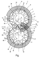
- the figure shows a schematic sectional view a displacement machine 1 with a housing, of which is shown here only the inner surface 3 of the housing is.
- the housing inner surface 3 encloses an interior 5 which on its end faces by Sealing surfaces is limited.
- the sealing surfaces are usually also referred to as printing plates Lids closed.
- the interior 5 has a cross section in Form an eight on, by two axially parallel Holes is formed.
- two externally toothed gears 11 and 13 arranged, the rotatably connected to axes of rotation 15 and 17 are and their side surfaces close to the sealing surfaces issue.
- the centers of the gears 11 and 13 each lie on an intersection, the of an axis of symmetry 19 and a plane El respectively from the axis of symmetry 19 and one Level E2 is formed.
- the levels E1 and E2 run parallel to each other and orthogonal to the axis of symmetry 19.
- the gears 11 and 13 mesh in one Separation area 21 with each other, the two connection areas 23 and 25 separates. That too promoting fluid is the lower of the pressure level having connection area 23 (suction side) conveyed to the connection area 25 (pressure side), which is a higher pressure level than the connection area 23 has.
- connection area 23 is a bore 29 in the housing of the displacement machine 1, by means of which the interior 5 with a fluid supply - not shown here - Line is connected.
- the case points a further bore 31 on the connection area 25 is arranged and in which the of the conveying spaces 27 delivered, pressurized fluid the displacer 1 promoted and for example is supplied to a consumer.
- the desired game between the tooth heads 37 of the Gears 11 and 13 and the housing inner surface 3 leads to that of the one having the higher pressure level Connection area 25 the pressure over the peripheral area of the gears in the direction of Connection area 23 expands.
- the one on the scope The pressure applied to each of the gears creates two gears one facing the center of the gear Radial force by one by the drive torque generated mechanical force superimposed becomes.
- the radial force and the mechanical Force can be added to a vector by vectorial addition resulting force, in the following briefly resultant called, are summarized, their direction of action or line through the center of the corresponding gear.
- the groove-like pressure distribution space 33 is symmetrical trained to the axis of symmetry 19 and in this exemplary embodiment in the sealing surface 9 brought in.
- a pressure distribution room 35 Extending from the pressure distribution space 33 there is a groove-like channel in the direction of the connection area 23, here as a pressure distribution room 35 is designated.
- the pressure distribution space 35 has a tapering towards the suction side Cross-section and leads on the pressure side prevailing system pressure up to approximately 45 ° before Bore 29 of the connection area 23 back.
- the pressure distribution space 35 in the housing the displacement machine 1 or in the inner surface of the housing 3 another pressure return duct, -bore, groove or the like provided his.
- the positioning of the pressure distribution rooms 33 and 35 in or on the displacement machine is generally freely selectable. It's important, that the system pressure is defined on the periphery of the Gears is distributable that the gears are pressed against each other become.
- the gear 13 has a first Print field D1, which is from the print side in Direction of the suction side over an angular range of extends approximately 230 °.
- the width of the as an annulus segment shown pressure field D1 corresponds to the maximum acting on the connection area 25 Pressure p1 (system pressure).
- a second pressure field D2 extends over an angular range of approximately 30 ° and in which there is approximately 80% of the maximum pressure p1.
- the pressure in the pressure field D2 is designated p2.
- Another, third pressure field D3 connects to the pressure field D2 and extends itself up to the bore 29 of the connection area 23.
- Pressure p3 which corresponds to approximately 10% of the maximum pressure p1.
- Due to the arrangement and Design of the pressure distribution rooms 33 and 35 is the extension of the pressure fields D1 to D3 over the circumference of the gear 13 and their pressures p1 exactly defined up to p3.
- the resulting - Radial force, not shown here, is as above already described - by a mechanical force, superimposed on the drive torque.
- the one formed from it Resulting R1 takes center stage Gear 13 and closes with the axis of symmetry 19 an angle ⁇ which is less than 90 °.
- a pressure field D4 a pressure p4, which is approximately 60% of the maximum Pressure is p1.
- the pressure forces of the Pressure fields D1 and D4 are created by the drive torque induced mechanical force a resultant R2 summarized with the Axis of symmetry 19 includes an angle ⁇ that is less than 90 °.
Landscapes
- Engineering & Computer Science (AREA)
- Mechanical Engineering (AREA)
- General Engineering & Computer Science (AREA)
- Rotary Pumps (AREA)
- Hydraulic Motors (AREA)
Claims (9)
- Machine volumétrique (1) comprenant deux roues dentées à denture extérieure (11, 13) engrenant l'une dans l'autre qui sont logées dans un carter de telle manière que les dents des roues dentées (11, 13) sont en prise de manière étanche avec une surface interne de carter (3), comprenant également des zones de raccordement (23, 25) avec deux niveaux de pression qui sont étanchées l'une par rapport à l'autre par les dents des roues dentées (11, 13) engrenant les unes dans les autres, sachant que la pression régnant dans la zone de raccordement (25) présentant le niveau de pression le plus élevé est ramenée, par l'intermédiaire d'espaces de répartition de la pression (33, 35), vers la zone de raccordement (23) présentant le niveau de pression le plus bas en passant sur une zone périphérique des roues dentées (11, 13), d'où une action exercée par la pression sur le pourtour des roues dentées (11, 13) et une compression des roues dentées l'une vers l'autre due à des forces hydrauliques, caractérisée en ce que, vu dans la direction allant de la première zone de raccordement (25) présentant le niveau de pression le plus élevé à la zone de raccordement (23) présentant le niveau de pression le plus bas, des premiers espaces de répartition de la pression (33) s'étendent sur une zone périphérique des roues dentées (11, 13) de 70° et sont disposés de manière approximativement symétrique par rapport à l'axe de symétrie (19), les centres des roues dentées (11, 13) étant situés sur l'axe de symétrie (19), et en ce que des seconds espaces de répartition de la pression (35) s'étendent, à partir des premiers espaces de répartition de la pression (33), jusque dans une zone périphérique des roues dentées (11, 13) qui est avancée de 45° par rapport à la zone de raccordement (23) présentant le niveau de pression le plus bas.
- Machine volumétrique selon la revendication 1, caractérisée en ce que les zones de raccordement (23, 25) sont séparées l'une de l'autre par un joint à deux flancs.
- Machine volumétrique selon l'une des revendications précédentes, caractérisée en ce que l'action du niveau de pression élevé sur la zone périphérique des roues dentées (11, 13) génère des forces hydrauliques radiales qui déplacent les roues dentées (11, 13) vers la surface interne (3) du carter, si bien qu'au moins deux dents de chaque roue dentée (11, 13) sont appliquées contre la surface interne (3) du carter de manière à réaliser l'étanchéité.
- Machine volumétrique selon l'une des revendications précédentes, caractérisée en ce que les résultantes (R1, R2) issues des forces hydrauliques radiales et de forces mécaniques reposant sur des couples agissant sur l'axe de rotation des roues dentées (11, 13) forment chacune avec l'axe de symétrie (19) un angle (α, β) inférieur à 90°.
- Machine volumétrique selon l'une des revendications précédentes, caractérisée en ce que la pression élevée est répartie de façon ciblée sur les zones périphériques des roues dentées (11, 13) par l'intermédiaire des premiers et des seconds espaces de répartition de la pression (33, 35).
- Machine volumétrique selon la revendication 1 ou 5, caractérisée en ce que les premiers et seconds espaces de répartition (33, 35) sont réalisés sous forme de rainure dans la surface interne (3) du carter.
- Machine volumétrique selon la revendication 5 ou 6, caractérisée en ce que les premiers et seconds espaces de répartition de la pression (33, 35), vus dans la direction radiale, sont situés dans des zones de la surface interne (3) du carter qui sont adjacentes aux dents des roues dentées (11, 13).
- Machine volumétrique selon l'une des revendications précédentes, caractérisée en ce que les premiers et seconds espaces de répartition de la pression (33, 35) sont situés dans les surfaces d'étanchéité (9) appliquées contre les surfaces latérales des roues dentées.
- Machine volumétrique selon l'une des revendications 5 à 8, caractérisée en ce que les seconds espaces de répartition de la pression (35) présentent une section transversale se rétrécissant en direction de la zone de raccordement (23) présentant le niveau de pression le plus bas.
Priority Applications (5)
| Application Number | Priority Date | Filing Date | Title |
|---|---|---|---|
| EP96105855A EP0802326B1 (fr) | 1996-04-15 | 1996-04-15 | Machine à engrenages à gradient de pression contrôlé |
| ES96105855T ES2160737T3 (es) | 1996-04-15 | 1996-04-15 | Maquina de engranajes con control del campo de presion compensado. |
| DE59607362T DE59607362D1 (de) | 1996-04-15 | 1996-04-15 | Zahnradmaschine mit kontrollierbar ausgeglichenem Druckfeld |
| US08/673,529 US5730589A (en) | 1996-04-15 | 1996-07-01 | Hydraulic displacement machine having gears pressed toward each other |
| DE19713907A DE19713907A1 (de) | 1996-04-15 | 1997-04-04 | Verdrängermaschine |
Applications Claiming Priority (1)
| Application Number | Priority Date | Filing Date | Title |
|---|---|---|---|
| EP96105855A EP0802326B1 (fr) | 1996-04-15 | 1996-04-15 | Machine à engrenages à gradient de pression contrôlé |
Publications (2)
| Publication Number | Publication Date |
|---|---|
| EP0802326A1 EP0802326A1 (fr) | 1997-10-22 |
| EP0802326B1 true EP0802326B1 (fr) | 2001-07-25 |
Family
ID=8222667
Family Applications (1)
| Application Number | Title | Priority Date | Filing Date |
|---|---|---|---|
| EP96105855A Expired - Lifetime EP0802326B1 (fr) | 1996-04-15 | 1996-04-15 | Machine à engrenages à gradient de pression contrôlé |
Country Status (4)
| Country | Link |
|---|---|
| US (1) | US5730589A (fr) |
| EP (1) | EP0802326B1 (fr) |
| DE (2) | DE59607362D1 (fr) |
| ES (1) | ES2160737T3 (fr) |
Families Citing this family (4)
| Publication number | Priority date | Publication date | Assignee | Title |
|---|---|---|---|---|
| JP3830313B2 (ja) * | 1999-09-06 | 2006-10-04 | 株式会社ジェイテクト | ギヤポンプ |
| DE10002708C1 (de) * | 2000-01-22 | 2001-07-26 | Bosch Gmbh Robert | Hydraulische Zahnradmaschine |
| US7597145B2 (en) * | 2005-05-18 | 2009-10-06 | Blue Marble Engineering, L.L.C. | Fluid-flow system, device and method |
| JP6311644B2 (ja) * | 2015-04-28 | 2018-04-18 | 株式会社Soken | ギヤポンプ装置 |
Citations (1)
| Publication number | Priority date | Publication date | Assignee | Title |
|---|---|---|---|---|
| EP0692633A1 (fr) * | 1994-07-14 | 1996-01-17 | CASAPPA S.p.A. | Pompe à engrenages |
Family Cites Families (12)
| Publication number | Priority date | Publication date | Assignee | Title |
|---|---|---|---|---|
| GB541961A (en) * | 1939-03-16 | 1941-12-19 | Frederic Mcintyre | A metering or spinning pump primarily for use in the manufacture of rayon or other synthetic fibres |
| US2624287A (en) * | 1949-10-08 | 1953-01-06 | Borg Warner | Gear pump |
| US2864315A (en) * | 1954-02-11 | 1958-12-16 | Holley Carburetor Co | Liquid pump |
| DE1264958B (de) * | 1960-10-08 | 1968-03-28 | Bosch Gmbh Robert | Zahnradpumpe oder -motor |
| US3285188A (en) * | 1963-06-17 | 1966-11-15 | Shimadzu Corp | Hydraulic gear motor or hydraulic gear pump |
| US3474736A (en) * | 1967-12-27 | 1969-10-28 | Koehring Co | Pressure loaded gear pump |
| DE2411492C2 (de) * | 1974-03-11 | 1984-07-26 | Robert Bosch Gmbh, 7000 Stuttgart | Zahnradpumpe |
| US4087216A (en) * | 1976-10-05 | 1978-05-02 | Permco, Inc. | Flow diverter pressure plate |
| US4239468A (en) * | 1978-09-08 | 1980-12-16 | The Rexroth Corporation | Apparatus for controlling pressure distribution in gear pump |
| US4311444A (en) * | 1979-04-19 | 1982-01-19 | Shumate Donald L | Pressure-balancing end plate for a reversible gear pump or motor |
| CA1162106A (fr) * | 1979-11-19 | 1984-02-14 | Charles J. Bowden | Gradient de pression pour machine hydraulique rotative |
| SU907302A1 (ru) * | 1980-01-14 | 1982-02-23 | Винницкий Проектно-Конструкторский Технологический Институт Гидроагрегатов | Шестеренна гидромашина |
-
1996
- 1996-04-15 DE DE59607362T patent/DE59607362D1/de not_active Expired - Lifetime
- 1996-04-15 EP EP96105855A patent/EP0802326B1/fr not_active Expired - Lifetime
- 1996-04-15 ES ES96105855T patent/ES2160737T3/es not_active Expired - Lifetime
- 1996-07-01 US US08/673,529 patent/US5730589A/en not_active Expired - Lifetime
-
1997
- 1997-04-04 DE DE19713907A patent/DE19713907A1/de not_active Withdrawn
Patent Citations (1)
| Publication number | Priority date | Publication date | Assignee | Title |
|---|---|---|---|---|
| EP0692633A1 (fr) * | 1994-07-14 | 1996-01-17 | CASAPPA S.p.A. | Pompe à engrenages |
Also Published As
| Publication number | Publication date |
|---|---|
| ES2160737T3 (es) | 2001-11-16 |
| US5730589A (en) | 1998-03-24 |
| DE19713907A1 (de) | 1997-11-06 |
| DE59607362D1 (de) | 2001-08-30 |
| EP0802326A1 (fr) | 1997-10-22 |
Similar Documents
| Publication | Publication Date | Title |
|---|---|---|
| DE19613833B4 (de) | Innenzahnradmaschine, insbesondere Innenzahnradpumpe | |
| DE1553057C3 (de) | Rotationskolbenmaschine | |
| DE3800324A1 (de) | Fluegelzellenverdichter | |
| EP0802326B1 (fr) | Machine à engrenages à gradient de pression contrôlé | |
| DE2608887C2 (de) | Steuerdrehschiebereinrichtung bei einer Rotationskolbenmaschine für Flüssigkeit | |
| DE1553004C3 (de) | Steuerdrehschiebereinrichtung an einer Rotationskolbenmaschine | |
| DE3605246C2 (de) | Zahnradmaschine (Pumpe oder Motor) | |
| DE102004046934B4 (de) | Hydraulische Maschine | |
| DE69013793T2 (de) | Fluidumdruck-Drehkolbenanlage und verbesserte ortsfeste Ventilplatte. | |
| EP0607497B1 (fr) | Pompe à engrenages internes avec joint d'étanchéité incorporé dans les dents | |
| DE69909339T2 (de) | Innenzahnradmotor und Verteilerventil | |
| DE19523533C2 (de) | Sauggeregelte Innenzahnradpumpe | |
| DE2649130B2 (de) | Zahnradpumpe | |
| DE102015209833B4 (de) | Zahnradmaschine | |
| DE19712169C1 (de) | Sichellose Innenzahnradpumpe mit in den Zahnköpfen eingesetzten Dichtelementen | |
| DE4225804C2 (de) | Zahnradmaschine | |
| DE10329271B3 (de) | Verfahren zur Herstellung einer nach dem Gerotorprinzip arbeitenden Verdrängereinheit für hydraulische Lenkeinrichtungen und für Hydraulikmotore | |
| DE3022090A1 (de) | Druckmittelbetaetigter rotationskolbenmotor | |
| DE2606898A1 (de) | Zahnradmaschine (pumpe oder motor) | |
| DE2339872A1 (de) | Regelbare zahnradmaschine | |
| DE19746769C1 (de) | Sichellose Innenzahnradmaschine | |
| DE3448252C2 (fr) | ||
| DE1282385B (de) | Drehschieber und Verfahren zu seiner Herstellung | |
| DE2363553A1 (de) | Pumpenanordnung | |
| DE3602226A1 (de) | Zahnradmaschine (pumpe oder motor) |
Legal Events
| Date | Code | Title | Description |
|---|---|---|---|
| PUAI | Public reference made under article 153(3) epc to a published international application that has entered the european phase |
Free format text: ORIGINAL CODE: 0009012 |
|
| AK | Designated contracting states |
Kind code of ref document: A1 Designated state(s): DE ES FR GB IT |
|
| 17P | Request for examination filed |
Effective date: 19971115 |
|
| RAP1 | Party data changed (applicant data changed or rights of an application transferred) |
Owner name: HALDEX BARNES GMBH |
|
| 17Q | First examination report despatched |
Effective date: 20000623 |
|
| GRAG | Despatch of communication of intention to grant |
Free format text: ORIGINAL CODE: EPIDOS AGRA |
|
| GRAG | Despatch of communication of intention to grant |
Free format text: ORIGINAL CODE: EPIDOS AGRA |
|
| GRAH | Despatch of communication of intention to grant a patent |
Free format text: ORIGINAL CODE: EPIDOS IGRA |
|
| GRAH | Despatch of communication of intention to grant a patent |
Free format text: ORIGINAL CODE: EPIDOS IGRA |
|
| GRAA | (expected) grant |
Free format text: ORIGINAL CODE: 0009210 |
|
| AK | Designated contracting states |
Kind code of ref document: B1 Designated state(s): DE ES FR GB IT |
|
| REF | Corresponds to: |
Ref document number: 59607362 Country of ref document: DE Date of ref document: 20010830 |
|
| ITF | It: translation for a ep patent filed | ||
| GBT | Gb: translation of ep patent filed (gb section 77(6)(a)/1977) |
Effective date: 20010914 |
|
| REG | Reference to a national code |
Ref country code: ES Ref legal event code: FG2A Ref document number: 2160737 Country of ref document: ES Kind code of ref document: T3 |
|
| EN | Fr: translation not filed | ||
| REG | Reference to a national code |
Ref country code: GB Ref legal event code: IF02 |
|
| EN | Fr: translation not filed |
Free format text: BO 01/51 PAGES: 265, IL Y A LIEU DE SUPPRIMER: LA MENTION DE LA NON REMISE. LA REMISE EST PUBLIEE DANS LE PRESENT BOPI. |
|
| PLBE | No opposition filed within time limit |
Free format text: ORIGINAL CODE: 0009261 |
|
| STAA | Information on the status of an ep patent application or granted ep patent |
Free format text: STATUS: NO OPPOSITION FILED WITHIN TIME LIMIT |
|
| 26N | No opposition filed | ||
| PGFP | Annual fee paid to national office [announced via postgrant information from national office to epo] |
Ref country code: ES Payment date: 20120424 Year of fee payment: 17 |
|
| PGFP | Annual fee paid to national office [announced via postgrant information from national office to epo] |
Ref country code: GB Payment date: 20130418 Year of fee payment: 18 Ref country code: DE Payment date: 20130427 Year of fee payment: 18 |
|
| PGFP | Annual fee paid to national office [announced via postgrant information from national office to epo] |
Ref country code: FR Payment date: 20130515 Year of fee payment: 18 Ref country code: IT Payment date: 20130423 Year of fee payment: 18 |
|
| REG | Reference to a national code |
Ref country code: DE Ref legal event code: R119 Ref document number: 59607362 Country of ref document: DE |
|
| GBPC | Gb: european patent ceased through non-payment of renewal fee |
Effective date: 20140415 |
|
| REG | Reference to a national code |
Ref country code: DE Ref legal event code: R119 Ref document number: 59607362 Country of ref document: DE Effective date: 20141101 |
|
| REG | Reference to a national code |
Ref country code: FR Ref legal event code: ST Effective date: 20141231 |
|
| PG25 | Lapsed in a contracting state [announced via postgrant information from national office to epo] |
Ref country code: GB Free format text: LAPSE BECAUSE OF NON-PAYMENT OF DUE FEES Effective date: 20140415 Ref country code: DE Free format text: LAPSE BECAUSE OF NON-PAYMENT OF DUE FEES Effective date: 20141101 |
|
| PG25 | Lapsed in a contracting state [announced via postgrant information from national office to epo] |
Ref country code: FR Free format text: LAPSE BECAUSE OF NON-PAYMENT OF DUE FEES Effective date: 20140430 |
|
| PG25 | Lapsed in a contracting state [announced via postgrant information from national office to epo] |
Ref country code: IT Free format text: LAPSE BECAUSE OF NON-PAYMENT OF DUE FEES Effective date: 20140415 |
|
| REG | Reference to a national code |
Ref country code: ES Ref legal event code: FD2A Effective date: 20150527 |
|
| PG25 | Lapsed in a contracting state [announced via postgrant information from national office to epo] |
Ref country code: ES Free format text: LAPSE BECAUSE OF NON-PAYMENT OF DUE FEES Effective date: 20140416 |