EP0802328B1 - Bélier-aspirateur - Google Patents
Bélier-aspirateur Download PDFInfo
- Publication number
- EP0802328B1 EP0802328B1 EP96119475A EP96119475A EP0802328B1 EP 0802328 B1 EP0802328 B1 EP 0802328B1 EP 96119475 A EP96119475 A EP 96119475A EP 96119475 A EP96119475 A EP 96119475A EP 0802328 B1 EP0802328 B1 EP 0802328B1
- Authority
- EP
- European Patent Office
- Prior art keywords
- valve
- ram
- bellows
- pressure
- jack
- Prior art date
- Legal status (The legal status is an assumption and is not a legal conclusion. Google has not performed a legal analysis and makes no representation as to the accuracy of the status listed.)
- Expired - Lifetime
Links
Images

Classifications
-
- F—MECHANICAL ENGINEERING; LIGHTING; HEATING; WEAPONS; BLASTING
- F04—POSITIVE - DISPLACEMENT MACHINES FOR LIQUIDS; PUMPS FOR LIQUIDS OR ELASTIC FLUIDS
- F04F—PUMPING OF FLUID BY DIRECT CONTACT OF ANOTHER FLUID OR BY USING INERTIA OF FLUID TO BE PUMPED; SIPHONS
- F04F7/00—Pumps displacing fluids by using inertia thereof, e.g. by generating vibrations therein
- F04F7/02—Hydraulic rams
Definitions
- the invention relates to a hydraulic jack according to the preamble of claim 1, in particular for conversion less Amounts of water under great pressure into large amounts of water under little Print.
- Such jacks are already known from DE-C-804288.
- As a ram are referred to as jacks that reverse the conversion of large ones Amounts of water under low pressure into small amounts of water under large Pressure can be used.
- the jack according to the invention can both, i.e. it can optionally be used to increase pressure or flow become.
- Suction rams have been known at least since 1905 ("inertial machines as Possibility of hydraulic-mechanical energy conversion ", lecture by Ivan Cyphelly, Fegawerk / Switzerland, held at the IHP of the RWTH Aachen, Prof. Backé, June 21, 1991). They use a ram valve, which, like the hydraulic rams with drift pipe and natural slope through which hydrodynamic pressure drop caused by water flow through the valve is created, is closed suddenly.
- the ram valve is due to the sudden stopping of the propellant column exposed to a particularly high load, that of known suction rams is still considerably higher than with conventional hydraulic rams, at which by stopping the propellant column only the pressure at the valve is dammed up, which must be reached in order to convey into a wind boiler.
- This high load on the jack valve has an adverse effect on the Service life of the well-known suction ram.
- German patent application DE 19520343 described jack overcome, in which the jack valve is not as in the above mentioned prior art is formed as a check valve that by Spring force is kept open and closed by the motive water flow, but as closed by spring force and by the Driving water pressure open valve. Furthermore, the invention provides the jack valve in cooperation with one of the driving water acted upon pressure accumulator element in the manner of a resonant circuit cyclically actuate. Due to its construction, this suction ram can both work to increase pressure as well as increase volume flow.
- Fig. 1 is a schematic representation of a first embodiment
- Fig. 2 shows a second embodiment of the in the not previously published DE 19520343 described jack.
- the hydraulic jack shown in Figs. 1 and 2 comprises in conventional Generally a driving water pipe 1, a delivery water pipe 2, a Jack valve 3 and a bottom valve 4 for sucking in conveyed water.
- the ram outlet 9 is located at the end of the production water line 2
- Jack valve 3 consists of a piston 3a and a piston 3a against a return spring 3b biasing a valve seat 6.
- the Shock valve 3 is held closed by a spring.
- the motive water line 1 is not only as in the state the technology with the pressure side of the jack valve 3, but also with a spring accumulator 5 is connected.
- the pressure storage element 5 is the one shown in FIGS. 1 and 2 Embodiments of the jack formed as a spring accumulator.
- the spring accumulator 5 has own housing 5c, which is upstream from the motive water line 1 Jack valve 3 communicates.
- housing 5c is a through Spring 5b biased piston 5a, which is the pressure-adjustable organ of the Accumulator element forms.
- the piston 3a, the return spring 3b and the valve seat of the jack valve 3 are also in in the embodiment of the jack shown in FIG its own, separate from the housing 5c housing 3c, so that the jack valve 3 and the spring accumulator 5 exclusively via the The motive water are in active connection with each other.
- the elements of the spring accumulator 5 and the jack valve 3 are in housed in a common housing 10 and mechanically with each other coupled: the piston 5a of the spring accumulator 5 is at the upper end of the coupled piston-spring system arranged, and the pressure spring 5b connects the piston 5a to the underlying piston 3a of the Shock valve 3, the return spring 3b extends in the downward direction and on a fixed abutment 11 is fixed in the housing 10. The bottom end of the housing is immersed in the pumped water and is through the bottom valve 4 locked.
- the driving water line opens into the housing 10 at the level of Storage spring 5b, while the production water pipe at the level of the lower End of the closing spring 3b branches from the housing.
- the closing spring 3b and the pressure spring 5b are in this Embodiment of the suction ram of Fig. 2 tension springs.
- shock jack shown in Figures 1 and 2 operates as follows:
- the motive water flows through the motive water line 1 and tensions the Accumulator spring 5b via the driving water pressure acting on the piston 5a (Accumulator phase) until the pressure on the surface of the jack valve piston 3a minus the area of the valve seat 6, the force of the reset or Shock valve closing spring 3b overcomes. Then the opens Shock valve 3 suddenly because with the beginning of the opening Driving water pressure acts on the surface of the entire lift valve piston 3a.
- the storage spring 5b now relaxes (relaxation phase) by the water mass in the delivery line 2 via a stroke movement of the piston 5a accelerates, causing the pressure in this line to drop until the force of the Closing spring 3b the pressure on the entire surface of the jack valve piston 3a overcomes and closes the jack valve.
- the now subsequent renewed pressure accumulation phase sucks the further flowing Water in the delivery line 2 water from the bottom valve 4 until the Water flow due to the counter pressure caused by the head to stop is coming. Thereupon, further relaxation and Pressure storage phases.
- the jack shown in FIG. 2 passes through like the one shown in FIG. 1 Shock lifter cyclical pressure storage and relaxation phases.
- the shock lifter shown in Fig. 1 takes over in the shock lifter of Fig. 2 Accumulator piston 5a due to its spring coupling to the Shock valve piston 3a partially its reversing function. That is, that Driving water tensions the pressure spring 5b over the piston 5a attacking motive water pressure (accumulator phase) until the pressure on his Area minus the area of the valve seat 6 the force of the reset or Shock valve closing spring 3b overcomes. Then the opens Shock valve 3 suddenly because with the beginning of the opening Driving water pressure acts on the surface of the entire pressure piston 5a.
- the pressure spring 5b now relaxes (relaxation phase) by the water mass in the delivery line 2 via a stroke movement of the piston 5a accelerates, causing the pressure in this line to drop until the force of the Closing spring 3b the pressure on the entire surface of the pressure accumulator piston 3a overcomes and closes the jack valve.
- the now subsequent renewed pressure accumulation phase sucks the further flowing Water in the delivery line 2 water from the bottom valve 4 until the Water flow due to the counter pressure caused by the head to stop is coming. Thereupon, further relaxation and Pressure storage phases.
- Fig. 2 is additionally in a free space of the housing 10 above the piston 3b an air-filled hose 8 is arranged, the pulsating movements of the Buffer valve piston 3b and the water in the delivery line 2, thereby ensuring a relatively quiet mass flow at the jack outlet 9 becomes.
- other known buffering means can also be used be used.
- the object of the present invention is a hydraulic To provide a jack that has a high efficiency with a compact structure and ensures a long service life, and both print and can be used to increase the volume flow.
- the hydraulic jack according to the invention is basically the same constructed as shown in Figs. 1 and 2 and explained above.
- a A special feature of the jack according to the invention is a mechanical one Coupling the valve seat of the jack valve with the valve seat of the Bottom valve in such a way that the kinetic energy, which when closing one Valve occurs on the other valve to open its valve member is transmitted. This is already achieved in addition to the above Treated advantages of such a jack an energetically more favorable Business.
- Another advantage is that the harmful route between the two Valves, which is a problem in the prior art because of the kinetic Energy of the water cannot be used in this link and can cause cavitation when the jack is closed, can be kept optimally short.
- this makes it more compact Construction of the jack ensures that the jack valve and Bottom valve are arranged in the immediate vicinity and axially.
- the compact structure benefits from a design of the pressure accumulator Shape of a bellows, the valve member of the Bump valve carries. It also works in favor of the compact design the arrangement of the return spring for the valve member of the jack valve inside the pressure bellows. Finally comes According to the compact structure, a formation of the return spring for the bottom valve in the form of a bellows, the so in the pump is arranged that it is penetrated by the pumped water.
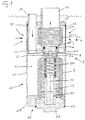
- FIG. 3 shows a longitudinal sectional view through a preferred Embodiment of the jack according to the invention.
- Functionally identical parts As in FIGS. 1 and 2, the same reference numerals are used in FIG. 3.
- the jack shown in FIG. 3 has a generally tubular housing 20 on, with a cylindrical jacket 21 which at one, in Fig. 3 lower end, is closed by a bottom 22 and on its other, in Fig. 3rd upper end, is closed by a cover 23.
- the inside of the tubular housing 20 is axially through a partition 24 in a sub-chamber 24 with a larger volume and a sub-chamber 26 with a smaller volume divided.
- the bottom 22 of the housing 20 is in the illustrated embodiment formed in two parts and comprises a ring 27, the outer periphery of which Corresponds to the outer circumference of the jacket 21, and its eccentric inner circumference has an internal thread, into which a plug 28 with an external thread is screwed in.
- a ring 27 Corresponds to the outer circumference of the jacket 21, and its eccentric inner circumference has an internal thread, into which a plug 28 with an external thread is screwed in.
- an annular groove is formed on the outer circumference of the sealing plug 28, in which sits an O-ring 29 which is supported on the inner circumference of the ring 27.
- a motive water pipe is connected to an inlet pipe 30 connected, a hole in the cover 23 and a corresponding hole interspersed in the partition 24.
- Inlet pipe 30 tightly connected.
- a tubular valve seat carrier 31 is inserted tightly, one into the smaller one Has partial chamber 26 protruding ring part 4a, which with its cover 23rd facing outside forms a valve seat 4a of the bottom valve 4, the also has a return spring 4c, which is formed as a bellows, with one end of which the valve member 4b is fixedly connected, and the other End is firmly connected to a pipe connection 32, which has a hole in the lid 23, interspersed with this and connected to a not shown Delivery line is connected.
- valve seat 6 is formed in the form of a conical surface, which extends in the direction of the valve seat 4a of the bottom valve 4 tapers and to cooperate with a complementary spherical surface on the valve member 3a of the Shock valve 3 cooperates, also in the form of a circular disc is formed, which is fixed to the one, in Fig. 3 upper end of a bellows 5th is connected, which, as explained below, the pressure accumulator of the Shock lifter forms and with the other end firmly with the inner surface of the Sealing plug 28 is connected in the bottom of the housing 20.
- the valve body 3 a of the jack valve 3 has a central bore that of is penetrated by a cylindrical body 35 which with its bottom valve 4 facing end into the interior enclosed by the valve seat support 31 protrudes, and which is flared at the other end, this flange-like end part for fastening the valve body 3 to the bellows 5.
- a Bracket body for the return spring 3b formed by this spring is embraced. This body as well as the flange end of the cylindrical body 35 and this itself is completely penetrated by a capillary bore their extension takes place in a capillary tube 36, which is in the Bottom region of the holding tube 33 extends.
- the casing of the housing 20 is in the region of the smaller subchamber 26 preferably broken in several places, and in these openings sit metal screens 37 and 38.
- FIG. 3 schematically by a wavy line at the top of the Shown jack, this is under the surface of a water reservoir submerged.
- the pressure in sub-chamber 25 acts when open Shock valve 3 on the interior of the bellows 4c, which is the return spring forms for the bottom valve 4, which is still closed at this time, and that existing conveyor water in this interior, and accelerates it, whereby the pressure continues to drop until it falls below the value at which the return spring 3b presses the valve body 3 again against its valve seat and thereby closes the jack valve, the pressure in the sub-chamber 25 is rebuilt.
- valve seats for the bottom valve 4 and the jack valve 3 is the Closing energy of the respective valve advantageously for opening the respective other valve used.
- This advantage is with conventionally built Shock jacks cannot be achieved because the valve seats of the two in question Valves (the bottom valve is a reset valve!) Separated from each other are designed so that kinetic energy does not pass from one valve to another can be transferred. Rather, the one that is released when it is closed kinetic energy through damping, for example in the sealing rubber of the valve destroyed. Such damping is conventionally also required around the so-called bouncing of the respective valve member on the valve seat prevent. This hopping occurs in those trained according to the invention the valve seat interconnected or formed from the same material Valves on because the kinetic energy from the closing valve in the other valve is initiated in order to trigger or close it support.
- valve member is axially flowed against, and the flow runs radially apart after the flow between the valve member and through the valve seat.
- flow of the according to the invention with common valve seat designed valves between the valve members and the associated seats radially inwards together and then axially away from the respective valve. And that's the only way given a common valve seat.
- Another advantage of Coupling the valve seats of the two valves according to the invention consists in that the distance between the two valves is kept negligibly short can be.
- the jack according to the invention can also be operated as a normal ram. For this it is only necessary to provide an additional spring causes the bottom valve 4 to be open in the rest position.
- the way of working of this modified jack is as follows:
- the production water is due to its natural gradient accelerates, and it passes through the open bottom valve 4 on the Pipe connection 32 into the open until a hydrodynamic vacuum between the Valve member 4b and the valve seat 4a and a dynamic pressure in the bellows 4c Close the bottom valve 4.
- the jack valve 3 opens and the kinetic energy of the pumped water loads the spring accumulator (bellows 5), whereby the jack valve 3 closes again and the process as explained above, starts over.
- the spring accumulator bellows 5 however already loaded (i.e. no pressurized water is used) that excludes Bottom valve 4 not when the water has stopped, but only after the excess energy from the spring accumulator Pumped water has accelerated in reverse or backwards.
- the jack valve 3 After this Closing the jack valve 3 then sucks the pumped water through the bottom valve 4 water until the direction of flow reverses. The means, if no pressurized water is required, the consumption of the Pumped water back to a minimum.
- the purpose of the capillary tube 36 or the capillary opening in the valve member is that the pressure inside the bellows 5 is equal to the middle Pressure in the bellows 4c or in the delivery line is. This ensures that the pressure difference between motive water and production water, at which the The jack valve opens regardless of the delivery head. And that's what it is Load on the external motive water pump always the same regardless of whether the jack is used to remove large amounts of surface water or to pump small amounts of water from a great depth.
Landscapes
- Engineering & Computer Science (AREA)
- Mechanical Engineering (AREA)
- General Engineering & Computer Science (AREA)
- Reciprocating Pumps (AREA)
- Fluid-Pressure Circuits (AREA)
- Details Of Reciprocating Pumps (AREA)
- Glass Compositions (AREA)
- Surgical Instruments (AREA)
- Switches With Compound Operations (AREA)
- Braking Systems And Boosters (AREA)
- Lubrication Of Internal Combustion Engines (AREA)
- Valve Device For Special Equipments (AREA)
- Supply Devices, Intensifiers, Converters, And Telemotors (AREA)
- Pipe Accessories (AREA)
- Vehicle Body Suspensions (AREA)
- Percussive Tools And Related Accessories (AREA)
Claims (9)
- Bélier hydraulique comportant :caractérisé en ce que la soupape de bélier hydraulique (3) est maintenue par une force élastique dans sa position fermée séparant la conduite d'eau motrice de la conduite de transport et en ce qu'il est prévu un accumulateur de pression (5) qui est en relation avec la conduite d'eau motrice avant - dans le sens d'écoulement - la soupape de bélier hydraulique (3), un organe de soupape (4b) de la soupape d'admission (4) étant construit en forme d'anneau, étant mobile axialement et étant assemblé de façon étanche à la conduite de transport, la section transversale active de cet assemblage étant plus grande que la section transversale d'un siège de soupape (4a) de la soupape d'admission (4) et le siège de soupape (6) de la soupape de bélier hydraulique (3) et le siège de soupape (4a) de la soupape d'admission (4) étant couplés de façon mécanique pour la transmission d'énergie cinétique.une conduite d'eau motrice (en 30) alimentée en eau motrice,une conduite de transport (en 32) qui peut être mise en relation avec de l'eau de transport par l'intermédiaire d'une soupape d'admission (4),une soupape de bélier hydraulique (3) qui est raccordée à la conduite d'eau motrice (1) et à la conduite de transport (2),dans lequel, lorsque la soupape de bélier hydraulique (3) est ouverte, l'eau motrice coule dans la conduite de transport et, après que la soupape de bélier hydraulique a été fermée, la colonne d'eau coulant dans la conduite de transport aspire de l'eau de transport par l'intermédiaire de la soupape d'admission (4),
- Bélier hydraulique selon la revendication 1,
caractérisé en ce que la soupape de bélier hydraulique (3) et la soupape d'admission (4) sont agencées globalement coaxiales avec leurs sièges de soupapes contigus. - Bélier hydraulique selon la revendication 2,
caractérisé en ce que les deux sièges de soupapes (4a, 6) sont formés aux extrémités opposées d'un support de siège de soupape (24). - Bélier hydraulique selon l'une des revendications 1 à 3, caractérisé en ce que l'accumulateur de pression (5) comporte un soufflet qui est appuyé à une extrémité dans une chambre partielle (25) d'un carter en deux parties, qui est soumis de l'extérieur à l'eau motrice conduite par l'intermédiaire de la conduite d'eau motrice (30) dans cette chambre partielle (25) et qui porte à l'autre extrémité l'organe de soupape (3a) de la soupape de bélier hydraulique (3) dont le siège de soupape (6) repose dans une paroi séparatrice (24) divisant le carter (20) et est assemblé au siège de soupape (4a) de la soupape d'admission (4) qui est agencée dans l'autre chambre partielle qui communique avec l'eau de transport.
- Bélier hydraulique selon la revendication 4,
caractérisé en ce que le soufflet (5) sert comme élément élastique à volume variable de l'accumulateur de pression sans modifier sa dimension axiale pour l'accumulation de la pression. - Bélier hydraulique selon la revendication 4,
caractérisé en ce qu'un ressort de rappel (3b) pour la soupape de bélier hydraulique (3) est agencé à l'intérieur du soufflet accumulateur de pression (5), s'étend de manière coaxiale à celui-ci et s'appuie avec une extrémité au côté intérieur de l'organe de soupape (6) de la soupape de bélier hydraulique (3) et avec son autre extrémité au carter (2). - Bélier hydraulique selon la revendication 4 ou 5, caractérisé en ce que le siège de soupape (6) de la soupape de bélier hydraulique (3) est traversé par un trou capillaire qui relie l'intérieur du soufflet accumulateur de pression (5) à l'espace entre le siège de soupape (4a) de la soupape d'admission (4) et le siège de soupape (6) de la soupape de bélier hydraulique (3).
- Bélier hydraulique selon la revendication 6,
caractérisé en ce qu'il est raccordé au trou capillaire un tuyau capillaire (36) qui s'étend jusque dans la zone du fond du soufflet accumulateur de pression (5). - Bélier hydraulique selon l'une des revendications 4 à 7, caractérisé en ce que la soupape d'admission (4) comporte un soufflet (4c) qui porte à une extrémité le siège de soupape (4a) de la soupape d'admission (4) et qui s'appuie avec son autre extrémité au carter (20) de telle sorte que cet organe de soupape (4b) est poussé en position fermée contre son siège de soupape (4a).
Priority Applications (14)
| Application Number | Priority Date | Filing Date | Title |
|---|---|---|---|
| AU16354/97A AU708806B2 (en) | 1996-04-19 | 1997-03-14 | Hydraulic ram pump |
| CN97192909A CN1081758C (zh) | 1996-04-19 | 1997-04-16 | 液压水锤泵 |
| US09/142,312 US6234764B1 (en) | 1996-04-19 | 1997-04-16 | Hydraulic ram pump |
| CA002249263A CA2249263C (fr) | 1996-04-19 | 1997-04-16 | Pompe hydraulique de type belier |
| AU26380/97A AU2638097A (en) | 1996-04-19 | 1997-04-16 | Hydraulic ram pump |
| KR10-1998-0708318A KR100383489B1 (ko) | 1996-04-19 | 1997-04-16 | 수압 램 펌프 |
| RU98120702A RU2159361C2 (ru) | 1996-12-04 | 1997-04-16 | Гидравлический плунжерный насос |
| NZ331397A NZ331397A (en) | 1996-04-19 | 1997-04-16 | Hydraulic ram pump with closing energy of one valve used to open another valve |
| PCT/EP1997/001908 WO1997040277A1 (fr) | 1996-04-19 | 1997-04-16 | Pompe hydraulique de type belier |
| CZ983322A CZ332298A3 (cs) | 1996-04-19 | 1997-04-16 | Hydraulické plunžrové čerpadlo |
| JP53770097A JP3853847B2 (ja) | 1996-04-19 | 1997-04-16 | 水圧ラムポンプ |
| PL97329346A PL182664B1 (pl) | 1996-04-19 | 1997-04-16 | Pompa nurnikowa hydrauliczna |
| IL12589397A IL125893A (en) | 1996-04-19 | 1997-04-16 | Hydraulic ram pump |
| IDP971312A ID16633A (id) | 1996-04-19 | 1997-04-21 | Pompa pelantak hidrolik |
Applications Claiming Priority (2)
| Application Number | Priority Date | Filing Date | Title |
|---|---|---|---|
| DE19615689 | 1996-04-19 | ||
| DE19615689A DE19615689A1 (de) | 1996-04-19 | 1996-04-19 | Hydraulische Saugwidder-Trägheitspumpe |
Publications (2)
| Publication Number | Publication Date |
|---|---|
| EP0802328A1 EP0802328A1 (fr) | 1997-10-22 |
| EP0802328B1 true EP0802328B1 (fr) | 2001-07-18 |
Family
ID=7791876
Family Applications (1)
| Application Number | Title | Priority Date | Filing Date |
|---|---|---|---|
| EP96119475A Expired - Lifetime EP0802328B1 (fr) | 1996-04-19 | 1996-12-04 | Bélier-aspirateur |
Country Status (7)
| Country | Link |
|---|---|
| EP (1) | EP0802328B1 (fr) |
| KR (1) | KR100383489B1 (fr) |
| AT (1) | ATE203307T1 (fr) |
| BR (1) | BR9708769A (fr) |
| DE (2) | DE19615689A1 (fr) |
| ES (1) | ES2160758T3 (fr) |
| GR (1) | GR3036876T3 (fr) |
Families Citing this family (2)
| Publication number | Priority date | Publication date | Assignee | Title |
|---|---|---|---|---|
| KR100412134B1 (ko) * | 2001-06-27 | 2003-12-31 | 주식회사 하이닉스반도체 | 넓은 범위의 전원전압에서 동작하는 데이터 출력 버퍼 및이를 이용하는 반도체 메모리 장치 |
| GB202105296D0 (en) * | 2021-04-14 | 2021-05-26 | Thermofluidics Ltd | Inlet end assemblies for hydraulic ram pumps |
Family Cites Families (3)
| Publication number | Priority date | Publication date | Assignee | Title |
|---|---|---|---|---|
| DE628113C (de) * | 1934-10-31 | 1936-03-30 | Harry Sauveur Dipl Ing | Fluessigkeitspumpe |
| DE804288C (de) * | 1949-06-28 | 1951-04-19 | Wilhelm Raub | Unterbrecherpumpe |
| CH666942A5 (de) * | 1985-09-10 | 1988-08-31 | Cyphelly Ivan J | Saugwidder-pumpeinrichtung fuer einen schacht. |
-
1996
- 1996-04-19 DE DE19615689A patent/DE19615689A1/de not_active Withdrawn
- 1996-12-04 AT AT96119475T patent/ATE203307T1/de not_active IP Right Cessation
- 1996-12-04 DE DE59607317T patent/DE59607317D1/de not_active Expired - Fee Related
- 1996-12-04 EP EP96119475A patent/EP0802328B1/fr not_active Expired - Lifetime
- 1996-12-04 ES ES96119475T patent/ES2160758T3/es not_active Expired - Lifetime
-
1997
- 1997-04-16 BR BR9708769A patent/BR9708769A/pt active Search and Examination
- 1997-04-16 KR KR10-1998-0708318A patent/KR100383489B1/ko not_active Expired - Fee Related
-
2001
- 2001-10-11 GR GR20010401739T patent/GR3036876T3/el not_active IP Right Cessation
Also Published As
| Publication number | Publication date |
|---|---|
| GR3036876T3 (en) | 2002-01-31 |
| ES2160758T3 (es) | 2001-11-16 |
| DE19615689A1 (de) | 1997-10-23 |
| EP0802328A1 (fr) | 1997-10-22 |
| KR20000005524A (ko) | 2000-01-25 |
| DE59607317D1 (de) | 2001-08-23 |
| KR100383489B1 (ko) | 2003-06-18 |
| ATE203307T1 (de) | 2001-08-15 |
| BR9708769A (pt) | 1999-08-03 |
Similar Documents
| Publication | Publication Date | Title |
|---|---|---|
| DE4291026C2 (de) | Schwingungsdämpfer für ein gepumptes Flüssigkeitssystem | |
| EP2294316B1 (fr) | Pompe à piston d'un système hydraulique de freinage de véhicule | |
| DE1117412B (de) | Hydropneumatische Abfederung, insbesondere fuer Kraftfahrzeuge | |
| DE2162320A1 (fr) | ||
| EP0594537A1 (fr) | Convertisseur de l'énergie des vagues | |
| DE3900899A1 (de) | Druckspeicher | |
| DE7111463U (de) | Schallimpulserzeuger | |
| DE3130830A1 (de) | Federelement und dessen verwendung | |
| DE1043102B (de) | Hydropneumatische Abfederung, insbesondere fuer Kraftfahrzeuge | |
| DE1528439C3 (de) | Druckspeicher zur Aufrechterhaltung eines Druckarbeitsbereiches in einem hydraulischen System | |
| DE19857595A1 (de) | Selbstpumpendes hydropneumatisches Federbein mit innerer Niveauregelung | |
| DE1294234B (de) | Aus einem Teleskop-Fluessigkeitsschwingungsdaempfer und diesen umgebender Schraubenfeder gebildetes Federbein fuer Kraftfahrzeuge | |
| DE1936858A1 (de) | Stossdaempfer | |
| DE1755237B1 (de) | Selbstpumpendes hydropneumatisches Federbein mit innerer Niveauregelung fuer Fahrzeuge | |
| DE19602166B4 (de) | Selbstpumpender hydropneumatischer Schwingungsdämpfer mit Einrichtungen zur variablen Steuerung der Dämpfungskraft | |
| DE3443768A1 (de) | Schlauch-kolbenpumpe | |
| DE2419010B2 (de) | Ventilanordnung fuer eine fahrzeug- hydraulikanlage | |
| DD271063A5 (de) | Druckluftpatrone | |
| EP0648315A1 (fr) | Appareil de nettoyage sous haute pression. | |
| DE2715424A1 (de) | Ventil fuer einen druckspeicher | |
| DE2322354A1 (de) | Arbeitszylinder, insbesondere hydraulikzylinder, mit einer daempfungseinrichtung fuer das ende des arbeitshubes des kolbens | |
| DE1114684B (de) | Federbelastetes UEberdruckventil fuer Fluessigkeiten, vorzugsweise zur Verwendung bei Teleskop-Grubenstempeln | |
| DE2213104A1 (de) | Ventil für eine Flüssigkeitspumpe | |
| DE19926226C2 (de) | Stoßventilanordnung für einen hydraulischen Widder | |
| EP0802328A1 (fr) | Bélier-aspirateur |
Legal Events
| Date | Code | Title | Description |
|---|---|---|---|
| PUAI | Public reference made under article 153(3) epc to a published international application that has entered the european phase |
Free format text: ORIGINAL CODE: 0009012 |
|
| AK | Designated contracting states |
Kind code of ref document: A1 Designated state(s): AT CH DE ES FR GB GR IT LI |
|
| 17P | Request for examination filed |
Effective date: 19980324 |
|
| 17Q | First examination report despatched |
Effective date: 19990914 |
|
| GRAG | Despatch of communication of intention to grant |
Free format text: ORIGINAL CODE: EPIDOS AGRA |
|
| GRAG | Despatch of communication of intention to grant |
Free format text: ORIGINAL CODE: EPIDOS AGRA |
|
| GRAH | Despatch of communication of intention to grant a patent |
Free format text: ORIGINAL CODE: EPIDOS IGRA |
|
| RAP1 | Party data changed (applicant data changed or rights of an application transferred) |
Owner name: SIEBHOLZ, DIETMAR |
|
| RIN1 | Information on inventor provided before grant (corrected) |
Inventor name: OBERMOSER, KARL |
|
| GRAH | Despatch of communication of intention to grant a patent |
Free format text: ORIGINAL CODE: EPIDOS IGRA |
|
| GRAA | (expected) grant |
Free format text: ORIGINAL CODE: 0009210 |
|
| AK | Designated contracting states |
Kind code of ref document: B1 Designated state(s): AT CH DE ES FR GB GR IT LI |
|
| REF | Corresponds to: |
Ref document number: 203307 Country of ref document: AT Date of ref document: 20010815 Kind code of ref document: T |
|
| ITF | It: translation for a ep patent filed | ||
| REG | Reference to a national code |
Ref country code: CH Ref legal event code: EP |
|
| ET | Fr: translation filed | ||
| REG | Reference to a national code |
Ref country code: CH Ref legal event code: NV Representative=s name: BUECHEL, KAMINSKI & PARTNER PATENTANWAELTE ESTABLI |
|
| REF | Corresponds to: |
Ref document number: 59607317 Country of ref document: DE Date of ref document: 20010823 |
|
| GBT | Gb: translation of ep patent filed (gb section 77(6)(a)/1977) |
Effective date: 20011018 |
|
| REG | Reference to a national code |
Ref country code: ES Ref legal event code: FG2A Ref document number: 2160758 Country of ref document: ES Kind code of ref document: T3 |
|
| REG | Reference to a national code |
Ref country code: GB Ref legal event code: IF02 |
|
| REG | Reference to a national code |
Ref country code: GR Ref legal event code: EP Ref document number: 20010401739 Country of ref document: GR |
|
| PLBE | No opposition filed within time limit |
Free format text: ORIGINAL CODE: 0009261 |
|
| STAA | Information on the status of an ep patent application or granted ep patent |
Free format text: STATUS: NO OPPOSITION FILED WITHIN TIME LIMIT |
|
| 26N | No opposition filed | ||
| PGFP | Annual fee paid to national office [announced via postgrant information from national office to epo] |
Ref country code: GB Payment date: 20051220 Year of fee payment: 10 |
|
| PGFP | Annual fee paid to national office [announced via postgrant information from national office to epo] |
Ref country code: FR Payment date: 20051229 Year of fee payment: 10 |
|
| PGFP | Annual fee paid to national office [announced via postgrant information from national office to epo] |
Ref country code: DE Payment date: 20051230 Year of fee payment: 10 |
|
| PGFP | Annual fee paid to national office [announced via postgrant information from national office to epo] |
Ref country code: AT Payment date: 20060123 Year of fee payment: 10 |
|
| PGFP | Annual fee paid to national office [announced via postgrant information from national office to epo] |
Ref country code: GR Payment date: 20060124 Year of fee payment: 10 Ref country code: CH Payment date: 20060124 Year of fee payment: 10 |
|
| PGFP | Annual fee paid to national office [announced via postgrant information from national office to epo] |
Ref country code: ES Payment date: 20060127 Year of fee payment: 10 |
|
| PG25 | Lapsed in a contracting state [announced via postgrant information from national office to epo] |
Ref country code: LI Free format text: LAPSE BECAUSE OF NON-PAYMENT OF DUE FEES Effective date: 20061231 Ref country code: CH Free format text: LAPSE BECAUSE OF NON-PAYMENT OF DUE FEES Effective date: 20061231 |
|
| PGFP | Annual fee paid to national office [announced via postgrant information from national office to epo] |
Ref country code: IT Payment date: 20061231 Year of fee payment: 11 |
|
| PG25 | Lapsed in a contracting state [announced via postgrant information from national office to epo] |
Ref country code: DE Free format text: LAPSE BECAUSE OF NON-PAYMENT OF DUE FEES Effective date: 20070703 |
|
| REG | Reference to a national code |
Ref country code: CH Ref legal event code: PL |
|
| GBPC | Gb: european patent ceased through non-payment of renewal fee |
Effective date: 20061204 |
|
| REG | Reference to a national code |
Ref country code: FR Ref legal event code: ST Effective date: 20070831 |
|
| PG25 | Lapsed in a contracting state [announced via postgrant information from national office to epo] |
Ref country code: GB Free format text: LAPSE BECAUSE OF NON-PAYMENT OF DUE FEES Effective date: 20061204 Ref country code: AT Free format text: LAPSE BECAUSE OF NON-PAYMENT OF DUE FEES Effective date: 20061204 |
|
| REG | Reference to a national code |
Ref country code: ES Ref legal event code: FD2A Effective date: 20061205 |
|
| PG25 | Lapsed in a contracting state [announced via postgrant information from national office to epo] |
Ref country code: FR Free format text: LAPSE BECAUSE OF NON-PAYMENT OF DUE FEES Effective date: 20070102 Ref country code: ES Free format text: LAPSE BECAUSE OF NON-PAYMENT OF DUE FEES Effective date: 20061205 |
|
| PG25 | Lapsed in a contracting state [announced via postgrant information from national office to epo] |
Ref country code: GR Free format text: LAPSE BECAUSE OF NON-PAYMENT OF DUE FEES Effective date: 20070704 |
|
| PG25 | Lapsed in a contracting state [announced via postgrant information from national office to epo] |
Ref country code: IT Free format text: LAPSE BECAUSE OF NON-PAYMENT OF DUE FEES Effective date: 20071204 |