EP0802329A2 - Dispositif pour l'aération d'un réservoir - Google Patents
Dispositif pour l'aération d'un réservoir Download PDFInfo
- Publication number
- EP0802329A2 EP0802329A2 EP97105577A EP97105577A EP0802329A2 EP 0802329 A2 EP0802329 A2 EP 0802329A2 EP 97105577 A EP97105577 A EP 97105577A EP 97105577 A EP97105577 A EP 97105577A EP 0802329 A2 EP0802329 A2 EP 0802329A2
- Authority
- EP
- European Patent Office
- Prior art keywords
- storage tank
- inlet
- air
- compressed air
- pressure regulator
- Prior art date
- Legal status (The legal status is an assumption and is not a legal conclusion. Google has not performed a legal analysis and makes no representation as to the accuracy of the status listed.)
- Granted
Links
Images

Classifications
-
- F—MECHANICAL ENGINEERING; LIGHTING; HEATING; WEAPONS; BLASTING
- F15—FLUID-PRESSURE ACTUATORS; HYDRAULICS OR PNEUMATICS IN GENERAL
- F15B—SYSTEMS ACTING BY MEANS OF FLUIDS IN GENERAL; FLUID-PRESSURE ACTUATORS, e.g. SERVOMOTORS; DETAILS OF FLUID-PRESSURE SYSTEMS, NOT OTHERWISE PROVIDED FOR
- F15B1/00—Installations or systems with accumulators; Supply reservoir or sump assemblies
- F15B1/26—Supply reservoir or sump assemblies
- F15B1/265—Supply reservoir or sump assemblies with pressurised main reservoir
-
- F—MECHANICAL ENGINEERING; LIGHTING; HEATING; WEAPONS; BLASTING
- F15—FLUID-PRESSURE ACTUATORS; HYDRAULICS OR PNEUMATICS IN GENERAL
- F15B—SYSTEMS ACTING BY MEANS OF FLUIDS IN GENERAL; FLUID-PRESSURE ACTUATORS, e.g. SERVOMOTORS; DETAILS OF FLUID-PRESSURE SYSTEMS, NOT OTHERWISE PROVIDED FOR
- F15B21/00—Common features of fluid actuator systems; Fluid-pressure actuator systems or details thereof, not covered by any other group of this subclass
- F15B21/04—Special measures taken in connection with the properties of the fluid
- F15B21/044—Removal or measurement of undissolved gas, e.g. de-aeration, venting or bleeding
Definitions
- the invention relates to a device for venting a storage tank of a system operating with hydraulic fluid, in which changes in the level of the liquid occur in the storage tank, the latter having an inlet for dried air above the level of the liquid.
- the object of the invention is to provide dried air without using a special air dryer.
- the air entering the storage tank is dried in that the moisture is precipitated anyway when compressed air is generated.
- the pressure regulator By means of the pressure regulator, the compressed air is expanded to approximately atmospheric pressure and in this state is fed to the storage tank, in which a slight excess pressure can form.
- the inflow of relaxed air is therefore limited to the amount of liquid withdrawn from the storage tank.
- the compressed air source is designed as a branch from a compressed air generation system required outside the system. This can be particularly useful if the system is located in a device, for example a mobile construction machine with a compressed air braking device, in which a compressed air generation system must be present anyway.
- the inlet can also serve as an outlet for excess air in the storage tank. When liquid flows back into the storage tank, the excess air can escape in this way.
- an aerosol separator is inserted between the pressure regulator and the inlet.
- the aerosol separator can also be connected downstream of the outlet in order to filter out contaminants that are entrained in the liquid.
- a compact design of the device results from the fact that the pressure regulator, a compressed air inlet connection connected to the compressed air source, a connection serving as the inlet and outlet of the storage tank and an exhaust air outlet opening with an upstream pressure relief valve are combined in a unit which can be mounted on the storage tank.
- the device can thus be installed fully assembled in the system.
- a first check valve connected between the pressure regulator and the connection to the storage tank can also be provided in the structural unit, with the inflow of air bypassing the aerosol separator, and / or one between the connection to the storage tank and another Exhaust air outlet switched second check valve may be provided, in the open position of which outflowing air bypasses the aerosol separator.
- Another possibility using compressed air from a compressed air source in such storage tanks to avoid the formation of condensed water and the consequent premature aging of the liquid, corrosion, increased wear and, at appropriate temperatures, icing is by means of a compressed air operated ejector in the storage tank above it Outlet to a negative pressure generate, whereby air is sucked out of the storage tank, and connected in parallel to vent the inlet of the storage tank via a pressure regulator from the compressed air source.
- the negative pressure in the storage tank causes a lowering of the water vapor partial pressure and thus outgassing of the liquid.
- the air sucked out of the storage tank can contain aerosols which are separated out in an aerosol separator connected downstream of the ejector, which is followed by an exhaust air outlet opening.
- the storage tank is also ventilated via the pressure regulator via a vacuum relief valve, which prevents excessive vacuum from developing in the storage tank.
- a pressure relief valve leading to the exhaust air outlet can also be connected directly or indirectly to the storage tank, which, if a large amount of liquid suddenly flows back, allows air to flow out of the storage tank and thus prevents an undesirable increase in the pressure in the storage tank.
- a connection from the compressed air source, the pressure regulator, the vacuum relief valve, the ejector, the aerosol separator and the pressure relief valve can be combined to form one structural unit.
- a pressure regulator 2 is connected downstream of a compressed air source 1.
- an aerosol separator 3 which is connected via a line connection to an inlet 4 of a storage tank 5.
- the inlet 4 serves at the same time as the outlet of the storage tank 5, which is connected via the line connection and the aerosol separator 3 to a pressure relief valve 6, to which an exhaust air outlet opening 7 connects. Liquid is withdrawn from the storage tank 5 and liquid flows back into it, as indicated by arrows.
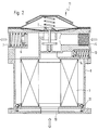
- the assembly 11 shown in FIG. 2 has in a housing 8 a compressed air inlet connection 9 which is connected to the compressed air source 1 and which is connected via the pressure regulator 2 to a space in the housing 8 enclosing the aerosol separator 3.
- the space formed within the aerosol separator 3 opens at the bottom into a connection 10 which serves as an inlet 4 to the storage tank 5 and also as an outlet from the storage tank 5.
- the space enclosing the aerosol separator 3 in the housing 8 is connected to the exhaust air outlet opening 7 via the pressure relief valve 6.
- a first check valve 12 is connected between the space enclosing the aerosol separator 3 in the housing 8 and the connection 10, and air flowing in bypasses the aerosol separator 3 when it is in the open position.
- a second check valve 14 is connected, in the open position of which air flowing out bypasses the aerosol separator 3.
- a compressed air source 21 is followed by a pressure regulator 22.
- This is followed by an ejector 23, which in turn is followed by an aerosol separator 24 and finally by an exhaust air outlet opening 27.
- a line connection branches off, which leads via a vacuum relief valve 31 to an inlet 25 of a storage tank 26.
- a pressure relief valve 28 is connected, which leads to an exhaust air outlet 29.
- an outlet 30 of the storage tank 26 is connected to the ejector 23, namely at its suction connection, via a further line connection. Liquid is withdrawn from the storage tank 26 and liquid flows back into it, as indicated by arrows.
Landscapes
- Engineering & Computer Science (AREA)
- Physics & Mathematics (AREA)
- Fluid Mechanics (AREA)
- Mechanical Engineering (AREA)
- General Engineering & Computer Science (AREA)
- Chemical & Material Sciences (AREA)
- Analytical Chemistry (AREA)
- Jet Pumps And Other Pumps (AREA)
- Respiratory Apparatuses And Protective Means (AREA)
- Valves And Accessory Devices For Braking Systems (AREA)
Applications Claiming Priority (2)
| Application Number | Priority Date | Filing Date | Title |
|---|---|---|---|
| DE19615475 | 1996-04-19 | ||
| DE19615475A DE19615475A1 (de) | 1996-04-19 | 1996-04-19 | Einrichtung zur Belüftung eines Vorratstanks |
Publications (3)
| Publication Number | Publication Date |
|---|---|
| EP0802329A2 true EP0802329A2 (fr) | 1997-10-22 |
| EP0802329A3 EP0802329A3 (fr) | 1998-02-11 |
| EP0802329B1 EP0802329B1 (fr) | 2001-08-01 |
Family
ID=7791734
Family Applications (1)
| Application Number | Title | Priority Date | Filing Date |
|---|---|---|---|
| EP97105577A Expired - Lifetime EP0802329B1 (fr) | 1996-04-19 | 1997-04-04 | Dispositif pour l'aération d'un réservoir |
Country Status (2)
| Country | Link |
|---|---|
| EP (1) | EP0802329B1 (fr) |
| DE (2) | DE19615475A1 (fr) |
Cited By (3)
| Publication number | Priority date | Publication date | Assignee | Title |
|---|---|---|---|---|
| CN102357974A (zh) * | 2011-09-28 | 2012-02-22 | 无锡锦和科技有限公司 | 自封式大通流量排气罐 |
| WO2016097512A1 (fr) * | 2014-12-17 | 2016-06-23 | Technoboost | Circuit hydraulique comprenant un reservoir tres basse pression mis en depression |
| CN120887127A (zh) * | 2025-09-30 | 2025-11-04 | 苏州杜尔气体化工装备有限公司 | 一种具有过滤干燥功能的储罐吸阀补气系统及其储罐 |
Families Citing this family (3)
| Publication number | Priority date | Publication date | Assignee | Title |
|---|---|---|---|---|
| DE10002118A1 (de) * | 2000-01-20 | 2001-07-26 | Mann & Hummel Filter | Ausgleichsbehälter eines Hydrauliksystems |
| RU2241865C2 (ru) * | 2002-12-31 | 2004-12-10 | Открытое акционерное общество "Красноярский проектно-конструкторский технологический институт комбайностроения" | Гидробак |
| DE102007052023A1 (de) * | 2007-10-31 | 2009-05-07 | Trw Automotive Gmbh | Hydraulikfluidspeicher sowie hydraulisches Servolenksystem mit einem solchen Hydraulikfluidspeicher |
Family Cites Families (8)
| Publication number | Priority date | Publication date | Assignee | Title |
|---|---|---|---|---|
| US2208451A (en) * | 1938-11-18 | 1940-07-16 | Gen Electric | Hydraulic mechanism |
| GB580604A (en) * | 1944-06-19 | 1946-09-13 | Automotive Prod Co Ltd | Improvements in or relating to liquid circulating systems |
| DE2618372A1 (de) * | 1976-04-27 | 1977-11-17 | Franz Walter | Kontinuierlich arbeitender druckmittelwandler |
| DE2650802C2 (de) * | 1976-11-03 | 1981-10-08 | Borsig Gmbh, 1000 Berlin | Gas-Öl-Antrieb |
| US4827719A (en) * | 1983-11-14 | 1989-05-09 | Paoluccio John A | Closed hydraulic system with drying means |
| DE8511057U1 (de) * | 1985-04-16 | 1985-10-03 | Bodendorfer, Gerhard, 7505 Ettlingen | Druckhaltekopf |
| HU201705B (en) * | 1988-11-04 | 1990-12-28 | Autoipari Kutato Fejlesztoe | Vehicle air dryer with control gear particularly for pressure air systems |
| DE4031494C2 (de) * | 1990-10-05 | 1994-07-21 | Bundesrep Deutschland | Hydraulikölbehälter |
-
1996
- 1996-04-19 DE DE19615475A patent/DE19615475A1/de not_active Withdrawn
-
1997
- 1997-04-04 EP EP97105577A patent/EP0802329B1/fr not_active Expired - Lifetime
- 1997-04-04 DE DE59704163T patent/DE59704163D1/de not_active Expired - Lifetime
Cited By (7)
| Publication number | Priority date | Publication date | Assignee | Title |
|---|---|---|---|---|
| CN102357974A (zh) * | 2011-09-28 | 2012-02-22 | 无锡锦和科技有限公司 | 自封式大通流量排气罐 |
| CN102357974B (zh) * | 2011-09-28 | 2016-02-03 | 无锡锦和科技有限公司 | 自封式大通流量排气罐 |
| WO2016097512A1 (fr) * | 2014-12-17 | 2016-06-23 | Technoboost | Circuit hydraulique comprenant un reservoir tres basse pression mis en depression |
| FR3030650A1 (fr) * | 2014-12-17 | 2016-06-24 | Technoboost | Circuit hydraulique comprenant un reservoir tres basse pression mis en depression |
| CN107107727A (zh) * | 2014-12-17 | 2017-08-29 | 技术推进公司 | 包括处于负压的极低压容器的液压回路 |
| CN107107727B (zh) * | 2014-12-17 | 2020-08-07 | 技术推进公司 | 包括处于负压的极低压容器的液压回路 |
| CN120887127A (zh) * | 2025-09-30 | 2025-11-04 | 苏州杜尔气体化工装备有限公司 | 一种具有过滤干燥功能的储罐吸阀补气系统及其储罐 |
Also Published As
| Publication number | Publication date |
|---|---|
| EP0802329B1 (fr) | 2001-08-01 |
| EP0802329A3 (fr) | 1998-02-11 |
| DE59704163D1 (de) | 2001-09-06 |
| DE19615475A1 (de) | 1997-10-23 |
Similar Documents
| Publication | Publication Date | Title |
|---|---|---|
| DE3882782T2 (de) | Mehrfachölfilter für Verbrennungskraftmaschinen mit Anzeige der Verschmutzung der Filteroberfläche. | |
| DE4237784C2 (de) | Kraftstoff-Zuführeinrichtung für eine Brennkraftmaschine | |
| DE3106980A1 (de) | Verdichter | |
| DE102008023594A1 (de) | Kompressoreinheit | |
| DE3026203A1 (de) | Oelgekuehlter kompressor | |
| DE3032243C2 (de) | Druckregelventil für den Einbau in eine Entlüftungsleitung einer Brennkraftmaschine | |
| DE102020214814A1 (de) | Brennstoffzellensystem | |
| DE10048439C2 (de) | Dampfturbinenanlage und Verfahren zum Betreiben einer Dampfturbinenanlage | |
| DE102019003386A1 (de) | Vorrichtung zur Rezirkulation von Abgas | |
| EP0802329A2 (fr) | Dispositif pour l'aération d'un réservoir | |
| DE3133452A1 (de) | Drucklufttrockner | |
| DE2426378A1 (de) | Ventilplatte fuer kolbenkompressoren | |
| EP0486726B1 (fr) | Pompe à anneau liquide | |
| DE102021109017A1 (de) | Wasserstoffgaszufuhrvorrichtung | |
| DE102018200681A1 (de) | Brennstoffzellensystem mit einer dem Verdichter zugeordneten Mitteldruckentnahme sowie Verwendung eines derartigen Brennstoffzellensystems | |
| WO2001044712A1 (fr) | Procede et dispositif pour evacuer un condensat | |
| DE112018000942T5 (de) | Brennstoffzellenstapel unde Fahrzeug mit einem Brennstoffzellenstapel | |
| DE2855608A1 (de) | Doppelt wirkende vakuumpumpe | |
| DE19600377B4 (de) | Druckgasanlage mit einem Gastrockner | |
| DE3213236A1 (de) | Einrichtung mit einem lufttrockner fuer druckluftanlagen | |
| DE19626956B4 (de) | Gastrockner mit einer Auslaßkammer | |
| DE102022204160A1 (de) | Verfahren zum Betreiben eines mehrstufigen Luftverdichtungssystems, mehrstufiges Luftverdichtungssystem sowie Brennstoffzellensystem | |
| DE102020200611A1 (de) | Brennstoffzellensystem | |
| DE3114522A1 (de) | Turboverdichteranlage | |
| DE2843170A1 (de) | Anordnung in einem kompressor zur draenierung von fluessigkeit |
Legal Events
| Date | Code | Title | Description |
|---|---|---|---|
| PUAI | Public reference made under article 153(3) epc to a published international application that has entered the european phase |
Free format text: ORIGINAL CODE: 0009012 |
|
| AK | Designated contracting states |
Kind code of ref document: A2 Designated state(s): CH DE FR GB IT LI SE |
|
| PUAL | Search report despatched |
Free format text: ORIGINAL CODE: 0009013 |
|
| AK | Designated contracting states |
Kind code of ref document: A3 Designated state(s): CH DE FR GB IT LI SE |
|
| RHK1 | Main classification (correction) |
Ipc: F15B 1/26 |
|
| RTI1 | Title (correction) | ||
| 17P | Request for examination filed |
Effective date: 19980721 |
|
| RAP1 | Party data changed (applicant data changed or rights of an application transferred) |
Owner name: MAHLE FILTERSYSTEME GMBH |
|
| 17Q | First examination report despatched |
Effective date: 20000218 |
|
| GRAG | Despatch of communication of intention to grant |
Free format text: ORIGINAL CODE: EPIDOS AGRA |
|
| GRAG | Despatch of communication of intention to grant |
Free format text: ORIGINAL CODE: EPIDOS AGRA |
|
| GRAH | Despatch of communication of intention to grant a patent |
Free format text: ORIGINAL CODE: EPIDOS IGRA |
|
| GRAH | Despatch of communication of intention to grant a patent |
Free format text: ORIGINAL CODE: EPIDOS IGRA |
|
| GRAA | (expected) grant |
Free format text: ORIGINAL CODE: 0009210 |
|
| AK | Designated contracting states |
Kind code of ref document: B1 Designated state(s): CH DE FR GB IT LI SE |
|
| PG25 | Lapsed in a contracting state [announced via postgrant information from national office to epo] |
Ref country code: IT Free format text: LAPSE BECAUSE OF FAILURE TO SUBMIT A TRANSLATION OF THE DESCRIPTION OR TO PAY THE FEE WITHIN THE PRE;WARNING: LAPSES OF ITALIAN PATENTS WITH EFFECTIVE DATE BEFORE 2007 MAY HAVE OCCURRED AT ANY TIME BEFORE 2007. THE CORRECT EFFECTIVE DATE MAY BE DIFFERENT FROM THE ONE RECORDED.SCRIBED TIME-LIMIT Effective date: 20010801 |
|
| REG | Reference to a national code |
Ref country code: CH Ref legal event code: EP |
|
| REF | Corresponds to: |
Ref document number: 59704163 Country of ref document: DE Date of ref document: 20010906 |
|
| GBT | Gb: translation of ep patent filed (gb section 77(6)(a)/1977) |
Effective date: 20010917 |
|
| ET | Fr: translation filed | ||
| REG | Reference to a national code |
Ref country code: GB Ref legal event code: IF02 |
|
| PLBE | No opposition filed within time limit |
Free format text: ORIGINAL CODE: 0009261 |
|
| STAA | Information on the status of an ep patent application or granted ep patent |
Free format text: STATUS: NO OPPOSITION FILED WITHIN TIME LIMIT |
|
| 26N | No opposition filed | ||
| PGFP | Annual fee paid to national office [announced via postgrant information from national office to epo] |
Ref country code: CH Payment date: 20080428 Year of fee payment: 12 |
|
| PGFP | Annual fee paid to national office [announced via postgrant information from national office to epo] |
Ref country code: SE Payment date: 20080422 Year of fee payment: 12 |
|
| PGFP | Annual fee paid to national office [announced via postgrant information from national office to epo] |
Ref country code: GB Payment date: 20080422 Year of fee payment: 12 |
|
| REG | Reference to a national code |
Ref country code: CH Ref legal event code: PL |
|
| EUG | Se: european patent has lapsed | ||
| GBPC | Gb: european patent ceased through non-payment of renewal fee |
Effective date: 20090404 |
|
| REG | Reference to a national code |
Ref country code: FR Ref legal event code: ST Effective date: 20091231 |
|
| PG25 | Lapsed in a contracting state [announced via postgrant information from national office to epo] |
Ref country code: LI Free format text: LAPSE BECAUSE OF NON-PAYMENT OF DUE FEES Effective date: 20090430 Ref country code: CH Free format text: LAPSE BECAUSE OF NON-PAYMENT OF DUE FEES Effective date: 20090430 |
|
| PG25 | Lapsed in a contracting state [announced via postgrant information from national office to epo] |
Ref country code: GB Free format text: LAPSE BECAUSE OF NON-PAYMENT OF DUE FEES Effective date: 20090404 Ref country code: FR Free format text: LAPSE BECAUSE OF NON-PAYMENT OF DUE FEES Effective date: 20091222 |
|
| PGFP | Annual fee paid to national office [announced via postgrant information from national office to epo] |
Ref country code: FR Payment date: 20080422 Year of fee payment: 12 |
|
| PGFP | Annual fee paid to national office [announced via postgrant information from national office to epo] |
Ref country code: DE Payment date: 20100511 Year of fee payment: 14 |
|
| PG25 | Lapsed in a contracting state [announced via postgrant information from national office to epo] |
Ref country code: SE Free format text: LAPSE BECAUSE OF NON-PAYMENT OF DUE FEES Effective date: 20090405 |
|
| REG | Reference to a national code |
Ref country code: DE Ref legal event code: R119 Ref document number: 59704163 Country of ref document: DE |
|
| REG | Reference to a national code |
Ref country code: DE Ref legal event code: R119 Ref document number: 59704163 Country of ref document: DE |
|
| PG25 | Lapsed in a contracting state [announced via postgrant information from national office to epo] |
Ref country code: DE Free format text: LAPSE BECAUSE OF NON-PAYMENT OF DUE FEES Effective date: 20111031 |