EP0802335A1 - Système de montage, procédé pour son montage et bande profilée pour le système de montage - Google Patents
Système de montage, procédé pour son montage et bande profilée pour le système de montage Download PDFInfo
- Publication number
- EP0802335A1 EP0802335A1 EP97106312A EP97106312A EP0802335A1 EP 0802335 A1 EP0802335 A1 EP 0802335A1 EP 97106312 A EP97106312 A EP 97106312A EP 97106312 A EP97106312 A EP 97106312A EP 0802335 A1 EP0802335 A1 EP 0802335A1
- Authority
- EP
- European Patent Office
- Prior art keywords
- locking device
- tubular element
- tubular
- elements
- actuating end
- Prior art date
- Legal status (The legal status is an assumption and is not a legal conclusion. Google has not performed a legal analysis and makes no representation as to the accuracy of the status listed.)
- Withdrawn
Links
- 238000000034 method Methods 0.000 title claims description 14
- 238000007789 sealing Methods 0.000 claims description 59
- 230000002093 peripheral effect Effects 0.000 claims description 57
- 239000004033 plastic Substances 0.000 claims description 12
- 230000007704 transition Effects 0.000 claims description 10
- 230000008569 process Effects 0.000 claims description 6
- 238000006243 chemical reaction Methods 0.000 claims description 5
- 241000937413 Axia Species 0.000 claims 1
- 239000000428 dust Substances 0.000 abstract 1
- 238000013461 design Methods 0.000 description 39
- 239000000463 material Substances 0.000 description 20
- 238000010276 construction Methods 0.000 description 15
- 238000003780 insertion Methods 0.000 description 13
- 230000037431 insertion Effects 0.000 description 13
- 238000004519 manufacturing process Methods 0.000 description 12
- 230000008901 benefit Effects 0.000 description 9
- 230000005540 biological transmission Effects 0.000 description 7
- 229910000639 Spring steel Inorganic materials 0.000 description 6
- 238000005755 formation reaction Methods 0.000 description 6
- 239000011324 bead Substances 0.000 description 5
- 230000015572 biosynthetic process Effects 0.000 description 5
- 238000009434 installation Methods 0.000 description 5
- 239000002184 metal Substances 0.000 description 5
- 230000004323 axial length Effects 0.000 description 4
- 230000008878 coupling Effects 0.000 description 4
- 238000010168 coupling process Methods 0.000 description 4
- 238000005859 coupling reaction Methods 0.000 description 4
- 238000011161 development Methods 0.000 description 4
- 230000018109 developmental process Effects 0.000 description 4
- 230000000694 effects Effects 0.000 description 4
- 230000007480 spreading Effects 0.000 description 4
- 238000003892 spreading Methods 0.000 description 4
- 208000012886 Vertigo Diseases 0.000 description 3
- 230000008859 change Effects 0.000 description 3
- 239000002023 wood Substances 0.000 description 3
- 235000004443 Ricinus communis Nutrition 0.000 description 2
- 240000000528 Ricinus communis Species 0.000 description 2
- 238000010586 diagram Methods 0.000 description 2
- 229940079593 drug Drugs 0.000 description 2
- 239000003814 drug Substances 0.000 description 2
- 239000013013 elastic material Substances 0.000 description 2
- 239000000203 mixture Substances 0.000 description 2
- 239000007787 solid Substances 0.000 description 2
- 239000004677 Nylon Substances 0.000 description 1
- 229910000831 Steel Inorganic materials 0.000 description 1
- 230000006978 adaptation Effects 0.000 description 1
- 239000000853 adhesive Substances 0.000 description 1
- 230000001070 adhesive effect Effects 0.000 description 1
- 238000013459 approach Methods 0.000 description 1
- 238000005452 bending Methods 0.000 description 1
- 238000000576 coating method Methods 0.000 description 1
- 239000002131 composite material Substances 0.000 description 1
- 238000007906 compression Methods 0.000 description 1
- 230000006835 compression Effects 0.000 description 1
- 238000001816 cooling Methods 0.000 description 1
- 230000001419 dependent effect Effects 0.000 description 1
- 238000005553 drilling Methods 0.000 description 1
- 230000008030 elimination Effects 0.000 description 1
- 238000003379 elimination reaction Methods 0.000 description 1
- 210000003746 feather Anatomy 0.000 description 1
- 238000009472 formulation Methods 0.000 description 1
- 239000003292 glue Substances 0.000 description 1
- 230000001771 impaired effect Effects 0.000 description 1
- 210000001503 joint Anatomy 0.000 description 1
- 239000007788 liquid Substances 0.000 description 1
- 230000014759 maintenance of location Effects 0.000 description 1
- 230000007246 mechanism Effects 0.000 description 1
- 230000004048 modification Effects 0.000 description 1
- 238000012986 modification Methods 0.000 description 1
- 229920001778 nylon Polymers 0.000 description 1
- 238000005457 optimization Methods 0.000 description 1
- 230000000704 physical effect Effects 0.000 description 1
- 239000002574 poison Substances 0.000 description 1
- 231100000614 poison Toxicity 0.000 description 1
- 238000003825 pressing Methods 0.000 description 1
- 239000000047 product Substances 0.000 description 1
- 230000002787 reinforcement Effects 0.000 description 1
- 230000003014 reinforcing effect Effects 0.000 description 1
- 239000012858 resilient material Substances 0.000 description 1
- 239000000565 sealant Substances 0.000 description 1
- 238000000926 separation method Methods 0.000 description 1
- 125000006850 spacer group Chemical group 0.000 description 1
- 230000006641 stabilisation Effects 0.000 description 1
- 238000011105 stabilization Methods 0.000 description 1
- 239000010959 steel Substances 0.000 description 1
- 239000003351 stiffener Substances 0.000 description 1
- 239000013589 supplement Substances 0.000 description 1
- 238000012549 training Methods 0.000 description 1
- 239000002699 waste material Substances 0.000 description 1
- 230000003313 weakening effect Effects 0.000 description 1
Images






Classifications
-
- F—MECHANICAL ENGINEERING; LIGHTING; HEATING; WEAPONS; BLASTING
- F16—ENGINEERING ELEMENTS AND UNITS; GENERAL MEASURES FOR PRODUCING AND MAINTAINING EFFECTIVE FUNCTIONING OF MACHINES OR INSTALLATIONS; THERMAL INSULATION IN GENERAL
- F16B—DEVICES FOR FASTENING OR SECURING CONSTRUCTIONAL ELEMENTS OR MACHINE PARTS TOGETHER, e.g. NAILS, BOLTS, CIRCLIPS, CLAMPS, CLIPS OR WEDGES; JOINTS OR JOINTING
- F16B12/00—Jointing of furniture or the like, e.g. hidden from exterior
- F16B12/40—Joints for furniture tubing
- F16B12/42—Joints for furniture tubing connecting furniture tubing to non-tubular parts
-
- A—HUMAN NECESSITIES
- A47—FURNITURE; DOMESTIC ARTICLES OR APPLIANCES; COFFEE MILLS; SPICE MILLS; SUCTION CLEANERS IN GENERAL
- A47B—TABLES; DESKS; OFFICE FURNITURE; CABINETS; DRAWERS; GENERAL DETAILS OF FURNITURE
- A47B95/00—Fittings for furniture
- A47B95/04—Keyplates; Ornaments or the like
- A47B95/043—Protecting rims, buffers or the like
-
- F—MECHANICAL ENGINEERING; LIGHTING; HEATING; WEAPONS; BLASTING
- F16—ENGINEERING ELEMENTS AND UNITS; GENERAL MEASURES FOR PRODUCING AND MAINTAINING EFFECTIVE FUNCTIONING OF MACHINES OR INSTALLATIONS; THERMAL INSULATION IN GENERAL
- F16B—DEVICES FOR FASTENING OR SECURING CONSTRUCTIONAL ELEMENTS OR MACHINE PARTS TOGETHER, e.g. NAILS, BOLTS, CIRCLIPS, CLAMPS, CLIPS OR WEDGES; JOINTS OR JOINTING
- F16B12/00—Jointing of furniture or the like, e.g. hidden from exterior
- F16B12/02—Joints between panels and corner posts
Definitions
- the tubular element contains at least one opening in its circumferential wall, which opens into an actuating end inserted into the tubular element the locking device arranged spaced from the axial end of the tubular element and through which the actuating end of the locking device can be actuated.
- the actuating end of the locking device has an outer diameter that is slightly smaller than the inner diameter of the tubular element, so that easy insertion into the tubular element and good guidance takes place therein.
- the clamping device contains a tubular elastic element which can be inserted coaxially into the tubular element for frictional engagement and which can be reversibly axially compressed by rotating the actuating end of the locking device in the axial direction of the tubular element with radial expansion against the inner wall of the tubular element.
- the tubular elastic element is preferably an elastic hose or piece of hose, in particular made of rubber or plastic.
- An elastic element in the form of a hose or piece of hose in particular made of rubber or plastic, but also made of, for example, spring steel or elastically connected members, has the advantage that, due to its inherent elasticity, it automatically locks the locking device in the tubular element when the connection to the object is released and reliably picks up. Furthermore, such an elastic element, if it is made of rubber or plastic or at least has surface areas of such a material facing the inner wall of the tubular element and coming into contact therewith, provides good frictional adhesion. As a result, the clamping device can also be pressed against the inner wall element of the tube element with small contact forces and / or small adjustment paths of the locking device ensure a firm connection of the latter with the tubular element.
- the latter contains a two-part cylinder which can be inserted coaxially into the latter and which is inclined to form ramp surfaces, by frictional actuation of the actuating end of the locking device with widening in the direction of a diameter of the cylinder over the ramp surfaces the inner wall of the tubular element is reversibly axially collapsible.
- the ramp surfaces thus bring about a widening or narrowing of the cylinder at least in one dimension transverse to its longitudinal extension or geometrical height in order to bring about or to loosen a clamp.
- This effect is achieved in that the two cylinder parts are displaced relative to one another in the direction of the cylinder axis by actuating the actuating end of the locking device.
- the manufacturing cost of such a cylindrical clamping element can advantageously be kept particularly low if the cylinder is formed from two identical parts, which result in particular from a cut running obliquely through its base surfaces.
- This also means that the ramp surfaces need only be slightly inclined against the cylinder axis in order to achieve the required slight expansion.
- a high contact pressure of the cylinder parts against the inner wall element of the tube element, that is to say perpendicular to the cylinder axis is achieved via flat ramp surfaces by a small adjusting force for the adjustment of the cylinder parts against one another in the direction of the cylinder axis.
- the latter is divided in such a way that the plane of separation is not determined by the geometric base areas of the assembled cylinder, but only by its circumferential or lateral surface run and at such a distance from the base areas that, even when the cylinders are maximally pushed together, no section of one cylinder part projects beyond the base surface of the other cylinder part.
- the base areas on the two cylinder parts are available without restrictions as contact or actuation areas.
- the locking device can contain a locking device which can be actuated in the circumferential direction by actuating its actuating end, by means of which the locking device can be fixed positively and releasably in the latter at least against forces in the direction of pulling the locking device out of the tubular element. It can be provided that the locking device can be expanded radially by actuating the actuating end of the locking device in the circumferential direction to form a positive connection with the tubular element.
- a positive locking of the connecting devices with the tubular element is particularly preferable to a pure clamping if an extraordinary tensile load can occur in the axial direction of the tubular element and / or if safety considerations are to be taken into account.
- the clamping device and the locking device or their features can also be combined.
- the invention preferably sees a bolt with a thread-like design or a screw as a simple, effective and inexpensive implementation option for actuating the clamping device or the locking device before whose head forms the actuating end of the locking device.
- the locking device is designed in such a way that for its adjustment between a free and a locked state in the tubular element a maximum of one turn of the bolt or the screw and preferably only a partial turn of the bolt or screw is required.
- the extent of the axial movement of the locking device or within the locking device can be adjusted to a required level that can be achieved with additional effort by the selected pitch of the thread.
- a latching possibility and / or a bayonet-type configuration can be provided at one or both ends of the rotary movement.
- the assembly system according to the invention is preferably used to build or manufacture frames or frames from the tubular elements or, if appropriate, from the tubular and the node elements.
- the present assembly system itself can be equipped to create frames and frames in such a way that it basically does not require any node elements.
- the receptacles for connecting the connecting devices of a tubular element must then be provided in the peripheral wall of another tubular element. There are sufficient possibilities that these recordings do not interfere with the tubular element end areas for the respective own connecting devices.
- Correspondingly shaped compensating pieces between the two pipe elements can be used to adapt a pipe element end defining an uncurved plane to the cylindrically curved outer wall of another pipe element to which the former is to be connected.
- the mounting system according to the present invention can be completed by plate elements which can be used as walls and shelves in the frames or racks. Instead of the plates, brackets or mounts for doors, drawers, hinges, upholstery and much more can also be used to expand the range of products. can be provided as functional elements for insertion into the frame or frame. In adaptation to the length grid of the tubular elements, standard sizes and multiples thereof can also be used for the plates and functional elements.
- Another object of the present invention is to provide a method for building a structure with the aforementioned assembly system.
- the locking device can be fixed in the tubular element and the connecting devices can be fixed to an object by the rotary actuation of the actuating end the locking device take place simultaneously or in succession.
- the connecting devices are first fixed to an object and then the locking device is fixed in the tubular element.
- the stable attachment of the locking device in the tubular element and the stable attachment of the connecting devices to an object by the rotary actuation of the actuating end of the locking device is a combined process.
- the plate elements may be mandatory or optional that the latter do not have to be inserted into the plates in the longitudinal direction of the tubular elements. If seals or other flexible configurations are used that are associated with the circumference of the plate elements, then inserting the plate elements into frames or frames completely surrounding them may possibly or deliberately be realized by snapping in connection with a tilted insertion of the plate elements.
- sealing element or sealing elements can, depending on the design, be carried out before, by or after the insertion of the plate elements in at least frame or frame parts for covering and preferably sealing said openings.
- the openings in their peripheral walls can then be covered and preferably sealed by a sealing element or sealing elements.
- the invention in addition to the mounting system, relates e.g. can be a furniture system, also a profile strip for use with such a furniture system or generally assembly system.
- a furniture system also a profile strip for use with such a furniture system or generally assembly system.
- Such an assembly system with profile strip and the corresponding profile strip is also of independent inventive importance, i.e. it can also be used in assembly systems without the other features discussed above, e.g. Furniture systems are used as long as frames or frames are built from tubular elements and plate elements are used in them.
- the plate elements In furniture systems of this type, which are also known in practice, the plate elements must be partially inserted into a frame which is still open on one side before the last tubular element is attached to complete the corresponding frame, since the tubular elements engage in the peripheral sides of the plate elements for positive locking. This significantly complicates the planning of the furniture to be created with it. Furthermore, it is not possible to remove, add or replace plate elements without at least partially dismantling furniture constructed using this known system.
- the invention thus also provides a mounting system and a profile strip therefor in order to eliminate the aforementioned disadvantages, so that e.g. Furniture is easy and inexpensive to assemble and change.
- a furniture system in which frames can be constructed from tubular elements into which plate elements can be inserted. At least one profile strip is provided for the transition between the tubular elements of a frame and a plate element that can be inserted therein.
- the profile strips are designed so that they ensure a firm, play-free hold of the plate elements in their frame.
- plate elements can be used in frames formed from tubular elements for the construction of, for example, furniture, such as shelves, sales stands, racks, scaffolding, tables, chairs, cupboards and the like.
- furniture such as shelves, sales stands, racks, scaffolding, tables, chairs, cupboards and the like.
- E.g. are attached to the plate elements at least in sections and preferably all around profile strips, which in particular have a cross section which is adapted on the one hand to the curved tubular element peripheral wall and on the other hand to the shape of the side wall of the plate elements.
- the material of the latter can be chosen so that damage to the plate elements themselves and to the tubular elements can be avoided during the construction and dismantling of and changes to the corresponding furniture (s). If the profile strips become fatigued over time, they can be replaced easily and inexpensively.
- the profile strips preferably have an elasticity in at least one cross-sectional section. This makes it possible to insert and remove the plate elements in completely closed frames without great effort, which facilitates the construction and modification work on or on furniture created by means of the furniture system according to the invention. It does not matter whether the profile strips are attached to the tubular elements or on the plate element before they are assembled or are used subsequently.
- the elastic section is designed during the insertion work, that is to say compressible, and arranged in such a way that the plate element with the profiled strip (s) in the frame, the plate element in the frame with the inside attached to it, is relatively effortless Profile bar (s) or the profile bar (s) can be used between the frame and the plate element.
- the profile strips are used (also) as sealing elements which also serve to cover and preferably seal openings in the peripheral walls of the tubular elements can.
- tight spaces can be produced by the sealing element or the sealing elements.
- the furniture system according to the invention has the further advantage that the profile strips enable the plate element circumference to fit tightly against the tubular element walls of the frame. For example, drug cabinets or even climate cabinets or suction cabins are built sufficiently tight. Furthermore, the sealing elements according to the invention, e.g. when using hospital or practice furniture constructed by means of the furniture system, it is prevented that dirt which is difficult or impossible to remove can collect between the tube and plate elements.
- the profiled strips can be arranged and designed such that they cover these openings. This ensures that the openings in the peripheral wall of the tubular elements on the one hand do not interfere with the design and on the other hand do not form places that are difficult to clean.
- the profile strips may also contain sealing plugs for such openings in an integral or separate construction.
- the profile strips or sealing elements can be fixed to the tubular elements or, if appropriate, preferably to the plate elements be detachably arranged. Another possibility is to insert the profile strips between the pipe and plate elements which are already aligned with one another and, if necessary, at least temporarily fixed in position by means of aids.
- the part of the profile strip remaining with respect to the elastic section may have a greater hardness and / or dimensional stability than the elastic section, and / or the elastic section of the profile strip may have a greater softness and / or an elastically acting shape than the remaining part of the latter be formed, the difference in hardness between the elastic section of the profile strip and its remaining part preferably being achieved by the respective material properties and / or compositions of the respective materials.
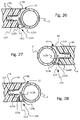
- the difference in hardness between the elastic section of the profile strip and its remaining part can be achieved by a groove which runs in the longitudinal direction in the elastic section of the profile strip.
- the groove is preferably at least essentially sealable and / or spreadable, at least when the plate element is inserted into the frame with a profile strip in between, whereby, in particular for closing and / or spreading the groove, a piping insertable in the groove or a sealing lip, in particular integrally on a groove forming the groove
- the first lip of the profile strip is provided, wherein the sealing lip is preferably connected to the first lip via a film hinge or a thin layer of material, and or a bead is preferably provided on a second lip of the profile strip forming the groove as an abutment for the sealing lip on the inside of the groove.
- the profile strip for attachment to a plate element on the latter facing side has a mounting strip or at least one mounting pin which can be inserted into a corresponding recess, such as a mounting groove or a mounting hole, in the side walls of the plate element.
- the mounting strip or the mounting pin preferably has a cross section shaped like a fir tree.
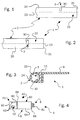
- a tube element 2 of an assembly system 1 is shown in a side view, a top view and a cross-sectional view.
- the tube element 2 has in its peripheral wall 20 an opening 3 in the form of a peripheral slot section 30 which extends transversely to the tube element axis 23.
- the circumferential slot section 30 is arranged in the end region 22 of the tubular element 20 at such a distance from the axial end 21 that an actuating end 41 of a locking device 40 (see FIG. 4) is accessible and operable through the circumferential slot section 30, as can be seen in FIGS. 6 and 7 .
- the tubular element 2 is made of metal, but could also be made of plastic or wood or a combination of materials, depending on the required durability and stability, taking into account a desired design.
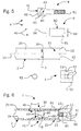
- Connecting devices 4 for connecting the tubular element 2 to an object 5, such as another tubular element 2, a wall or a node element 50 of the assembly system 1, are shown in a side view in FIG.
- the connecting devices 4 contain the locking device 40 with the actuating end 41.
- the connecting devices 4 can be pushed into the tubular element 2 with the actuating end 41 of their locking device 40 ahead, as can be seen in FIG.
- the locking device 40 contains a clamping device 6 which can be expanded radially in the circumferential direction by actuating its actuating end 41, which in the embodiment shown in FIGS. 4 to 6 is formed by the head 80 of a screw 8, by means of which the locking device 40 at least against forces in the direction against pulling the locking device 40 out of the tubular element 2 in the latter can be releasably fixed, for example by frictional engagement.
- the actuating end 41 of the locking device 40 contains four engagement recesses 42 in the form of radial bores 43 for a form-fitting approach of a tool in the screw head 80, of which, when the locking device 40 is inserted into the tubular element 2, through the opening 3 or the peripheral slot section 30 in the peripheral wall 20 of the Pipe element 2 are accessible for attaching the tool two, as is clear from FIGS. 6 and 7.
- a tool according to the design of the engagement recesses 42 in this embodiment e.g. a simple pin (not shown) can be used which fits into the radial bores 43.
- a pin such as a steel pin (not shown), which can also be provided with an ergonomically shaped handle in a known manner for better handling, has to be inserted into one of the radial bores 43 accessible through the circumferential slot section 30 be used. Then the screw head 80 can be rotated within the dimensions of the circumferential slot section 30 by means of the pin (not shown).
- the screw 8 is rotated in one direction in this way until the pin (not shown) has reached one end of the circumferential slot section 30, the pin (not shown) can be inserted into the other radial bore, which is simultaneously accessible through the circumferential slot section 30 are, so that again the entire length of the circumferential slot portion 30 is available for further rotation of the screw 8 in the same direction.
- the screw 8 can also be turned in the same way in the other direction.
- the screw 8 acting to actuate the clamping device 6 of the locking device 40 can thus be used to fix and release the locking device 40 in the tubular element 2 and to connect the connecting devices 4 can be rotated with the object 5 in the circumferential direction of the tubular element 2.
- the position of the opening 3 or of the circumferential slot section 30 determining this in the end region 22 of the tubular element 2 is selected such that it or he is at a distance from the axial end 21 of the tubular element which is matched to the actuating end 41 of the locking device 40 inserted into the tubular element 2 2 is arranged. Then, the operating end 41 of the locking device 40 can be operated through the circumferential slot portion 30 in the manner described above.
- the clamping device 6 adjustable by the screw 8 is provided in the embodiment of FIGS.
- the clamping device 6 also contains a tubular elastic element 60, which is formed by a rubber hose 61, and two washers 66 on the open ends of the rubber hose 61 (see Figure 5). The screw 8 is inserted in sequence through the first washer 66, then through the elastic hose 61 and finally through the second washer 66, as can be seen from FIG. 4.
- the elastic hose 61 allows the clamping device 6 to be frictionally engaged with the tubular element 2 if the locking device is inserted coaxially into the tubular element 2 as in FIG. This is done by turning the actuation end 41 of the locking device 40 by turning the screw 8 through the pin (not shown) inserted into a radial bore 43 of its head 80. In order to thereby achieve a radial widening of the elastic hose 61 against the inner wall 24 of the tubular element 2, the hose 61 must be compressed between the two washers 66.
- the length, elasticity, material thickness and other physical properties of the hose 61 can be within the scope of the expert Can easily be optimized to ensure at least one holding force against pulling the clamping device 6 out of the tubular element 2 in the axial direction 23 thereof in the intended application.
- the hose 61 can also be made of another material, such as plastic or spring steel, instead of rubber.
- the elasticity of the hose 61 brings besides the simple and safe producibility of the force or friction connection the advantage that the elastic element 60 when releasing the connection or locking by turning the screw 8 in the other direction with respect to the locking movement automatically and reliably in an unclamped Return position in which the locking device 40 is axially freely displaceable in the tubular element 2. This means that the connecting devices 4 can then be easily separated from the tubular element.
- the design of the hose 61 made of rubber also has the advantage that a good adhesive or frictional connection between the rubber surface of the hose 61 and the inner wall 24 of the tubular element 2 is achieved.
- this advantage can alternatively also be realized by means of elastic elements 60 with corresponding coatings on the outside or other materials and material combinations.
- the two washers 66 also bring yet another advantage in addition to their function to prevent the elastic hose 61 from rotating or twisting when the screw 8 is turned. Because the outer diameter of the two washers 66 and the screw head 80 are only slightly smaller than the inner diameter of the Is tubular element 2, the screw head 80 and the two washers 66 ensure secure axial guidance of the locking device 40 or its clamping device 6 within the tubular element 2, so that the tilting or tilting of the Clamping device 6 within the tubular element 2 is avoided.
- the tubular element 2 of the assembly system 1 is screwed onto an object 5, such as the node element 50 (by means of a rotary actuation at the actuating end 41 of the screw 8 (see Figures 5 and 6) or attached to another tubular element 2 (see Figure 7).
- the screw 8 has a length such that its free thread end 81 protrudes over the attached components of the first washer 66, elastic hose 61 and second washer 66. This threaded end can easily be screwed into a threaded opening 51 of an object 5 by turning the screw 8 in the manner described above in order to fasten the tubular element 2 to the object 5 via the connecting devices 4.
- the radial bores 43 can have a length in the axial direction corresponding to this axial movement of the screw 8, ie they can be designed as elongated holes.
- two end slots 43 '(FIG. 8) can also be introduced from the free end 82 of the screw head 80 into the screw head 80 with a corresponding axial length.
- Two engagement recesses 42 in the periphery of the actuating end 41 of the locking device 40 are sufficient in the embodiment described above if they are spaced apart in the circumferential direction such that they are both accessible simultaneously through the opening 3 or the circumferential slot section 30.
- the circumferential slot section 30 must then extend over more than 180 °.
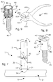
- the screw head 80 is provided with a toothing 44, as is the case with the further embodiment shown in FIG. 9, a relatively small opening 3 can be used, since the toothing 44 thus acts as a gear 45 trained screw head 80 provides a relatively small pitch that allows positive engagement of a tool 451 at small angular intervals, as is also shown, for example, in FIG.
- the tool 451 is designed as pliers, which on each arm 452, 453 contains a tooth formation 454 matching the toothing 44 and two grippers 455.
- the two tooth formations 454 adjoin each other while the pliers 451 are closed and, if the pipe element 2 is suitably gripped with the pliers 451, can engage in the toothing 44 of the screw head 80 through the opening 3 or the circumferential slot section 30.
- the two grippers 455 then grip around the tubular element 2, as it were, as a guide and anti-slip device. If one end of the opening 3 in the circumferential direction of the tubular element 2 is reached during a working rotary movement of the screw 8 with this tool 451, the pliers 451 need only be opened, offset against the working rotational movement up to the other end of the opening 3 in the circumferential direction of the tubular element 2 and then again be closed in order to have the extent of the opening 3 in the direction of the working rotary movement again fully available. To facilitate this process, the pliers 451 can be biased into their open position.
- a motor-driven tool such as a cordless screwdriver with a corresponding gear insert (not shown), can be used, which fits the gear 45 of the screw 8 and can have a cover for safety reasons, which at the same time serves as a starting aid for positioning and holding the Cordless screwdriver can serve.
- the design of the screw head 80 as a gear 45 enables the toothing 44 to be of sufficient length in the direction of the tube element axis 23 in a particularly simple manner.
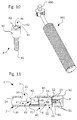
- FIG. 1 A hexagon socket configuration 46 is shown as an example in FIG.
- a conventional tool such as an Allen key 460 in the case shown, can also be used to actuate such a screw 8, as is also shown schematically in FIG.
- an axial slot section 31 is provided which forms a T-shape together with the circumferential slot section 30 or, as FIG. 11 shows, for example, in comparison with FIG. 6, an axial extension of the whole Circumferential slot portion 30 is.
- the Allen key 460 at the end of the circumferential slot section 30 from the Allen key 46 of the screw 8 contains a ratchet or ratchet device with a switchable working direction.
- the switchover option which is indicated by a double arrow and "L" for left-hand rotation and "R” for right-hand rotation in FIG. 10, is preferably outside the tubular element 2 when the tool 8 is attached to the screw 8. If no ratchet device 461 is used, the axial slot section must be used 31 in the circumferential direction of the tubular element 2 have the same extent as possible as the circumferential slot section 30 in order to be able to reliably attach the tool 460 to the screw head 80 in any of its rotational positions.
- the outer diameter of the actuating end 41 of the locking device 40 has a slightly smaller dimension than the inner diameter of the tubular element 2, preferably for guiding purposes, has already been explained above.
- the actuating end 41 of the locking device 40 has an axial length that is greater than the axial extent of the opening 3 in the peripheral wall 20 of the tubular element 2. This compensates for the weakening of the tubular element 2 through the opening 3, so that the tubular element 2 also has at least the same stability and rigidity in the region of its opening 3 as in its remaining length profile.
- an opening 3 can be provided in the peripheral wall 20 of the tubular element 2 in each of the two axial end regions 22 of the tubular element 2.
- the tubular element can be attached with its two ends in the same way to an object 5, such as a node element 50 (see FIG. 5).
- an object 5 such as a node element 50 (see FIG. 5).
- a node element 50 with only 3 threaded bores 51 is used, a pipe element 2 being connected to a first bore 51 by means of connecting devices 4, a second bore 51 being connected only to connecting devices 4, and the third bore 51 is still free.
- a node element 50 can be used, for example, on a corner of an upper floor of a shelf or on a corner of a table.
- the height of the tables can be individually adjusted using special elements.
- the modular design allows a simple combination of any combination of basic components not only for tables, but also for other furniture, including beds and special furniture.
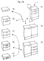
- Cabinet elements the size of a Briefcases as possibly even a mobile unit up to an entire wall unit are shown in perspective in FIGS. 18A to 18H and in front and side views in FIGS. 19A and 19B.
- Reference numerals are also only representative of some parts here, since the assignments are already readily apparent from the figures themselves.
- a sealing element or sealing elements 11 can be used to cover and preferably seal the opening or openings 3 in the peripheral wall 20 of the tubular element 2 can be provided, as shown in Figures 3 and 7.
- These sealing elements 11 can both cover the opening (s) 3 in the tubular elements 2 and also enable the transition between the tubular elements 2 with one another and to the node elements 50 and the plate elements 9.
- the material and / or the shape of the sealing lip 113, the film hinge 113a and / or the bead 113b can force or pretension the sealing lip 113 into the sealing position shown in FIG.
- a tight transition between the plate element 9 and the tubular elements 2 surrounding it and a good holding effect of the plate element 9 in the frame 10 is achieved.
- the profile strips 11 and possibly the piping 111 are preferably made of an elastic material, such as a plastic or rubber or a composite material thereof, possibly with other components, in particular reinforcing and / or stiffening components.
- the elasticity required, depending on the desired function of the profile strips 11, can be achieved can also be supported by the shape of the profile strips 11.
- the plate element 9 is loosely inserted into the frame 10, where it is preferably held by at least temporarily acting support means (not shown) or only manually, and then the profile strip 11 between the plate element 9 and the frame parts is pressed.
- the assembly system can advantageously be supplemented by some other small but effective parts.
- alignment means 12, 13 are included, by means of which a predeterminable relative position of the tubular element 2 and object 5, on which the tubular element 2 can be attached, in particular with regard to the rotational position of the tubular element 2 about its axis 23, is adjustable.
- these alignment means contain an adjusting pin 12 at the end 21 of the tubular element 2 and a receiving bore 13 in the node element 50 at a corresponding distance from the bore 51, as shown in FIGS. 5 and 6.
- a plurality of receiving bores 13 can also be provided in the node element 50 in order to enable a corresponding number of positions of the tubular element 2 relative to the node element 50, as can be seen from FIG. 6, for example.
- plate elements 9 can be used therein.
- a frame 10 for a plate element 9 may not be fully assembled before the plate element 9 is inserted, e.g. must be inserted into the subframe. Only then can the frame 10 be completed. This depends on the edge profile of the plate elements 9. The edge profile may or may not allow it to be pressed into a finished peripheral frame 10.
- the two-part cylinder of the clamping device which can also be referred to as a dowel
- the two-part cylinder of the clamping device can have any other division than the aforementioned ones, as long as it contains run-up or ramp surfaces which run obliquely to its axis and which cause the dowel to expand radially due to an axial compression.
- the clamping or locking device can also have any other design which enables bending, bulging, swiveling out or unfolding of at least part of the clamping or locking device as a result of an actuation movement in the axial direction of the tubular element.
- the hose which is one of preferred configurations of the locking device, any other similar squeeze piece can be used.
- connection devices in connection with a corresponding thread in the object can be replaced by any other suitable connection element for which there is a corresponding counter-formation in the object.
- Appropriate configurations of such a connecting element can be used, for example, to ensure that its rotation initially locks or locks it in the tubular element and that the fixed connection to the object is produced by further rotation.
- these two parts can be connected to one another in a rotationally fixed manner, for example if such a spreading of a four-part end of the connecting devices (similar to the eighth embodiment according to FIG. 15) can be achieved within a hole in the node element that the four Wing can be positively inserted into corresponding recesses in the circumference of the hole.
- knot or cube elements as connecting links between tubular elements for the individual assembly point
- exactly suitable knot or cube elements can be used.
- the node or cube elements only need to have as many mounting holes as are required at the respective point. This avoids holes that are difficult to clean, which is particularly advantageous for the use of the mounting system in healthcare, for example for furniture structures. Due to the design of the tubular elements according to the invention, if an extension is to be carried out at a point where there are no free node connection holes, the corresponding nodes can easily be replaced without further dismantling work being required.
- the circumferential slot section in the circumferential wall of the tubular element in any case does not weaken the tubular element in this area, e.g. a screw head is used as the actuating end of the connecting devices, which has a greater axial length than the circumferential slot section, and whose outer diameter is at most slightly smaller than the inner diameter of the tubular element.
- the invention also allows tubular elements to be connected to one another both axially and in a T-shape. Possibly. can be used with a T-connector to realize a positive transition between the blunt flat end of a first tubular element and the curved peripheral wall of a second tubular element to which the first tubular element is to be attached.
- a threaded nut In the second tubular element, for example, only a threaded nut needs to be seated in a rotationally fixed manner behind a corresponding hole in the peripheral wall.
- a Axial connection can be used, for example, in a rotationally fixed manner in the first tubular element. Any angle positions between two pipe elements are possible both for pipe elements directly with one another and in connection with intermediate elements such as node elements.
- tubular elements to perforated sheets, for example by means of the connecting devices, and to use the tubular elements, for example, as a lamp holder, picture holder, cutlery and crockery holder, wall shelf support, book support or for attaching other objects and equipment.
- connection holes at a 30 °, 45 °, 60 ° or 90 ° distance.
- Corresponding node elements can also be used which have a cube or spherical shape as a base or any, but preferably regular, polyhedral shape.
- a wide variety of rubber profiles can also be used between the individual components of the assembly system in order to achieve the required sealing.
- Corresponding and suitably arranged rubber or plastic sealing profiles are also suitable for closing any circumferential slot section in the circumferential wall of the tubular element.
- a poison or medication cabinet which is gas-tight, can also be assembled using the assembly system according to the invention.
- the profile strip is preferably an extruder strip.
- reinforcements or stiffeners such as Work plastic or metal strips, especially spring steel strips, into the profile strip.
- this design enables a rational endless production, whereby the required lengths of the profile strip can easily be cut from a larger length.
- the use of elastic elements as components of the connecting devices also has the advantage that a screw connection or the like. thereby being held in tension at the same time and is therefore particularly strong and stable. Since the screw connection or similar cannot accidentally loosen between the connection devices and, for example, a node element, the connection is very secure, even if the screw engagement takes place over only a few, one or only part of a thread revolution.
Landscapes
- Engineering & Computer Science (AREA)
- General Engineering & Computer Science (AREA)
- Mechanical Engineering (AREA)
- Mutual Connection Of Rods And Tubes (AREA)
Applications Claiming Priority (4)
| Application Number | Priority Date | Filing Date | Title |
|---|---|---|---|
| DE1996115013 DE19615013A1 (de) | 1996-04-16 | 1996-04-16 | Montagesystem |
| DE19615013 | 1996-04-16 | ||
| DE29617989U | 1996-10-16 | ||
| DE29617989U DE29617989U1 (de) | 1996-04-16 | 1996-10-16 | Möbelsystem und Profilleiste dafür |
Publications (1)
| Publication Number | Publication Date |
|---|---|
| EP0802335A1 true EP0802335A1 (fr) | 1997-10-22 |
Family
ID=26024793
Family Applications (1)
| Application Number | Title | Priority Date | Filing Date |
|---|---|---|---|
| EP97106312A Withdrawn EP0802335A1 (fr) | 1996-04-16 | 1997-04-16 | Système de montage, procédé pour son montage et bande profilée pour le système de montage |
Country Status (1)
| Country | Link |
|---|---|
| EP (1) | EP0802335A1 (fr) |
Cited By (4)
| Publication number | Priority date | Publication date | Assignee | Title |
|---|---|---|---|---|
| EP2441969A1 (fr) * | 2010-10-12 | 2012-04-18 | Marchhart GmbH | Liaison amovible entre un profilé creux et un autre élément |
| CN109455084A (zh) * | 2018-12-29 | 2019-03-12 | 江阴道达汽车饰件有限公司 | 一种反向装配格栅亮条一体化的格栅总成 |
| CN111857420A (zh) * | 2020-07-14 | 2020-10-30 | 北海翰博士科技有限公司 | 一种内嵌式安装的触控面板 |
| WO2025011665A1 (fr) * | 2023-07-10 | 2025-01-16 | 杭州搭客科技有限公司 | Module de liaison et meuble assemblé modulaire |
Citations (5)
| Publication number | Priority date | Publication date | Assignee | Title |
|---|---|---|---|---|
| DE1889913U (de) * | 1964-01-17 | 1964-03-26 | Hans Eimermann | Bauelement zur herstellung von tischen und stellagen aller art. |
| DE7014538U (de) * | 1971-05-27 | Gleiss W | Rohrförmiger Bauteil mit Verbmdungs element | |
| DE2255407A1 (de) * | 1972-11-11 | 1974-05-22 | Bremshey Ag | Verbindung von sich koaxial aneinander anschliessenden rohrabschnitten |
| US4997304A (en) * | 1987-05-12 | 1991-03-05 | Choy Yau K | Connector |
| CH681907A5 (fr) * | 1990-05-09 | 1993-06-15 | Schaerer Soehne Ag Usm U |
-
1997
- 1997-04-16 EP EP97106312A patent/EP0802335A1/fr not_active Withdrawn
Patent Citations (5)
| Publication number | Priority date | Publication date | Assignee | Title |
|---|---|---|---|---|
| DE7014538U (de) * | 1971-05-27 | Gleiss W | Rohrförmiger Bauteil mit Verbmdungs element | |
| DE1889913U (de) * | 1964-01-17 | 1964-03-26 | Hans Eimermann | Bauelement zur herstellung von tischen und stellagen aller art. |
| DE2255407A1 (de) * | 1972-11-11 | 1974-05-22 | Bremshey Ag | Verbindung von sich koaxial aneinander anschliessenden rohrabschnitten |
| US4997304A (en) * | 1987-05-12 | 1991-03-05 | Choy Yau K | Connector |
| CH681907A5 (fr) * | 1990-05-09 | 1993-06-15 | Schaerer Soehne Ag Usm U |
Cited By (6)
| Publication number | Priority date | Publication date | Assignee | Title |
|---|---|---|---|---|
| EP2441969A1 (fr) * | 2010-10-12 | 2012-04-18 | Marchhart GmbH | Liaison amovible entre un profilé creux et un autre élément |
| CN109455084A (zh) * | 2018-12-29 | 2019-03-12 | 江阴道达汽车饰件有限公司 | 一种反向装配格栅亮条一体化的格栅总成 |
| CN109455084B (zh) * | 2018-12-29 | 2024-04-05 | 江阴道达汽车饰件有限公司 | 一种反向装配格栅亮条一体化的格栅总成 |
| CN111857420A (zh) * | 2020-07-14 | 2020-10-30 | 北海翰博士科技有限公司 | 一种内嵌式安装的触控面板 |
| CN111857420B (zh) * | 2020-07-14 | 2022-09-23 | 北海翰博士科技有限公司 | 一种内嵌式安装的触控面板 |
| WO2025011665A1 (fr) * | 2023-07-10 | 2025-01-16 | 杭州搭客科技有限公司 | Module de liaison et meuble assemblé modulaire |
Similar Documents
| Publication | Publication Date | Title |
|---|---|---|
| DE2906281C2 (de) | Kupplungselement | |
| DE69804077T2 (de) | Befestigungsmittel für lösbare Verbindungen von Platten | |
| EP1671562A1 (fr) | Parties de meubles avec des moyens de fixation | |
| EP0868132A1 (fr) | Systeme structural pour realiser des articles en trois dimensions | |
| EP0967701A2 (fr) | Dispositif de connexion avec protubérance de fixation divisée par des fentes au niveau des supports | |
| EP0206327B1 (fr) | Dispositif de connexion d'éléments tubulaires | |
| WO2014060608A2 (fr) | Dispositif d'assemblage démontable pour le montage sans outil | |
| EP1500829A1 (fr) | Dispositif à vis pour l'assemblage de deux pièces | |
| DE3636639A1 (de) | Bauelement-system | |
| DE3911136A1 (de) | Aufbau- und verwandlungsmoebel aus rundstaeben und anderen bauteilen | |
| DE102014113714A1 (de) | Möbelscharnier | |
| DE19615013A1 (de) | Montagesystem | |
| EP4006241A1 (fr) | Dispositif de maintien pouvant être monté sur un poteau et dispositif de maintien de douchette sanitaire | |
| EP0287981B1 (fr) | Connecteur pour le raccordement de deux éléments | |
| DE20019594U1 (de) | Justiervorrichtung eines Rahmens | |
| EP1116457A1 (fr) | Système de construction pour cadres, meubles ou similaire | |
| EP0702914B1 (fr) | Elément de tiroir d'ameublement pour tiroirs ou similaires | |
| DE3712990C2 (fr) | ||
| CH693422A5 (de) | Verbindungselement für Rahmenprofile. | |
| AT528665B1 (de) | Befestigungsvorrichtung zur Befestigung eines Schubladenelements an einer Schubladenseitenzarge | |
| EP0628736A2 (fr) | Meuble avec un cadre constitué de tuyaux | |
| EP3406918B1 (fr) | Procédé permettant de raccorder de manière détachable un premier et un second composantd'étagère pour un meuble de rangement et meuble de rangement | |
| DE102006001045B4 (de) | Eckverbinder für Tür- oder Fensterrahmen | |
| EP3054810B1 (fr) | Système de noeuds d'assemblage et kit d'assemblage | |
| DE10030919A1 (de) | Zerlegbarer Profilrahmen sowie Tischsystem mit einem solchen Profilrohrrahmen |
Legal Events
| Date | Code | Title | Description |
|---|---|---|---|
| PUAI | Public reference made under article 153(3) epc to a published international application that has entered the european phase |
Free format text: ORIGINAL CODE: 0009012 |
|
| AK | Designated contracting states |
Kind code of ref document: A1 Designated state(s): AT BE CH DE DK ES FI FR GB GR IE IT LI LU MC NL PT SE |
|
| 17P | Request for examination filed |
Effective date: 19980421 |
|
| 17Q | First examination report despatched |
Effective date: 19980608 |
|
| STAA | Information on the status of an ep patent application or granted ep patent |
Free format text: STATUS: THE APPLICATION IS DEEMED TO BE WITHDRAWN |
|
| 18D | Application deemed to be withdrawn |
Effective date: 19990803 |