EP0802387B1 - Pistolet automatique muni d'un ressort anti-recul qui peut être découplé de la culasse - Google Patents
Pistolet automatique muni d'un ressort anti-recul qui peut être découplé de la culasse Download PDFInfo
- Publication number
- EP0802387B1 EP0802387B1 EP97302540A EP97302540A EP0802387B1 EP 0802387 B1 EP0802387 B1 EP 0802387B1 EP 97302540 A EP97302540 A EP 97302540A EP 97302540 A EP97302540 A EP 97302540A EP 0802387 B1 EP0802387 B1 EP 0802387B1
- Authority
- EP
- European Patent Office
- Prior art keywords
- slide
- pistol
- coupling
- coupling member
- decoupling
- Prior art date
- Legal status (The legal status is an assumption and is not a legal conclusion. Google has not performed a legal analysis and makes no representation as to the accuracy of the status listed.)
- Expired - Lifetime
Links
- 230000008878 coupling Effects 0.000 claims abstract description 67
- 238000010168 coupling process Methods 0.000 claims abstract description 67
- 238000005859 coupling reaction Methods 0.000 claims abstract description 67
- 238000010304 firing Methods 0.000 claims description 9
- CDFSOKHNACTNPU-GHUQRRHWSA-N 3-[(1r,3s,5s,8r,9s,10s,11r,13r,17r)-1,5,11,14-tetrahydroxy-10,13-dimethyl-3-[(2r,3r,4r,5s,6s)-3,4,5-trihydroxy-6-methyloxan-2-yl]oxy-2,3,4,6,7,8,9,11,12,15,16,17-dodecahydro-1h-cyclopenta[a]phenanthren-17-yl]-2h-furan-5-one Chemical compound O[C@@H]1[C@H](O)[C@H](O)[C@H](C)O[C@H]1O[C@@H]1C[C@@]2(O)CC[C@H]3C4(O)CC[C@H](C=5COC(=O)C=5)[C@@]4(C)C[C@@H](O)[C@@H]3[C@@]2(C)[C@H](O)C1 CDFSOKHNACTNPU-GHUQRRHWSA-N 0.000 claims 1
- 238000010276 construction Methods 0.000 description 8
- 230000009471 action Effects 0.000 description 4
- 230000007246 mechanism Effects 0.000 description 3
- 230000004048 modification Effects 0.000 description 3
- 238000012986 modification Methods 0.000 description 3
- 230000000295 complement effect Effects 0.000 description 1
- 230000006835 compression Effects 0.000 description 1
- 238000007906 compression Methods 0.000 description 1
- 239000000463 material Substances 0.000 description 1
- 239000002184 metal Substances 0.000 description 1
- 238000002360 preparation method Methods 0.000 description 1
Images


Classifications
-
- F—MECHANICAL ENGINEERING; LIGHTING; HEATING; WEAPONS; BLASTING
- F41—WEAPONS
- F41A—FUNCTIONAL FEATURES OR DETAILS COMMON TO BOTH SMALLARMS AND ORDNANCE, e.g. CANNONS; MOUNTINGS FOR SMALLARMS OR ORDNANCE
- F41A3/00—Breech mechanisms, e.g. locks
- F41A3/64—Mounting of breech-blocks; Accessories for breech-blocks or breech-block mountings
- F41A3/78—Bolt buffer or recuperator means
- F41A3/82—Coil spring buffers
Definitions
- the present invention relates to semi-automatic pistols, and particularly to an easy action cocking mechanism for such pistols.
- Semi-automatic pistols commonly include a slide normally in a forward position on the frame but movable rearwardly of the frame by the recoil produced by a fired cartridge, and a recoil spring coupled to the slide so as to be stressed by the rearward movement of the slide, and thereafter to relax to return the slide to its normal forward position and to load another cartridge into the chamber.
- Such pistols are loaded by inserting a magazine of cartridges into the butt of the pistol, and manually drawing the slide against the action of the recoil spring, and then releasing it, to load the first cartridge into the firing chamber and to cock the hammer. After each firing of a cartridge, the pistol thereafter utilizes the recoil produced by the firing of the cartridge to introduce a new cartridge into the chamber and to cock the pistol.
- GB-A-MO 4804/1912 discloses a semi-automatic pistol including a frame having a chamber for loading a cartridge. There is provided a barrel through which cartridges are fired, a slide normally in a forward position on the frame but movable rearwardly of the frame by the recoil produced by a fired cartridge and recall spring normally coupled to the slide so as to be stressed by the rearward movement of the slide and thereafter to relax to return the slide to its normal forward position and to load another cartridge into the chamber.
- a manually movable decoupling assembly is provided and includes a finger grip carried by the slide and manually movable with respect thereto.
- a coupling member is normally in coupling position coupling the recoil spring to the slide but is movable, on movement of the finger grip with respect to the slide, to a decoupling position in which the recoil spring is decoupled from the slide.
- a semi-automatic pistol including a frame having a chamber for loading a cartridge, a barrel through which cartridges are fired, a slide normally in a forward position on the frame but movable rearwardly of the frame by the recoil produced by a fired cartridge and a recoil spring normally coupled to the slide so as to be stressed by the rearward movement of the slide and thereafter to relax to return the slide to its normal forward position and to load another cartridge into the chamber, said pistol further including a manually movable decoupling assembly which is manually movable from a coupling position coupling the recoil spring to the slide, to a decoupling position decoupling the recoil spring from the slide and permitting the slide to be manually moved rearwardly of the frame and then to be returned to its normal forward position, by which means a cartridge is loadable into the chamber without stressing said recoil spring; said manually movable decoupling assembly includes a finger grip carried by said slide and manually movable with respect thereto, and a coupling member
- the slide may be manually decoupled from the recoil spring in order to permit the slide to be manually moved rearwardly and then to be returned forwardly with a minimum of effort when loading the first cartridge into the chamber, thereby relieving the user from the very substantial pulling force required to load the cartridge.
- the effort for manually drawing-back the slide is reduced by about 80%, e.g., from the usual 7.0 kilograms to about 1.5 kilograms, sufficient only to feed the next cartridge into the chamber and to cock the hammer.
- the pistol since the recoil spring is decoupled from the slide during the first-cartridge loading operation, the pistol may use a stronger recoil spring, if desired, to better absorb the recoil action.
- a semi-automatic pistol according to the invention permits the user to load the first cartridge into the chamber by the same hand movements as before, except that in this case the user grips the finger grip carried by the slide, rather than the slide directly, which thereby automatically decouples the slide from the recoil spring as the finger grip traverses the lost-motion connection with respect to the slide. Further manual movement of the finger grip rearwardly, and then manual movement of the finger grip forwardly, also move the slide with it while the slide is decoupled from the recoil spring.
- the semi-automatic pistol illustrated in Fig. 1 is a known type pistol. It includes a frame 2 having a butt 3 for receiving a magazine 4 carrying cartridges (not shown) to be loaded into the chamber (not shown) at the rear end of its barrel 5 through which the cartridges are fired by actuating a hammer 6.
- Frame 2 further includes a slide 7 formed with a bore 8 (Fig. 2) for receiving barrel 5, and further formed with a bore 9 for receiving a recoil spring assembly 10.
- Assembly 10 includes a coiled spring 11 received on a central rod 12.
- the front end of the spring 11 includes a collar 13 slidable along the rod 11 when the spring 12 is compressed.
- the rear end of rod 12 is formed with an enlarged head 14 engageable with a fixed element of the frame 2 to prevent movement of the rod 12 during the compression of the spring 11.
- the front end of bore 9 is formed with an annular shoulder (not shown) engageable with collar 13, such that coiled spring 11 normally urges the slide 7 to a forward position on the frame 2, but is movable rearwardly of the frame 2 by the recoil produced when a cartridge is fired, or when manually cocked.
- Spring 11, being thus normally coupled to the slide 7, is stressed (i.e., compressed) by the rearward movement of the slide 7 as a result of the recoil produced by the fired cartridge, and thereafter relaxes (i.e., expands) to return the slide 7 to its normal forward position, while loading another cartridge into the chamber and cocking the hammer 6 in preparation for firing the next cartridge.
- the present invention provides a manually movable decoupling assembly which is manually movable from its normal coupling position, coupling the recoil spring 11 to the slide 7, to a decoupling position decoupling the spring 11 from the slide 7, thereby permitting the slide 7 to be manually moved only with a relatively small effort rearwardly of the frame 2 and then forwardly to its normal position for loading the first cartridge into the chamber.
- a manually movable decoupling assembly which is manually movable from its normal coupling position, coupling the recoil spring 11 to the slide 7, to a decoupling position decoupling the spring 11 from the slide 7, thereby permitting the slide 7 to be manually moved only with a relatively small effort rearwardly of the frame 2 and then forwardly to its normal position for loading the first cartridge into the chamber.
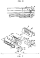
- Fig. 2 The main components of the manually movable decoupling assembly are illustrated in Fig. 2. They include a finger grip 20 carried on slide 7, an actuator member 21 secured to finger grip 20 by a pin 22 passing through aligned holes 22a, 22b therein, and a coupling member 23 receivable within an inclined slot 24 in slide 7 and movable by actuator member 21 either to a lower coupling position with respect to recoil spring 11 (Fig. 3) or to an upper decoupled position (Fig, 4a, 4b) with respect to spring 11.
- Finger grip 20 is preferably made of a plastic material. It is formed with a central strip 20a to overlie the upper surface of slide 7, and a pair of diverging side strips 20b, 20c to straddle the opposite sides of the slide 7.
- Actuator member 21 which is secured to finger grip 20 by pin 22, is similarly formed with a central strip 21a to overlie the upper edge of slide 7, and with a pair of diverging side strips 21b, 21c to straddle the opposite sides of the slide 7.
- Side strips 21b, 21c are formed with cutouts 25, 26 open at their tops, and with inclined closed slots 27, 28 forwardly of the outputs.
- the forward end of the center strip 21a is formed with a depending lug 29 overlying the cutouts 25, 26, and the rear end of the center strip is formed with an edge slot 30.
- Coupling member 23 is in the form of a metal plate of a thickness to be received within the inclined slot 24 in slide 7.
- a pair of projecting pins or rollers 31, 32 are carried at the opposite sides at the upper end of coupling member 23 and are receivable within the inclined slots 27, 28 formed in the side strips 21b, 21c of the actuator member 21.
- the lower end of coupling member 23 is formed with a semicircular recess 33 conforming to the curvature of the center rod 11 in the recoil spring assembly 10; and the upper end of coupling member 23 is formed with a semi- circular recess 34 conforming to the curvature of the barrel 5 within bore 8 ofthe slide 7.
- slide 7 The upper surface of slide 7 is formed with an elongated recess 36 receiving a biasing spring 37, and with an opening 38 at its rear end.
- Recess 36 in slide 7 receives depending lug 29 of the actuator member 21, and biasing spring 37 biases the actuator member 21 forwardly of the slide 7.
- lug 29 of the actuator member movable within recess 36 of the slide 7, provides a lost-motion connection between the actuator member 21 and the slide, permitting the actuator member 21 to move a short distance rearwardly of the slide 7 before further rearward movement of the actuator member 21 also moves the slide 7 with it.
- Slide 7 is formed with a pair of recesses 7a, 7b, separated by a shallower recess 7c, on each of its opposite sides for accommodating the side strips 21b, 21c of actuator member 21. These recesses also guide the movement of the actuator member 21, together with the finger grip 20, provided by the above lost-motion connection.
- the barrel 5 is provided a plurality of teeth 5a (Fig. 3) receivable with complementary recesses 7d formed in the slide 7 when the slide 7 is in its normal forward position and the barrel 5 is locked to the slide 7.
- the conventional pistol also includes mechanism (not shown herein) which assures that the foregoing conditions are present before the pistol can be fired.
- This mechanism may also be used in the novel construction of the present invention, particularly as illustrated in Figs. 2 and 3, to prevent the pistol from being fired unless finger grip 20 and its actuator member 21 are in their normal forward positions with respect to slide 7.
- slide 7 further includes a locking member 40 formed at its front end with an upstanding lug 41.
- lug 41 normally passes through opening 38 in the slide when the slide is in its normal forward position, such that member 40 does not interfere with barrel teeth 5a being received within recesses 7d of the slide 7 which, as described above, locks the barrel 5 to the slide and enables the pistol to be fired.
- the center strip 21a of actuator member 21 thus prevents lug 41 from assuming the above position, and thereby prevents firing of the pistol, at all times except when lug 41 is not only aligned with opening 38, but also with slot 30, in actuator member 21.
- the forward end of bore 9 receiving the recoil spring assembly 10 is formed with an annular shoulder engageable with collar 13 of the spring assembly to couple the slide 7 to the spring assembly 10.
- no such shoulder is formed in bore 9, but rather coupling member 23, when in its normal position as illustrated in Fig. 3, couples the slide 7 to the recoil spring assembly 10.
- a retainer member 43 preferably as shown in Fig. 2, is therefore provided normally engageable with the enlarged rear end 14 of the central rod 12 of the recoil spring assembly 10 for retaining the spring assembly against the frame 2 and within bore 9 of slide 7.
- retainer member 43 is pivotally mounted at 44 to the frame 2 and is biased by a spring 45 to bring its upper end 46 into engagement with the enlarged end 14 of the spring assembly rod 12 to normally hold the spring assembly 10 to frame 2 and within bore 9 of the slide 7.
- retainer member 43 is pressed at its surface 47, on the side of its pivot 44 opposite to spring 45, the upper surface 46 of the retainer member 43 is lowered out of engagement with enlarged head 14 of rod 12, permitting the recoil spring assembly 10 to be removed from the frame 2, e.g., when disassembling the pistol.
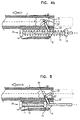
- Fig. 3 illustrates the above-described parts of the pistol in their normal positions, wherein it will be seen that the finger grip 20 and its actuator member 21 are forwardly of the slide 7, and the coupling member 23 is in its lowermost position engageable with collar 13 of the recoil spring assembly 10.
- finger grip 20 is manually gripped between the user's fingers and moved rearwardly with respect to slide 7. This is permitted by the lost-motion connection between lug 29 of actuator member 21 moving within recess 36 of slide 7, and within the side recesses 7a, 7b of the slide. This movement of actuator member 21 with respect to slide 7 occurs for a distance, e.g., about 8 mm.
- coupling member 23 is raised relative to slide 7 by virtue of its projections 31, 32 received within the closed inclined slots 27, 28 of the actuator member. Coupling member 23 is thus raised within inclined slot 24 of the slide 7 to clear collar 13 of the recoil spring assembly 10 (Fig.
- slide 7 After slide 7 has thus been manually moved to its rearward position while decoupled from the recoil spring assembly 10, it is then manually moved to its normal forward position. This introduces the first cartridge of the magazine into the pistol chamber and also cocks the hammer 6 in the conventional manner, As described earlier, lug 41 of locking member 40 not only assures that the slide 7 must be in its forward position with respect to the pistol frame 2, but also that actuator member 21 and its finger grip 20 must be in their forward positions with respect to the slide 7, before the pistol can fire.
- the pistol After the pistol has thus been loaded with the first cartridge and cocked ready for firing, it therefore operates in the conventional manner to reload the chamber with a new cartridge after each firing since coupling member 23 is in its normal lower position, as shown in Fig. 5, thereby coupling the recoil spring assembly 10 to the slide 7.
- Fig. 6 illustrates a modification in the construction, wherein the actuator member 21, instead of being provided with closed inclined slots 27, 28 for moving the coupling member 23 from its lower coupling position to its upper decoupling position, is formed with open cam surfaces 50.
- the actuator member 21, instead of being provided with closed inclined slots 27, 28 for moving the coupling member 23 from its lower coupling position to its upper decoupling position is formed with open cam surfaces 50.
- piano springs 52 are provided engageable with the coupling member side projections 31, 32 to urge them downwardly into engagement with these open cam surfaces 50.
- Fig. 7 illustrates the invention applied to a semi-automatic pistol of the type wherein the slide 107 is provided with but a single bore 108 for the barrel, and the recoil spring assembly 110 is received within the same bore 108 and encloses the barrel 105.
- the finger grip 120 and the actuator member 121 are of the same construction as described above.
- the coupling member 123 is of a modified construction, being provided with a cavity 133 only at its lower end to accommodate the recoil spring assembly 110 and the barrel 105 within it.
- Coupling member 123 is similarly formed with two projections 131, 132 on its opposite sides, received within the closed cam slot 127, 128 formed in the actuator member, so as to raise and lower the coupling member 123 within slot 124 of the slide.
Landscapes
- Engineering & Computer Science (AREA)
- General Engineering & Computer Science (AREA)
- Toys (AREA)
- Coating Apparatus (AREA)
- Portable Nailing Machines And Staplers (AREA)
- Food-Manufacturing Devices (AREA)
- Display Devices Of Pinball Game Machines (AREA)
Claims (14)
- Pistolet semi-automatique comprenant un cadre (2) possédant une chambre permettant de charger une cartouche, un canon (5) à travers lequel sont tirées des cartouches, une glissière (7) généralement en position avant sur le cadre (2) mais se déplaçant vers l'arrière du fait du recul produit par une cartouche tirée et un ressort anti-recul (11) généralement accouplé à la glissière (7) de telle sorte qu'il est comprimé par le mouvement arrière de la glissière (7) et qu'il se relâche ensuite pour remettre la glissière (7) dans sa position avant normale et pour permettre le chargement d'une autre cartouche dans la chambre,
ledit pistolet comprenant en outre un ensemble de découplage à déplacement manuel qui peut être déplacé manuellement d'une position de couplage accouplant le ressort anti-recul à la glissière (7), à une position de découplage désaccouplant le ressort anti-recul (11) de la glissière et permettant à la glissière (7) d'être déplacée manuellement vers l'arrière du cadre (2) et de retourner ensuite dans sa position avant normale, moyennant quoi une cartouche peut être chargée dans la chambre sans comprimer ledit ressort anti-recul (11) ; ledit ensemble de découplage à déplacement manuel comprend une prise pour les doigts (20) supportée par ladite glissière (7) et pouvant être déplacée manuellement par rapport à celle-ci, et un élément de couplage (23) généralement en position de couplage permettant l'accouplement du ressort anti-recul (11) à la glissière (7), mais pouvant se déplacer, sur mouvement de ladite prise pour les doigts (20) par rapport à ladite glissière (7), dans une position de découplage désaccouplant le ressort anti-recul (11) de la glissière (7) ;
dans lequel ladite prise pour les doigts (20) présente une liaison à mouvement perdu avec la glissière (7), est normalement inclinée vers l'avant de la glissière par un ressort d'inclinaison (37) mais peut être déplacée vers l'arrière du cadre (2) de telle sorte que le mouvement manuel initial de la prise pour les doigts (20) vers l'arrière du cadre (2) n'entraíne pas le déplacement de la glissière (7) mais entraíne le déplacement de l'élément de couplage (23) de sa position de couplage à sa position de découplage, et un mouvement manuel supplémentaire de la prise pour les doigts (20) vers l'arrière du cadre (2) entraíne également avec elle le déplacement de la glissière (7) alors que la glissière (7) est découplée du ressort anti-recul (11). - Pistolet selon la revendication 1, dans lequel l'ensemble de découplage à déplacement manuel comprend en outre un élément actionneur (21) fixé à ladite prise pour les doigts (20) de telle sorte qu'il se déplace en outre à partir d'une position avant normale vers une position arrière par rapport à la glissière (7) ; ledit élément actionneur (21) comprenant des moyens à cames coopérant avec ledit élément de couplage (23) de telle sorte que lorsque l'élément actionneur (21) est déplacé de ladite position avant normale vers ladite position arrière, il déplace l'élément de couplage (23) de sa position de couplage à sa position de découplage.
- Pistolet selon la revendication 2, dans lequel ledit élément actionneur (21) est en forme de U et comprend une bande centrale (21a) surmontant la glissière, et une paire de bandes latérales (21b, 21c) chevauchant les côtés opposés de la glissière (7) et chevauchant également l'élément de couplage (23).
- Pistolet selon la revendication 3, dans lequel lesdits moyens à cames comprennent des surfaces à cames formées dans lesdites bandes latérales(21b, 21c) de l'élément actionneur (21) inclinées par rapport au sens de déplacement des projections d'engagement de la glissière sur les côtés respectivement opposés de l'élément de couplage (23) de telle sorte que les surfaces à came abaissent l'élément actionneur (23) en position de couplage à l'avant de la prise pour les doigts (20) et de l'élément actionneur (21) par rapport à la glissière (7), et soulèvent l'élément de couplage (23) en position de découplage à l'arrière de la prise pour les doigts (20) et de l'élément actionneur (21) par rapport à la glissière (7).
- Pistolet selon la revendication 4, dans lequel les surfaces à cames sont des encoches fermées (27, 28) formées dans les bandes latérales (21b, 21c) du membre actionneur (21).
- Pistolet selon la revendication 4, dans lequel les surfaces à cames sont formées dans les bandes latérales (21b, 21c) de l'élément actionneur (21) et ladite prise pour les doigts (20) comprend en outre des ressorts d'engagement engageant les projections d'engagement de la glissière sur les côtés respectivement opposés de l'élément de couplage par rapport auxdites surfaces à came.
- Pistolet selon la revendication 3, dans lequel les côtés opposés de ladite glissière forment un creux pour permettre de loger lesdites bandes latérales de l'élément actionneur.
- Pistolet selon la revendication 3, dans lequel ladite bande centrale (21a) de l'élément actionneur (21) comprend une patte (29) dans laquelle s'engage ledit ressort d'inclinaison (37) afin d'incliner ledit élément actionneur (21) et la prise pour les doigts (20) fixée à celui-ci, dans sa position avant normale sur la glissière.
- Pistolet selon la revendication 3, dans lequel ladite bande centrale de l'élément actionneur comprend en outre une encoche agencée pour recevoir une patte située sur la glissière lorsque l'élément actionneur est dans sa position avant normale par rapport à la glissière, laquelle patte permet le déplacement de la glissière par rapport à sa position avant normale et le tir du pistolet uniquement lorsqu'elle est reçue dans ladite encoche.
- Pistolet selon la revendication 1, dans lequel ledit élément de couplage est de la forme d'une plaque se déplaçant à l'intérieur d'une encoche formée dans la glissière vers lesdites positions de couplage et de découplage de l'élément de couplage.
- Pistolet selon la revendication 10, dans lequel le ressort anti-recul est un ressort anti-recul (11) possédant un collier (13) au niveau de l'extrémité avant du ressort (11), ledit élément de couplage (23) pouvant être accouplé audit collier (13) dans la position de couplage de l'élément de couplage, et pouvant être découplé dudit collier (13) dans la position de découplage de l'élément de couplage.
- Pistolet selon la revendication 11, dans lequel ledit ressort anti-recul est situé sur une tige centrale, le bord inférieur dudit élément de couplage formant un creux afin de loger ladite tige centrale dans la position de couplage inférieure dudit élément de couplage, l'extrémité supérieure dudit élément de couplage formant un creux afin de loger le canon du pistolet dans la position de découplage supérieure de l'élément de couplage.
- Pistolet selon l'une quelconque des revendications 11 ou 12, dans lequel l'extrémité arrière de ladite tige comprend une tête élargie, ledit pistolet comprenant un élément de retenue dans lequel s'engage généralement ladite tête élargie, mais pouvant être déplacé manuellement pour dégager ladite tête élargie pour permettre la dépose du ressort anti-recul du pistolet.
- Pistolet selon la revendication 11, dans lequel ledit ressort enroulé renferme le canon dudit pistolet, l'extrémité inférieure de l'élément de couplage étant formée d'une cavité allongée permettant de loger ledit canon.
Applications Claiming Priority (2)
| Application Number | Priority Date | Filing Date | Title |
|---|---|---|---|
| IL11791696 | 1996-04-15 | ||
| IL11791696A IL117916A (en) | 1996-04-15 | 1996-04-15 | Semi-automatic pistol having easy cocking action |
Publications (3)
| Publication Number | Publication Date |
|---|---|
| EP0802387A2 EP0802387A2 (fr) | 1997-10-22 |
| EP0802387A3 EP0802387A3 (fr) | 1998-09-23 |
| EP0802387B1 true EP0802387B1 (fr) | 2002-01-16 |
Family
ID=11068767
Family Applications (1)
| Application Number | Title | Priority Date | Filing Date |
|---|---|---|---|
| EP97302540A Expired - Lifetime EP0802387B1 (fr) | 1996-04-15 | 1997-04-14 | Pistolet automatique muni d'un ressort anti-recul qui peut être découplé de la culasse |
Country Status (6)
| Country | Link |
|---|---|
| US (1) | US5955696A (fr) |
| EP (1) | EP0802387B1 (fr) |
| AT (1) | ATE212119T1 (fr) |
| DE (1) | DE69709565T2 (fr) |
| ES (1) | ES2171834T3 (fr) |
| IL (1) | IL117916A (fr) |
Cited By (2)
| Publication number | Priority date | Publication date | Assignee | Title |
|---|---|---|---|---|
| USD685873S1 (en) | 2012-01-05 | 2013-07-09 | Ra Brands, L.L.C. | Recoil reducer |
| US10281233B2 (en) | 2011-09-30 | 2019-05-07 | Ra Brands, L.L.C. | Recoil reducer |
Families Citing this family (9)
| Publication number | Priority date | Publication date | Assignee | Title |
|---|---|---|---|---|
| US8015741B2 (en) * | 2009-07-20 | 2011-09-13 | Douglas Hooks | Chambering and trigger safety device for handgun |
| US8931394B2 (en) * | 2010-02-23 | 2015-01-13 | Martin Bryant | Systems and methods for providing firearms with lighter cocking action |
| CO6700135A1 (es) * | 2011-12-30 | 2013-06-28 | Ind Militar Indumil | Arma de fuego corta semiautomatica cal. 9 mm de doble accion |
| US9057574B2 (en) | 2012-06-14 | 2015-06-16 | Ra Brands, L.L.C. | Thumb safety for model 1911 handgun |
| US9970727B2 (en) | 2016-01-15 | 2018-05-15 | Agency Arms, Llc | Systems and methods for barrel attachment assemblies for firearms |
| US10184738B1 (en) | 2018-05-10 | 2019-01-22 | Kel-Tec Cnc Industries, Inc. | Handgun with improved slide |
| USD828892S1 (en) | 2018-05-10 | 2018-09-18 | Kel-Tec Cnc Industries, Inc. | Handgun with improved slide |
| RU2721644C1 (ru) * | 2019-03-11 | 2020-05-21 | Рустам Гашимович Мирзоев | Система автоматического оружия с отводом части пороховых газов из канала ствола через отверстие в нем |
| IL285340B (en) | 2021-08-03 | 2022-04-01 | Israel Weapon Ind I W I Ltd | Two-piece pistol grip |
Family Cites Families (5)
| Publication number | Priority date | Publication date | Assignee | Title |
|---|---|---|---|---|
| DE300693C (fr) * | ||||
| US984519A (en) * | 1910-02-17 | 1911-02-14 | John M Browning | Firearm. |
| DE263718C (fr) * | 1912-02-26 | |||
| US4887510A (en) * | 1988-12-15 | 1989-12-19 | Wynn Richard R | Recoil locking system for a firearm |
| US4972760A (en) * | 1989-09-18 | 1990-11-27 | Mcdonnell James F | Adjustable automatic firearm recoil system |
-
1996
- 1996-04-15 IL IL11791696A patent/IL117916A/xx not_active IP Right Cessation
-
1997
- 1997-04-14 AT AT97302540T patent/ATE212119T1/de not_active IP Right Cessation
- 1997-04-14 DE DE69709565T patent/DE69709565T2/de not_active Expired - Fee Related
- 1997-04-14 ES ES97302540T patent/ES2171834T3/es not_active Expired - Lifetime
- 1997-04-14 EP EP97302540A patent/EP0802387B1/fr not_active Expired - Lifetime
- 1997-04-15 US US08/837,972 patent/US5955696A/en not_active Expired - Fee Related
Cited By (2)
| Publication number | Priority date | Publication date | Assignee | Title |
|---|---|---|---|---|
| US10281233B2 (en) | 2011-09-30 | 2019-05-07 | Ra Brands, L.L.C. | Recoil reducer |
| USD685873S1 (en) | 2012-01-05 | 2013-07-09 | Ra Brands, L.L.C. | Recoil reducer |
Also Published As
| Publication number | Publication date |
|---|---|
| DE69709565D1 (de) | 2002-02-21 |
| EP0802387A3 (fr) | 1998-09-23 |
| ATE212119T1 (de) | 2002-02-15 |
| US5955696A (en) | 1999-09-21 |
| IL117916A (en) | 2000-08-13 |
| IL117916A0 (en) | 1996-10-31 |
| EP0802387A2 (fr) | 1997-10-22 |
| DE69709565T2 (de) | 2002-10-10 |
| ES2171834T3 (es) | 2002-09-16 |
Similar Documents
| Publication | Publication Date | Title |
|---|---|---|
| US6415702B1 (en) | Double action semi-automatic handgun | |
| US4603676A (en) | Bow drawback mechanism | |
| EP0802387B1 (fr) | Pistolet automatique muni d'un ressort anti-recul qui peut être découplé de la culasse | |
| US6263607B1 (en) | Pistol having a safety for locking a disassembly lever | |
| US6865979B1 (en) | Apparatus and method for removing the slide of a semi-automatic pistol | |
| US7299581B2 (en) | Firing trigger operated bolt catch | |
| US3020662A (en) | Repeating magazine rifle with rotatable and forwardly movable barrel | |
| US4236337A (en) | Reversible sliding magazine latch for pistols | |
| US4048901A (en) | Recoil-operated automatic pistol | |
| US6243978B1 (en) | Device for controlling the feeder system of pump-action shotguns | |
| US6266909B1 (en) | Pistol having a safety for preventing firing during disassembly | |
| US5821445A (en) | Loading lever assembly for hand-operated firearms | |
| US9625231B1 (en) | Rack and pinion lever-action rifle | |
| US4999939A (en) | Breech load pistol and conversion | |
| US4914845A (en) | Breech load pistol and conversion | |
| US3785243A (en) | Rifle | |
| GB1560848A (en) | Self-loading pistol | |
| JPH0117080B2 (fr) | ||
| US4536981A (en) | Firearm assembly | |
| US4821621A (en) | Multipurpose repeating firearm having alternate firing mechanisms | |
| US5179233A (en) | Pistol | |
| US11761720B2 (en) | Carbine having a charging handle | |
| US4936035A (en) | Breech load pistol and conversion | |
| US3710493A (en) | Block action for sporting guns dropping breech | |
| US2977598A (en) | Stud driving tool |
Legal Events
| Date | Code | Title | Description |
|---|---|---|---|
| PUAI | Public reference made under article 153(3) epc to a published international application that has entered the european phase |
Free format text: ORIGINAL CODE: 0009012 |
|
| AK | Designated contracting states |
Kind code of ref document: A2 Designated state(s): AT BE CH DE DK ES FI FR GB GR IE IT LI LU NL PT SE |
|
| PUAL | Search report despatched |
Free format text: ORIGINAL CODE: 0009013 |
|
| AK | Designated contracting states |
Kind code of ref document: A3 Designated state(s): AT BE CH DE DK ES FI FR GB GR IE IT LI LU NL PT SE |
|
| 17P | Request for examination filed |
Effective date: 19990219 |
|
| 17Q | First examination report despatched |
Effective date: 20000418 |
|
| GRAG | Despatch of communication of intention to grant |
Free format text: ORIGINAL CODE: EPIDOS AGRA |
|
| RAP1 | Party data changed (applicant data changed or rights of an application transferred) |
Owner name: FABBRICA D'ARMI PIETRO BERETTA S.P.A. |
|
| RIN1 | Information on inventor provided before grant (corrected) |
Inventor name: FABBRICA D'ARMI PIETRO BERETTA S.P.A. |
|
| GRAG | Despatch of communication of intention to grant |
Free format text: ORIGINAL CODE: EPIDOS AGRA |
|
| GRAH | Despatch of communication of intention to grant a patent |
Free format text: ORIGINAL CODE: EPIDOS IGRA |
|
| GRAH | Despatch of communication of intention to grant a patent |
Free format text: ORIGINAL CODE: EPIDOS IGRA |
|
| GRAA | (expected) grant |
Free format text: ORIGINAL CODE: 0009210 |
|
| REG | Reference to a national code |
Ref country code: GB Ref legal event code: IF02 |
|
| AK | Designated contracting states |
Kind code of ref document: B1 Designated state(s): AT BE CH DE DK ES FI FR GB GR IE IT LI LU NL PT SE |
|
| PG25 | Lapsed in a contracting state [announced via postgrant information from national office to epo] |
Ref country code: NL Free format text: LAPSE BECAUSE OF FAILURE TO SUBMIT A TRANSLATION OF THE DESCRIPTION OR TO PAY THE FEE WITHIN THE PRESCRIBED TIME-LIMIT Effective date: 20020116 Ref country code: GR Free format text: LAPSE BECAUSE OF FAILURE TO SUBMIT A TRANSLATION OF THE DESCRIPTION OR TO PAY THE FEE WITHIN THE PRESCRIBED TIME-LIMIT Effective date: 20020116 Ref country code: FI Free format text: LAPSE BECAUSE OF FAILURE TO SUBMIT A TRANSLATION OF THE DESCRIPTION OR TO PAY THE FEE WITHIN THE PRESCRIBED TIME-LIMIT Effective date: 20020116 |
|
| REF | Corresponds to: |
Ref document number: 212119 Country of ref document: AT Date of ref document: 20020215 Kind code of ref document: T |
|
| REG | Reference to a national code |
Ref country code: CH Ref legal event code: EP |
|
| REG | Reference to a national code |
Ref country code: IE Ref legal event code: FG4D |
|
| REF | Corresponds to: |
Ref document number: 69709565 Country of ref document: DE Date of ref document: 20020221 |
|
| PG25 | Lapsed in a contracting state [announced via postgrant information from national office to epo] |
Ref country code: LU Free format text: LAPSE BECAUSE OF NON-PAYMENT OF DUE FEES Effective date: 20020414 |
|
| PG25 | Lapsed in a contracting state [announced via postgrant information from national office to epo] |
Ref country code: IE Free format text: LAPSE BECAUSE OF NON-PAYMENT OF DUE FEES Effective date: 20020415 |
|
| PG25 | Lapsed in a contracting state [announced via postgrant information from national office to epo] |
Ref country code: SE Free format text: LAPSE BECAUSE OF FAILURE TO SUBMIT A TRANSLATION OF THE DESCRIPTION OR TO PAY THE FEE WITHIN THE PRESCRIBED TIME-LIMIT Effective date: 20020416 Ref country code: PT Free format text: LAPSE BECAUSE OF FAILURE TO SUBMIT A TRANSLATION OF THE DESCRIPTION OR TO PAY THE FEE WITHIN THE PRESCRIBED TIME-LIMIT Effective date: 20020416 Ref country code: GB Free format text: LAPSE BECAUSE OF NON-PAYMENT OF DUE FEES Effective date: 20020416 Ref country code: DK Free format text: LAPSE BECAUSE OF FAILURE TO SUBMIT A TRANSLATION OF THE DESCRIPTION OR TO PAY THE FEE WITHIN THE PRESCRIBED TIME-LIMIT Effective date: 20020416 |
|
| REG | Reference to a national code |
Ref country code: CH Ref legal event code: NV Representative=s name: AMMANN PATENTANWAELTE AG BERN |
|
| NLV1 | Nl: lapsed or annulled due to failure to fulfill the requirements of art. 29p and 29m of the patents act | ||
| ET | Fr: translation filed | ||
| REG | Reference to a national code |
Ref country code: ES Ref legal event code: FG2A Ref document number: 2171834 Country of ref document: ES Kind code of ref document: T3 |
|
| PLBE | No opposition filed within time limit |
Free format text: ORIGINAL CODE: 0009261 |
|
| STAA | Information on the status of an ep patent application or granted ep patent |
Free format text: STATUS: NO OPPOSITION FILED WITHIN TIME LIMIT |
|
| GBPC | Gb: european patent ceased through non-payment of renewal fee |
Effective date: 20020416 |
|
| 26N | No opposition filed | ||
| REG | Reference to a national code |
Ref country code: IE Ref legal event code: MM4A |
|
| PGFP | Annual fee paid to national office [announced via postgrant information from national office to epo] |
Ref country code: FR Payment date: 20030408 Year of fee payment: 7 |
|
| PGFP | Annual fee paid to national office [announced via postgrant information from national office to epo] |
Ref country code: CH Payment date: 20030416 Year of fee payment: 7 |
|
| PGFP | Annual fee paid to national office [announced via postgrant information from national office to epo] |
Ref country code: ES Payment date: 20030429 Year of fee payment: 7 |
|
| PGFP | Annual fee paid to national office [announced via postgrant information from national office to epo] |
Ref country code: BE Payment date: 20030625 Year of fee payment: 7 |
|
| PG25 | Lapsed in a contracting state [announced via postgrant information from national office to epo] |
Ref country code: ES Free format text: LAPSE BECAUSE OF NON-PAYMENT OF DUE FEES Effective date: 20040415 |
|
| PG25 | Lapsed in a contracting state [announced via postgrant information from national office to epo] |
Ref country code: LI Free format text: LAPSE BECAUSE OF NON-PAYMENT OF DUE FEES Effective date: 20040430 Ref country code: CH Free format text: LAPSE BECAUSE OF NON-PAYMENT OF DUE FEES Effective date: 20040430 Ref country code: BE Free format text: LAPSE BECAUSE OF NON-PAYMENT OF DUE FEES Effective date: 20040430 |
|
| BERE | Be: lapsed |
Owner name: FABBRICA D'ARMI PIETRO *BERETTA S.P.A. Effective date: 20040430 |
|
| REG | Reference to a national code |
Ref country code: CH Ref legal event code: PL |
|
| PG25 | Lapsed in a contracting state [announced via postgrant information from national office to epo] |
Ref country code: FR Free format text: LAPSE BECAUSE OF NON-PAYMENT OF DUE FEES Effective date: 20041231 |
|
| REG | Reference to a national code |
Ref country code: FR Ref legal event code: ST |
|
| REG | Reference to a national code |
Ref country code: ES Ref legal event code: FD2A Effective date: 20040415 |
|
| PGFP | Annual fee paid to national office [announced via postgrant information from national office to epo] |
Ref country code: DE Payment date: 20080417 Year of fee payment: 12 |
|
| PGFP | Annual fee paid to national office [announced via postgrant information from national office to epo] |
Ref country code: AT Payment date: 20080410 Year of fee payment: 12 |
|
| PGFP | Annual fee paid to national office [announced via postgrant information from national office to epo] |
Ref country code: IT Payment date: 20080422 Year of fee payment: 12 |
|
| PG25 | Lapsed in a contracting state [announced via postgrant information from national office to epo] |
Ref country code: DE Free format text: LAPSE BECAUSE OF NON-PAYMENT OF DUE FEES Effective date: 20091103 Ref country code: AT Free format text: LAPSE BECAUSE OF NON-PAYMENT OF DUE FEES Effective date: 20090414 |
|
| PG25 | Lapsed in a contracting state [announced via postgrant information from national office to epo] |
Ref country code: IT Free format text: LAPSE BECAUSE OF NON-PAYMENT OF DUE FEES Effective date: 20090414 |