EP0802532A2 - Mécanisme de chargement de cassette à bande - Google Patents
Mécanisme de chargement de cassette à bande Download PDFInfo
- Publication number
- EP0802532A2 EP0802532A2 EP97200667A EP97200667A EP0802532A2 EP 0802532 A2 EP0802532 A2 EP 0802532A2 EP 97200667 A EP97200667 A EP 97200667A EP 97200667 A EP97200667 A EP 97200667A EP 0802532 A2 EP0802532 A2 EP 0802532A2
- Authority
- EP
- European Patent Office
- Prior art keywords
- cassette
- lift
- slot
- loading direction
- loading mechanism
- Prior art date
- Legal status (The legal status is an assumption and is not a legal conclusion. Google has not performed a legal analysis and makes no representation as to the accuracy of the status listed.)
- Granted
Links
- 230000007704 transition Effects 0.000 claims abstract description 13
- 230000008878 coupling Effects 0.000 claims abstract description 10
- 238000010168 coupling process Methods 0.000 claims abstract description 10
- 238000005859 coupling reaction Methods 0.000 claims abstract description 10
- 238000012546 transfer Methods 0.000 claims abstract description 7
- 239000000969 carrier Substances 0.000 claims description 3
- 238000004804 winding Methods 0.000 description 11
- 230000000903 blocking effect Effects 0.000 description 7
- 238000013461 design Methods 0.000 description 4
- 230000000694 effects Effects 0.000 description 4
- 230000005484 gravity Effects 0.000 description 3
- 241000549194 Euonymus europaeus Species 0.000 description 2
- 238000013459 approach Methods 0.000 description 2
- 238000009434 installation Methods 0.000 description 2
- 230000005540 biological transmission Effects 0.000 description 1
- 238000006073 displacement reaction Methods 0.000 description 1
- 238000000034 method Methods 0.000 description 1
- 238000013519 translation Methods 0.000 description 1
Images


Classifications
-
- G—PHYSICS
- G11—INFORMATION STORAGE
- G11B—INFORMATION STORAGE BASED ON RELATIVE MOVEMENT BETWEEN RECORD CARRIER AND TRANSDUCER
- G11B15/00—Driving, starting or stopping record carriers of filamentary or web form; Driving both such record carriers and heads; Guiding such record carriers or containers therefor; Control thereof; Control of operating function
- G11B15/675—Guiding containers, e.g. loading, ejecting cassettes
- G11B15/67544—Guiding containers, e.g. loading, ejecting cassettes with movement of the cassette parallel to its main side and subsequent movement perpendicular thereto, i.e. front loading
- G11B15/67547—Guiding containers, e.g. loading, ejecting cassettes with movement of the cassette parallel to its main side and subsequent movement perpendicular thereto, i.e. front loading the two movements being made by the cassette holder
-
- G—PHYSICS
- G11—INFORMATION STORAGE
- G11B—INFORMATION STORAGE BASED ON RELATIVE MOVEMENT BETWEEN RECORD CARRIER AND TRANSDUCER
- G11B15/00—Driving, starting or stopping record carriers of filamentary or web form; Driving both such record carriers and heads; Guiding such record carriers or containers therefor; Control thereof; Control of operating function
- G11B15/675—Guiding containers, e.g. loading, ejecting cassettes
- G11B15/67544—Guiding containers, e.g. loading, ejecting cassettes with movement of the cassette parallel to its main side and subsequent movement perpendicular thereto, i.e. front loading
- G11B15/67555—Guiding containers, e.g. loading, ejecting cassettes with movement of the cassette parallel to its main side and subsequent movement perpendicular thereto, i.e. front loading the second movement only being made by the cassette holder
-
- G—PHYSICS
- G11—INFORMATION STORAGE
- G11B—INFORMATION STORAGE BASED ON RELATIVE MOVEMENT BETWEEN RECORD CARRIER AND TRANSDUCER
- G11B2220/00—Record carriers by type
- G11B2220/90—Tape-like record carriers
Definitions
- the invention relates to a lid mechanism on a drive for a magnetic tape cassette device for transferring a magnetic tape cassette from an eject position of the loading mechanism into a playing position of the loading mechanism with a cassette slot receiving the magnetic tape cassette and a first lift plate, by means of which the cassette slot between an intermediate position of the loading mechanism and the playing position of the loading mechanism is essentially transportable in a vertical loading direction, the first lift plate and the cassette shaft being transportable from the eject position to the intermediate position in a horizontal loading direction.
- Such a loading mechanism is known from DE 32 41 361 C2.
- This known loading mechanism has a cassette shaft, on which at least two pins are arranged on each side. These pins engage both in guide slots in a frame and in guide slots in at least two movable lift plates.
- the two lift plates are coupled to one another so that they can be moved translationally.
- To transfer the cassette shaft from the intermediate position into the playing position the two lift plates are moved in the horizontal loading direction by means of a drive mechanism and exert a force in the vertical loading direction on the pins arranged on the cassette shaft.
- all the force required for transferring the magnetic tape cassette from the playing position to the intermediate position must be applied in the vertical loading direction by the two lift plates.
- each of the two lift plates must be provided with a rack, which meshes with a gear.
- the two gear wheels must be coupled in translation, for example, by means of a common spindle. This results in a large number of parts.
- the spindle by means of which the two gears are coupled in a translatory manner, limits the installation space of the loading mechanism.
- a lift element is provided that is rotatably and displaceably mounted in the horizontal loading direction on a frame arranged on a chassis plate, that the lift element is rotatably coupled to the cassette shaft at at least one coupling point, that the cassette shaft, the lift element and the first lift plate can be transported in the horizontal loading direction from the intermediate position to the eject position and vice versa, that during the transition of the loading mechanism from the intermediate position into the playing position and and from the playing position into the intermediate position, the first lift plate is moved in the horizontal loading direction and in doing so exerts a force on the cassette shaft and the lifting element, so that it essentially moves in the vertical loading direction from the intermediate position is transferred to the playing position or from the playing position to the intermediate position, the lifting element executing a rotary movement during this transfer.
- the winding plates of the magnetic tape cassette device engage in the winding openings of the magnetic tape cassette, and the magnetic tape can be guided past a magnetic head.
- the magnetic tape cassette is first raised from the playing position to the intermediate position in the vertical loading direction.
- the lifting force required to lift the magnetic tape cassette is applied by the first lift plate, which moves in the horizontal loading direction and exerts both a force on the cassette shaft and on the lift element.
- the force exerted on the lift element is transmitted to the cassette shaft at the coupling point of the lift element and the cassette shaft.
- the lift element rotatably mounted on the frame carries out a rotary movement, is supported on the frame in the vertical loading direction and can thereby absorb part of the gravity of the magnetic tape cassette in the vertical loading direction.
- the force which the first lift plate has to exert when the loading mechanism is transferred from the play position into the intermediate position is reduced. It is possible that the lifting element also performs a slight movement in the horizontal loading direction during this rotary movement.
- An advantageous embodiment of the invention is characterized in that the lift element has a first and a second pin which is guided in a first and a second guide slot of the frame which extends in the horizontal loading direction.
- the first horizontal guide slot is arranged on one side of the frame and the second guide slot opposite on the other side of the frame.
- a further advantageous embodiment of the invention is characterized in that the lift element has a third pin which is guided in a third guide slot of the frame, the third guide slot being essentially L-shaped and having a horizontal part and extending in the horizontal loading direction has a vertical part extending substantially in the vertical loading direction, the vertical part being curved.
- the third pin of the lift element is guided in the horizontal part of the third guide slot of the frame. If the loading mechanism is transferred from the intermediate position into the play position, the third pin of the lift element is guided in the vertical part of the third guide slot of the frame which extends essentially in the vertical loading direction. Since during this transfer of the loading mechanism from the intermediate position into the playing position the lift element executes a rotary movement about the axis of rotation, the vertical part of the third guide slot is curved, so that the third pin of the lift element can also perform a rotary movement.
- a further advantageous embodiment of the invention is characterized in that the cassette shaft has a first pin which is guided in a fourth guide slot of the frame, the fourth guide slot being essentially L-shaped and one being horizontal Loading direction extending horizontal part and a vertical part extending in the vertical loading direction.
- the first pin of the cassette shaft is guided in the horizontal part of the fourth guide slot in the frame. If the cassette shaft is transferred from the intermediate position into the playing position, the first pin of the cassette shaft is guided in the vertical part of the fourth guide slot in the frame. This ensures that the cassette shaft and thus the magnetic tape cassette are lowered in the vertical loading direction from the intermediate position into the playing position and thereby the winding openings of the magnetic tape cassette in the vertical loading direction are lowered onto the winding plate of the magnetic tape cassette device.
- a further advantageous embodiment of the invention is characterized in that the first lift plate has a first and a second inclined slot, the first pin of the cassette shaft engaging in the first slot and the third pin of the lift element in the second slot.
- the edge areas of the first and the second slot of the first lift plate exert a force in the horizontal loading direction on the first pin of the cassette shaft or the third pin of the lift element, as a result of which the lift element and the cassette shaft is transported from the eject position to the intermediate position in the horizontal loading direction.
- the simultaneous guidance of the first pin of the cassette shaft in the horizontal part of the fourth guide slot of the frame and the third pin of the lift element in the horizontal part of the third guide slot of the frame prevents the first pin of the cassette shaft or the third pin of the lift element from sliding down first and second slot of the first lift plate.
- the edge areas of the first or second slot of the first lift plate exert a force in the vertical loading direction on the first pin of the cassette shaft or the third pin of the lift element, as a result of which the lift element and the cassette shaft are transferred from the intermediate position to the playing position.
- the first pin of the cassette shaft or the third pin of the lift element slide down in the inclined slots of the first lift plate.
- the first pin of the cassette shaft is guided in the vertical part of the fourth guide slot of the frame and the third pin of the lift element in the curved vertical part of the third guide slot.
- a further advantageous embodiment of the invention is characterized in that the frame has a support surface which extends in the horizontal loading direction and on which an attachment of the cassette shaft can be guided.
- Such a horizontal contact surface brings about better guidance of the cassette shaft at the transition between the eject position and the intermediate position.
- a further advantageous embodiment of the invention is characterized in that the second slot of the first lift plate is curved, the angle between the tangent to this curved second slot and the vertical loading direction increasing in the direction of the upper edge of the first lift plate.
- the force that the first lift plate has to apply when lifting the magnetic tape cassette from the playing position to the intermediate position increases continuously in the direction of the intermediate position. This is due to the rotatable mounting of the lift element on the frame.
- a further advantageous embodiment of the invention is characterized in that the first slot of the first lift plate is curved, the angle between the tangent to this curved first slot and the vertical loading direction increasing in the direction of the upper edge of the first lift plate.
- the first slot of the first lift plate is also curved.
- the first slot of the first lift plate which guides the first pin of the cassette shaft, is usually closer to the pivot point of the lift element. In order to keep the magnetic tape cassette exactly horizontal when lifting or lowering, the curvature of the curved first slot and the curvature of the second curved slot must be coordinated.
- a further advantageous embodiment of the invention is characterized in that the lift element and the first lift plate are braced against one another by means of a spring.
- the magnetic tape cassette device is not switched on, it is not desirable, in order to avoid damage to the magnetic tape cassette device, that the magnetic tape cassette can be inserted into the device beyond the eject position. If the magnetic tape cassette device is not switched on, the first lift plate is blocked. If there is a cassette in the cassette slot when the magnetic tape cassette device is switched off and the cassette and thus the cassette slot and the lift element are pressed into the device by the operator's hand beyond the eject position, the spring tensions between the lift element and the first lift plate and moves it Lift element, the cassette shaft and the magnetic tape cassette back into the eject position as soon as the operator releases the cassette.
- a further advantageous embodiment of the invention is characterized in that the lift element is rotatably coupled to the cassette shaft at at least two coupling points.
- a further advantageous embodiment of the invention is characterized in that the lift element has a fourth pin which is guided in a fifth guide slot of the frame, the fifth guide slot being essentially L-shaped and having a horizontal part and extending in the horizontal loading direction has a vertical part extending substantially in the vertical loading direction, the vertical part being curved and the cassette slot having a second one Has pin which is guided in a sixth guide slot of the frame, the sixth guide slot is substantially L-shaped and has a horizontal part extending in the horizontal loading direction and a vertical part extending in the vertical loading direction.
- Such a loading mechanism is more stable and enables even better guidance of the elevator element and the cassette shaft. This is particularly advantageous if the loading mechanism is not used for a magnetic tape cassette device, but for a compact disc or CD-ROM or other data carriers with a larger width than a magnetic tape cassette.
- the loading mechanism according to the invention can preferably be used in a drive, in a magnetic tape cassette device with a drive, in a digital magnetic tape cassette device with a drive or in a device for reading information stored digitally on disks or other information carriers.
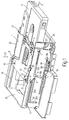
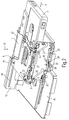
- FIGs 1 and 2 show a perspective view of parts of a loading mechanism of a drive of a magnetic tape cassette device in an eject position, in which a magnetic tape cassette 2 by the hand Operator can be removed.
- the loading mechanism has a cassette slot 1, into which the magnetic tape cassette 2 has been inserted in a horizontal loading direction 3.
- the cassette shaft 1 is shown in perspective view as an individual element in FIG. 10. At a distance, it has an upper plate 1a, a lower plate 1b, a side wall 1c extending in the horizontal loading direction 3 and a rear stop edge 1d against which the magnetic tape cassette 2 can be pushed by hand when inserted.
- the cassette shaft 1 has two U-shaped hinge openings 4 and 5 on the top plate 1a and a first pin 6 on the side wall 1c.
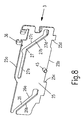
- a lift element 8 is provided, which is shown in FIG. 7 in a perspective view as a single element.
- This lift element 8 has a first pin 9, opposite a second pin 10, a third pin 11 and two lift approaches 13 and 14. These lift approaches 13 and 14 engage in the hinge openings 4 and 5 of the cassette shaft 1.
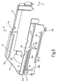
- a U-shaped frame 15, shown as a single element in FIG. 9, is provided, which has a rear wall 15a and two side walls 15b and 15c.
- a first guide slot 17 which extends in the horizontal loading direction 3
- a second guide slot 18 which extends in the horizontal loading direction 3.
- the side wall 15b of the frame 15 has a third guide slot 19 which is substantially L-shaped and has a horizontal part 19a extending in the horizontal loading direction 3 and a vertical part 19b extending substantially in a vertical loading direction 21, the vertical part 19b being curved.
- a fourth guide slot 20 which is essentially L-shaped and has a horizontal part 20a extending in the horizontal loading direction 3 and a vertical part 20b extending in the vertical loading direction 21.
- the frame 15 is arranged on a chassis plate 16 of the magnetic tape cassette device.
- the first pin 9 of the lift element 8 engages in the first guide slot 17 of the frame 15, the second pin 10 of the lift element 8 engages in the second guide slot 18 of the frame 15, and the third pin 11 of the lift element 8 engages in the third guide slot 19 of the frame 15 a.
- the first pin 6 of the cassette shaft 1 engages in the fourth guide slot 20 of the frame 15.
- the side wall 15c of the frame 15 has a support surface 22, on which an extension 23 of the cassette shaft 1 can slide in the horizontal loading direction 3.
- a first lift plate 25, shown as an individual element in FIG. 8, is provided, which has a first slot 26 and a second slot 27 which is inclined to the horizontal loading direction 3.
- the second slot 27 of the first lift plate 25 has a horizontal part 27a extending in the horizontal loading direction 3 and a part 27b extending inclined to the horizontal loading direction 3.
- the first pin 6 of the cassette shaft 1 engages in the slot 26 of the first lift plate 25, and the third pin 11 of the lift element 8 engages in the second slot 27.
- the first lift plate 25 has a guide pin 45 which is guided in a sixth guide opening 46 of the frame 15 which extends in the horizontal loading direction 3.
- the first lift plate 25 has an upper side 25a and a lower side 25b.
- the underside 25b of the lift plate 25 is slidably mounted on the chassis plate 16 in the horizontal loading direction 3.
- the first lift plate 25 can be moved back and forth in the horizontal loading direction 3 by a toothed rack 30, which is slidably mounted on the chassis plate 16 and can be driven in the horizontal loading direction 3 by a servo motor (not shown). If the first lift plate 25 is moved by the rack 30 in the horizontal loading direction 3, the rack 30 presses against an edge 25c of the first lift plate 25, the first lift plate 25 is moved by the rack 30 against the horizontal loading direction 3 moves, the rack 30 presses against an edge 25d of the first lift plate 25.
- a blocking lever 32 is rotatably arranged about an axis of rotation 31 and is spring-loaded in the direction of an arrow 33.
- This blocking lever 32 locks the lift element 8 and the cassette shaft 1 with the frame 15, as long as the magnetic tape cassette 2 does not act on the blocking lever 32.
- an extension 34 of the blocking lever 32 engages in a locking opening 35 of the frame 15 as a result of the spring load. If the magnetic tape cassette 2 is pressed by the hand of an operator against the rear stop edge 1d of the cassette slot 1, the magnetic tape cassette 2 acts on the blocking lever 32 in such a way that it pivots against the direction of the arrow 33 and thereby the locking between the cassette slot 1 and the lift element 8 with the frame 15. It is thereby achieved that the loading mechanism can only be actuated when the magnetic tape cassette 2 has been completely inserted into the cassette shaft 1 by the hand of an operator.
- the first lift plate 25 has a lift plate hook 36 which is clamped to the first pin 9 of the lift element 8 by means of a schematically illustrated lift spring 37.
- a locking lever 38 which is spring-loaded in the direction of an arrow 40 is rotatably attached to the chassis plate 16 about an axis of rotation 39.
- FIG. 1 the loading mechanism is shown in the eject position with the complete frame 15, in Fig. 2 the rear wall 15a and the side wall 15b of the frame 15 are not shown in order to clarify the operation of the first lift plate 25.
- the magnetic tape cassette 2 is pushed so far into the cassette shaft 1 that it presses against the rear stop edge 1d of the cassette shaft 1 and thereby the blocking by means of the blocking lever 32 between the cassette shaft 1 and the lift element 8 the frame 15 is lifted.
- the magnetic tape cassette 2 is pushed further in the horizontal loading direction by an operator from this ejection position, so two operating cases can be distinguished:
- the magnetic tape cassette device is not switched on, it is not desirable, in order to avoid damage to the device, that the magnetic tape cassette 2 can be inserted into the magnetic tape cassette device by the hand of an operator beyond the eject position. This is ensured by means of the locking lever 38. If the magnetic tape cassette 2 is pressed into the magnetic tape cassette device beyond the eject position in the horizontal loading direction 3 when the magnetic tape cassette device is not switched on, then the first lift plate 25 is blocked in the horizontal loading direction 3 by the locking lever 38 in a manner not shown. If the magnetic tape cassette 2 is now pushed further in by the operator's hand in the horizontal loading direction 3, the cassette shaft 1 and the lift element 8 are also moved in the horizontal loading direction 3.
- the lift spring 37 is tensioned between the non-moving first lift plate 25 and the lift element 8 moving in the horizontal loading direction 3.
- the cassette shaft 1, the lift element 8 and the magnetic tape cassette 2 experience a force against the horizontal loading direction 3, and they are repeatedly moved into the eject position due to the spring force of the lift spring 37 when the operator no longer has any force on the magnetic tape cassette 2 is exercised.
- a switch (not shown), after a fixed displacement path, which may be of the order of approx. 4 mm, for example operated.
- a servo motor By actuating this switch, not shown, a servo motor, not shown, is switched on acts on the gear rack 30 via a gear chain (not shown) and moves it in the horizontal loading direction 3.
- the rack 30 moving in the horizontal loading direction 3 acts on the locking lever 38 in such a way that it rotates counter to the direction of the arrow 40 and releases the first lift plate 25 for movement in the horizontal loading direction 3.
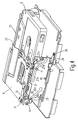
- the loading mechanism is first moved to an intermediate position, which is shown in FIGS. 3 and 4 in a perspective view.
- the loading mechanism is shown in the intermediate position with the complete frame 15, in Fig. 4, the rear wall 15a and the side wall 15b of the frame 15 are not shown to illustrate the operation of the first lift plate 25.
- the toothed rack 30 moves in the horizontal loading direction 3 during the transition between the eject position into the intermediate position, presses against the edge 25c of the first lift plate 25 and thereby takes this lift plate 25 from the eject position into the intermediate position.
- the first pin 6 of the cassette shaft 1 cannot slide down in the inclined first slot 26 of the first lift plate 25 because it is guided by the horizontal part 20a of the fourth guide slot 20 of the frame 15.
- the third pin 11 of the lift element 8 cannot slide down the inclined part 27b of the second slot 27 of the first lift plate 25 because it is simultaneously guided by the horizontal part 19a of the third guide slot 19 of the frame 15.
- the first pin 9 of the lifting element 8 slides along the transition from the ejection position into the intermediate position in the first guide slot 17 of the frame 15 extending in the horizontal loading direction 3, the second pin 10 of the lifting element 8 in the second guide slot 18 of the frame 15. In addition lies at the transition of the loading mechanism from the eject position to the intermediate position, the shoulder 23 of the cassette shaft 1 on the bearing surface 22 of the frame 15.
- the toothed rack 30, the first lift plate 25, the lift element 8 and the cassette shaft 1 with the magnetic tape cassette 2 are thus transferred in the horizontal loading direction from the eject position to the intermediate position shown in FIGS. 3 and 4 in a perspective view.
- the intermediate position the movement in the horizontal loading direction 3 of the lifting element 8 and the cassette shaft 1 is terminated in that the first pin 6 of the cassette shaft 1 presses against the frame 15 in the area 20c of the fourth guide slot 20 and the third pin 11 of the lifting element 8 in the area 19c of the third guide slot 19 presses against the frame 20.
- the first pin 9 and the second pin 10 of the lift element 8 press against the end regions 17a and 18a of the first guide slot 17 and the second guide slot 18, respectively.
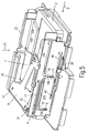
- the loading mechanism is subsequently transferred from the intermediate position into a playing position, which is shown in a perspective view in FIGS. 5 and 6.
- the entire frame 15 is shown in FIG. 5, the side wall 15b and the rear wall 15a of the frame 15 are not shown in FIG. 6 in order to clarify the functioning of the first lift plate 25.
- the edge 26a of the slot 26 of the first lift plate 25 exerts a force in the vertical loading direction 21 on the first pin 6 of the cassette shaft 1, as a result of which the first pin 6 of the cassette shaft 1 in the first slot 26 of the first lift plate 25 in the vertical direction Loading direction 21 slides down, the first pin 6 of the Cassette shaft 1 is simultaneously guided in the vertical part 20b of the fourth guide slot 20 of the frame 15.
- the lift element 8 performs a pure rotary movement about the first pin 9 and the second pin 10 of the lift element 8 during the transition between the intermediate position into the play position.
- the edge 27c of the second slot 27 of the first lift plate 25 exerts a force in the vertical loading direction 21 on the third pin 11 of the lift element 8, as a result of which the third pin 11 of the lift element 8 in the inclined section 27b of the second slot 27 of the first lift plate 25 slides down.
- the third pin 11 of the lift element 8 is simultaneously guided in the curved vertical part 19b of the third guide slot 19 of the frame 15.
- the magnetic tape cassette 2 with its winding openings 41 and 42 engages with the not shown winding plates of the magnetic tape cassette device, and the magnetic tape of the magnetic tape cassette can e.g. be guided past a magnetic head (not shown) for playback operation.
- the process described above takes place in the reverse manner.
- the first lift plate 25 is moved against the horizontal loading direction 3, which means that first lifting element 8 is rotated from the playing position into the intermediate position by means of a rotary movement about the first pin 9 or the second pin 10, and as a result the cassette shaft 1 is raised from the playing position into the intermediate position against the vertical loading direction 21.
- the first lift plate 25, driven by the toothed rack 30 pressing against the edge 25d of the first lift plate 25, the gear chain, not shown, and the servo motor, not shown, are transported against the horizontal loading direction.
- the first lift plate 25 acts on the cassette shaft 1 and the lift element 8 in such a way that these, together with the magnetic tape cassette 2, likewise move against the horizontal loading direction 3 from the intermediate position into the eject position.
- the forces to be applied by the servo motor by means of the gear chain (not shown) and the toothed rack 30 for driving the first lift plate 25 are particularly high during the transition from the playing position to the intermediate position, since the magnetic tape cassette 2 has to be raised from the playing position to the intermediate position against its gravity .
Landscapes
- Automatic Tape Cassette Changers (AREA)
Applications Claiming Priority (2)
| Application Number | Priority Date | Filing Date | Title |
|---|---|---|---|
| DE19609790 | 1996-03-13 | ||
| DE19609790A DE19609790A1 (de) | 1996-03-13 | 1996-03-13 | Lademechanismus |
Publications (3)
| Publication Number | Publication Date |
|---|---|
| EP0802532A2 true EP0802532A2 (fr) | 1997-10-22 |
| EP0802532A3 EP0802532A3 (fr) | 1998-11-04 |
| EP0802532B1 EP0802532B1 (fr) | 2001-11-28 |
Family
ID=7788114
Family Applications (1)
| Application Number | Title | Priority Date | Filing Date |
|---|---|---|---|
| EP97200667A Expired - Lifetime EP0802532B1 (fr) | 1996-03-13 | 1997-03-06 | Mécanisme de chargement de cassette à bande |
Country Status (5)
| Country | Link |
|---|---|
| EP (1) | EP0802532B1 (fr) |
| JP (1) | JP3980112B2 (fr) |
| KR (1) | KR100542413B1 (fr) |
| CN (1) | CN1133163C (fr) |
| DE (2) | DE19609790A1 (fr) |
Families Citing this family (1)
| Publication number | Priority date | Publication date | Assignee | Title |
|---|---|---|---|---|
| KR100717847B1 (ko) * | 2005-12-09 | 2007-05-14 | 한국전자통신연구원 | 시간 주파수 호핑 방식을 사용하는 다중대역 ofdm초광대역 시스템에서의 주파수 옵셋 추정 및 보상 방법과,그 장치 |
Family Cites Families (11)
| Publication number | Priority date | Publication date | Assignee | Title |
|---|---|---|---|---|
| JPS62231453A (ja) * | 1986-03-31 | 1987-10-12 | Clarion Co Ltd | カセツト・ロ−デイング機構 |
| US5136443A (en) * | 1987-11-20 | 1992-08-04 | Goldstar Co., Ltd. | Cassette loading apparatus for digital audio tape recorder |
| US5214548A (en) * | 1987-12-09 | 1993-05-25 | Mitsubishi Denki Kabushiki Kaisha | Tape cassette loading mechanism in tape player |
| DE3832672A1 (de) * | 1988-09-27 | 1990-03-29 | Philips Patentverwaltung | Magnetbandkassettengeraet mit einem zum abspielen von magnetbandkassetten dienenden laufwerk |
| DE3914789A1 (de) * | 1989-05-05 | 1990-11-08 | Philips Patentverwaltung | Magnetbandkassettengeraet mit einem zum abspielen von magnetbandkassetten dienenden laufwerk |
| EP0384511B1 (fr) * | 1989-02-15 | 1994-11-30 | Philips Patentverwaltung GmbH | Appareil à cassette à bande magnétique avec un dispositif d'entraînement pour la reproduction de cassettes à bande magnétique |
| US5189573A (en) * | 1989-02-15 | 1993-02-23 | U.S. Philips Corporation | Magnetic tape cassette apparatus with a drive mechanism which serves for playing magnetic tape cassettes |
| US5402405A (en) * | 1991-03-18 | 1995-03-28 | Sony Corporation | Cassette loading apparatus |
| DE4229754A1 (de) * | 1992-09-05 | 1994-03-10 | Philips Patentverwaltung | Magnetbandkassettengerät mit einem zum Abspielen von Magnetbandkassetten dienenden Laufwerk (Führung des Lademechanismus) |
| JPH0765462A (ja) * | 1993-08-30 | 1995-03-10 | Tanashin Denki Co | テープカセットのローディング装置 |
| JP2932908B2 (ja) * | 1993-11-16 | 1999-08-09 | 松下電器産業株式会社 | カセットローディング装置 |
-
1996
- 1996-03-13 DE DE19609790A patent/DE19609790A1/de not_active Withdrawn
-
1997
- 1997-03-06 EP EP97200667A patent/EP0802532B1/fr not_active Expired - Lifetime
- 1997-03-06 DE DE59705488T patent/DE59705488D1/de not_active Expired - Fee Related
- 1997-03-11 JP JP05622797A patent/JP3980112B2/ja not_active Expired - Lifetime
- 1997-03-12 KR KR1019970009023A patent/KR100542413B1/ko not_active Expired - Fee Related
- 1997-03-13 CN CN97111260A patent/CN1133163C/zh not_active Expired - Fee Related
Also Published As
| Publication number | Publication date |
|---|---|
| DE19609790A1 (de) | 1997-09-18 |
| EP0802532A3 (fr) | 1998-11-04 |
| JPH103715A (ja) | 1998-01-06 |
| KR100542413B1 (ko) | 2006-04-28 |
| CN1171596A (zh) | 1998-01-28 |
| EP0802532B1 (fr) | 2001-11-28 |
| JP3980112B2 (ja) | 2007-09-26 |
| CN1133163C (zh) | 2003-12-31 |
| DE59705488D1 (de) | 2002-01-10 |
| KR970067208A (ko) | 1997-10-13 |
Similar Documents
| Publication | Publication Date | Title |
|---|---|---|
| DE3241361C2 (fr) | ||
| DE3517004C2 (fr) | ||
| DE3785160T2 (de) | Anordnung zum verschieben des abtastkopfes eines optischen plattengeräts. | |
| DE3139333C2 (fr) | ||
| DE68924926T2 (de) | Plattenkassette. | |
| DE2952537A1 (de) | Lademechanismus fuer tonband- kassettengeraete | |
| DE4408120B4 (de) | Plattenabspielgerät | |
| DE4032834C2 (de) | Plattenabspielgerät | |
| DE69419633T2 (de) | Magazinplattenspieler mit umschaltbarer Antriebsvorrichtung | |
| DE3889862T2 (de) | Kassettenladegerät für Digital-Audio-Bandaufzeichnungsgerät. | |
| DE69120647T2 (de) | Plattenmagazinauswurfvorrichtung | |
| DE3719572C2 (fr) | ||
| CH666571A5 (de) | Magnetband-aufzeichnungs- und wiedergabegeraet. | |
| DE4326386A1 (de) | Diskabspielgerät-Mechanik | |
| DE3432831C1 (de) | Kassetten-Tonbandgeraet | |
| DE69220627T2 (de) | Ladegerät für Bandkassette und Platte | |
| DE60001372T2 (de) | Plattenwechslervorrichtung | |
| DE3943564C2 (de) | Plattenabspielgerät mit integriertem Plattenwechsler | |
| DE3332322C2 (fr) | ||
| DE69329995T2 (de) | Automatisches Lade-/Entladesystem für Bandkassette | |
| EP0802532B1 (fr) | Mécanisme de chargement de cassette à bande | |
| DE4102938A1 (de) | Disk-waehlvorrichtung | |
| DE2823226C2 (de) | Kassettenrecorder | |
| DE69013537T2 (de) | Kassetten-Lademechanismus eines Gerätes für magnetische Aufzeichnung und Wiedergabe. | |
| DE3710689A1 (de) | Kassetteneinlegemechanismus |
Legal Events
| Date | Code | Title | Description |
|---|---|---|---|
| PUAI | Public reference made under article 153(3) epc to a published international application that has entered the european phase |
Free format text: ORIGINAL CODE: 0009012 |
|
| AK | Designated contracting states |
Kind code of ref document: A2 Designated state(s): DE FR GB IT |
|
| RAP3 | Party data changed (applicant data changed or rights of an application transferred) |
Owner name: KONINKLIJKE PHILIPS ELECTRONICS N.V. Owner name: PHILIPS PATENTVERWALTUNG GMBH |
|
| PUAL | Search report despatched |
Free format text: ORIGINAL CODE: 0009013 |
|
| AK | Designated contracting states |
Kind code of ref document: A3 Designated state(s): DE FR GB IT |
|
| 17P | Request for examination filed |
Effective date: 19990504 |
|
| 17Q | First examination report despatched |
Effective date: 19990607 |
|
| RAP3 | Party data changed (applicant data changed or rights of an application transferred) |
Owner name: KONINKLIJKE PHILIPS ELECTRONICS N.V. Owner name: PHILIPS CORPORATE INTELLECTUAL PROPERTY GMBH |
|
| GRAG | Despatch of communication of intention to grant |
Free format text: ORIGINAL CODE: EPIDOS AGRA |
|
| GRAG | Despatch of communication of intention to grant |
Free format text: ORIGINAL CODE: EPIDOS AGRA |
|
| GRAH | Despatch of communication of intention to grant a patent |
Free format text: ORIGINAL CODE: EPIDOS IGRA |
|
| GRAH | Despatch of communication of intention to grant a patent |
Free format text: ORIGINAL CODE: EPIDOS IGRA |
|
| GRAA | (expected) grant |
Free format text: ORIGINAL CODE: 0009210 |
|
| AK | Designated contracting states |
Kind code of ref document: B1 Designated state(s): DE FR GB IT |
|
| PG25 | Lapsed in a contracting state [announced via postgrant information from national office to epo] |
Ref country code: IT Free format text: LAPSE BECAUSE OF FAILURE TO SUBMIT A TRANSLATION OF THE DESCRIPTION OR TO PAY THE FEE WITHIN THE PRESCRIBED TIME-LIMIT;WARNING: LAPSES OF ITALIAN PATENTS WITH EFFECTIVE DATE BEFORE 2007 MAY HAVE OCCURRED AT ANY TIME BEFORE 2007. THE CORRECT EFFECTIVE DATE MAY BE DIFFERENT FROM THE ONE RECORDED. Effective date: 20011128 |
|
| REG | Reference to a national code |
Ref country code: GB Ref legal event code: IF02 |
|
| REF | Corresponds to: |
Ref document number: 59705488 Country of ref document: DE Date of ref document: 20020110 |
|
| GBT | Gb: translation of ep patent filed (gb section 77(6)(a)/1977) |
Effective date: 20020206 |
|
| ET | Fr: translation filed | ||
| RAP2 | Party data changed (patent owner data changed or rights of a patent transferred) |
Owner name: KONINKLIJKE PHILIPS ELECTRONICS N.V. Owner name: PHILIPS CORPORATE INTELLECTUAL PROPERTY GMBH |
|
| PLBE | No opposition filed within time limit |
Free format text: ORIGINAL CODE: 0009261 |
|
| STAA | Information on the status of an ep patent application or granted ep patent |
Free format text: STATUS: NO OPPOSITION FILED WITHIN TIME LIMIT |
|
| REG | Reference to a national code |
Ref country code: GB Ref legal event code: 746 Effective date: 20021017 |
|
| 26N | No opposition filed |
Opponent name: KONINKLIJKE PHILIPS ELECTRONICS N.V. |
|
| REG | Reference to a national code |
Ref country code: FR Ref legal event code: D6 |
|
| PGFP | Annual fee paid to national office [announced via postgrant information from national office to epo] |
Ref country code: GB Payment date: 20070327 Year of fee payment: 11 |
|
| PGFP | Annual fee paid to national office [announced via postgrant information from national office to epo] |
Ref country code: DE Payment date: 20070516 Year of fee payment: 11 |
|
| PGFP | Annual fee paid to national office [announced via postgrant information from national office to epo] |
Ref country code: FR Payment date: 20070329 Year of fee payment: 11 |
|
| GBPC | Gb: european patent ceased through non-payment of renewal fee |
Effective date: 20080306 |
|
| REG | Reference to a national code |
Ref country code: FR Ref legal event code: ST Effective date: 20081125 |
|
| PG25 | Lapsed in a contracting state [announced via postgrant information from national office to epo] |
Ref country code: DE Free format text: LAPSE BECAUSE OF NON-PAYMENT OF DUE FEES Effective date: 20081001 |
|
| PG25 | Lapsed in a contracting state [announced via postgrant information from national office to epo] |
Ref country code: FR Free format text: LAPSE BECAUSE OF NON-PAYMENT OF DUE FEES Effective date: 20080331 |
|
| PG25 | Lapsed in a contracting state [announced via postgrant information from national office to epo] |
Ref country code: GB Free format text: LAPSE BECAUSE OF NON-PAYMENT OF DUE FEES Effective date: 20080306 |