EP0802576A1 - Couplage pour deux guides d'ondes de sections transversales différentes - Google Patents
Couplage pour deux guides d'ondes de sections transversales différentes Download PDFInfo
- Publication number
- EP0802576A1 EP0802576A1 EP97400752A EP97400752A EP0802576A1 EP 0802576 A1 EP0802576 A1 EP 0802576A1 EP 97400752 A EP97400752 A EP 97400752A EP 97400752 A EP97400752 A EP 97400752A EP 0802576 A1 EP0802576 A1 EP 0802576A1
- Authority
- EP
- European Patent Office
- Prior art keywords
- coupling
- stages
- wave
- types
- waveguide
- Prior art date
- Legal status (The legal status is an assumption and is not a legal conclusion. Google has not performed a legal analysis and makes no representation as to the accuracy of the status listed.)
- Granted
Links
- 230000008878 coupling Effects 0.000 title claims description 54
- 238000010168 coupling process Methods 0.000 title claims description 54
- 238000005859 coupling reaction Methods 0.000 title claims description 54
- 230000005540 biological transmission Effects 0.000 claims description 7
- 238000000034 method Methods 0.000 claims description 6
- 238000003801 milling Methods 0.000 claims description 4
- 238000004519 manufacturing process Methods 0.000 claims description 3
- 230000007480 spreading Effects 0.000 claims description 3
- 238000003892 spreading Methods 0.000 claims description 3
- 230000004323 axial length Effects 0.000 claims description 2
- 238000005266 casting Methods 0.000 claims 1
- 238000004070 electrodeposition Methods 0.000 claims 1
- 230000000644 propagated effect Effects 0.000 abstract description 4
- 230000037431 insertion Effects 0.000 abstract 1
- 238000003780 insertion Methods 0.000 abstract 1
- 230000008859 change Effects 0.000 description 3
- 238000004458 analytical method Methods 0.000 description 2
- 238000004364 calculation method Methods 0.000 description 2
- 230000018109 developmental process Effects 0.000 description 2
- 230000006978 adaptation Effects 0.000 description 1
- 230000008901 benefit Effects 0.000 description 1
- 238000010586 diagram Methods 0.000 description 1
- 238000009826 distribution Methods 0.000 description 1
- 230000000694 effects Effects 0.000 description 1
- 238000005516 engineering process Methods 0.000 description 1
- 230000005284 excitation Effects 0.000 description 1
- 230000001939 inductive effect Effects 0.000 description 1
- 238000005457 optimization Methods 0.000 description 1
- 230000008054 signal transmission Effects 0.000 description 1
- 230000009466 transformation Effects 0.000 description 1
- 230000007704 transition Effects 0.000 description 1
Images
Classifications
-
- H—ELECTRICITY
- H01—ELECTRIC ELEMENTS
- H01P—WAVEGUIDES; RESONATORS, LINES, OR OTHER DEVICES OF THE WAVEGUIDE TYPE
- H01P5/00—Coupling devices of the waveguide type
- H01P5/08—Coupling devices of the waveguide type for linking dissimilar lines or devices
- H01P5/082—Transitions between hollow waveguides of different shape, e.g. between a rectangular and a circular waveguide
Definitions
- the invention relates to a coupling for two electromagnetic waveguides with different cross-sectional shapes, which has steps arranged in the axial direction one behind the other with a substantially rectangular cross-section and rounded corners and different clear width, in which a low-reflection transmission of the wave types intended for signal guidance takes place (EP 0 145 292 A2).
- Such a coupling also referred to as a “transition”
- the cross sections of the two waveguides are basically arbitrary. For example, they can be elliptical, rectangular, square or round.
- a stepped clutch according to EP 0 145 292 A2 mentioned at the beginning is shorter.
- the use of this known coupling with an abrupt change in the cross-sectional geometry is expressly limited to frequency ranges in which only the corresponding fundamental wave may be propagated both in the two waveguides to be connected and in the coupling itself.
- the cross sections of the individual stages of the coupling are chosen so that other types of shaft are not capable of spreading.
- This known clutch is therefore limited to single-mode operation. It is used exclusively for the transmission of the respective basic modes of the waveguide to be connected. It is also assumed that the individual stages expand or contract in the same direction from one end of the clutch to the other, so that the cut-off frequency of the basic mode changes monotonously within the clutch.
- the coupling is only intended for the connection of a rectangular with an elliptical waveguide.
- the invention has for its object to develop the above-described device so that it can be used with a simple structure without restrictions for the connection of any waveguide and for any signal-carrying wave types.
- “Expandable” in the sense of the invention means that due to the dimensioning of the coupling basically all possible shaft types could or may spread. In contrast to the known coupling described at the beginning, no measures have been taken to prevent the spreadability of any type of shaft.
- the coupling used in this device is simple and easy to manufacture. It can be made from one part, into which the individual steps are milled, for example.
- the diameter of the milling cutter is appropriately and deliberately chosen so that the radii of the rounded corners are taken into account when dimensioning the steps.
- the coupling is suitable for connecting waveguides with very different cross sections with minimal loss of power. It is not restricted to any specific cross-sectional shape of the waveguide to be connected.
- the wave types provided for signal routing in the waveguides to be connected can either be of the basic wave type or correspond to a higher wave type. There is also the possibility that the basic wave type is used in one waveguide and a higher wave type is used for signal routing in the other waveguide.
- the coupling ensures the transformation of the shaft types in both transmission directions.
- the coupling can in particular also be used for waveguides in which several modes can be propagated.
- the coupling can thus be used to advantage to connect waveguides that are used in so-called overmodulated and therefore very low-loss frequency ranges.
- the coupling also allows the connection of a waveguide, which is operated in the single-mode frequency range and is therefore comparatively small, to an overmodified waveguide, in which several modes can propagate and which therefore has a comparatively large cross section.
- the electromagnetic properties of the same are recorded in their entirety. Their knowledge is used to manufacture the coupling.
- the couplings of the respective shaft types that occur at the discontinuities within the coupling (steps) and at the connection points to the connected waveguides are fully taken into account.
- the shaft types of all stages of the coupling involved and also that of the waveguide to be connected must be known.
- knowledge of the field distribution of the eigenmodes of rectangular waveguides with rounded corners is required. This includes both propagable wave types that contribute to the active power transport, as well as wave types that are not capable of propagation, since the operating frequency is below the respective limit frequency of the wave types.
- Such modes do not transport active power, but store inductive and capacitive reactive energy and are required in particular to describe the stray fields that form directly at the jump points and influence the behavior of the signal-carrying wave type.
- the coupling can also be used for the targeted excitation of several wave types, in order to feed, for example, antennas with their superimposition, which should have special directional characteristics.
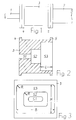
- Fig. 1 shows a schematic representation of a connection point between two waveguides with a coupling according to the invention.
- Fig. 2 shows a cross section through the clutch in an enlarged view.
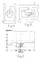
- Fig. 6 is a diagram for the reflection factor over frequency.
- Two electromagnetic waveguides 1 and 2 are connected to each other by a coupling 3 with little reflection.
- the waveguides 1 and 2 have very different dimensions.
- the waveguide 1 has, for example, a rectangular cross section, while the waveguide 2 is, for example, elliptical, with a much larger clear cross-sectional area than the waveguide 1.
- the coupling 3 has three stages S1, S2 and S3 in its clear cross section.
- the clear dimensions of the stages S1 to S3 can change in the same direction as shown in FIG. 3 from one end of the coupling 3 to its other end, so that at one end the smaller waveguide 1 and at the other end the larger waveguide 2 can be connected with little reflection.
- the stages S1 to S3 can also overlap each other according to FIG. 4.
- the abrupt change in the limit frequency of the wave types provided for signal routing, given by stages S1 to S3 can then fall from one end of the coupling and rise again or vice versa. Whether such overlaps occur depends on the operating frequency range and the respective cross-sectional shape and size of the waveguide to be connected and is decided in the respective application.
- connection of the waveguide to be connected is clear and must not be interchanged, since the coupling is asymmetrical in the axial direction. 5
- the axes of the individual stages S1 to S3 can also be offset from one another by a distance V, both in the horizontal and in the vertical direction.
- the clutch 3 is made in one piece. It can be connected to the waveguides 1 and 2 via flanges 4 and 5. Steps S1 to S3 can be produced, for example, using a milling cutter. Each of the levels S1 to S3 then has an iw rectangular clear cross section with rounded corners. The radius of the corners is determined by the diameter of the milling cutter used. It is only limited by the height and width of the individual steps.
- Height H, width B and the axial length L of the steps S1 to S3 and the radius R of their rounded corners are dimensioned such that, apart from the signal-carrying wave type, all other wave types are damped in such a way that they do not spread in the waveguides 1 and 2 and that negligibly little energy is withdrawn from the signal-carrying wave type through the coupling with other wave types.
- the undesired wave types are damped by superimposing the multiple reflections and transmissions of the wave types not intended for signal guidance on the discontinuities.
- several wave types are "capable of propagation" in accordance with the above explanation in the frequency range to be transmitted.
- the establishment of basic mechanical properties of the coupling 3 can be carried out in accordance with the frequency range to be transmitted and the required adaptation of the signal-carrying shaft types based on experience. This relates i. w. on the number of required stages of the coupling 3, the choice of the respective roundings and on the possibility of overlapping individual stages of the coupling 3 or the outer stages of the coupling 3 with the connected waveguides 1 and 2.
- a field theoretical analysis can be carried out using a digital computer, which analyzes the electromagnetic couplings of all wave types and in particular their effects on the reflection and transmission behavior of the signal-carrying wave types of the connected waveguides 1 and 2 completely detected.
- This analysis can e.g. B. with the help of the so-called mutual orthogonal series development. Due to the requirement for the continuity of the tangential electric and magnetic fields at each discontinuity of the coupling 3, the couplings of the shaft types are calculated in this method, taking into account all required eigenmodes of a rectangular waveguide with rounded corners.
- the electrical properties of coupling 3 can be optimized by targeted variation of the mechanical parameters - height H, width B, length L, rounding radius R, offset V of stages S1 to S3 in the transverse plane .
- the number of required stages of the coupling 3 depends mainly on the cross sections of the waveguide to be connected, on the required frequency bandwidth and on the electromagnetic requirements within the selected frequency range. This relates, for example, to the reflection and transmission factor of the signal-carrying wave types.
- a coupling was produced between a rectangular waveguide with a cross section of 10.67 mm x 4.32 mm and an elliptical waveguide, the main axes of which were dimensioned at 25.0 mm and 15.3 mm, respectively.
- the cross-sectional area of the rectangular waveguide is 6.5 times smaller than that of the elliptical waveguide.
- the clutch has three stages, which are arranged axially symmetrical to each other.
- the task of the coupling is the low-reflection adjustment of the basic modes H 10 of the rectangular waveguide and H cell of the elliptical waveguide in the frequency range 17.7 GHz to 19.7 GHz.
- 4 shows the measured (solid line) and the calculated (dashed line) reflection factor in the frequency range from 17.0 to 20.0 GHz.
- the reflection factor is ⁇ -34dB.
Landscapes
- Waveguides (AREA)
- Control Of Motors That Do Not Use Commutators (AREA)
Applications Claiming Priority (2)
| Application Number | Priority Date | Filing Date | Title |
|---|---|---|---|
| DE19615854A DE19615854C1 (de) | 1996-04-20 | 1996-04-20 | Verfahren zur Herstellung einer Kupplung für das Verbinden zweier elektromagnetischer Hohlleiter |
| DE19615854 | 1996-04-20 |
Publications (2)
| Publication Number | Publication Date |
|---|---|
| EP0802576A1 true EP0802576A1 (fr) | 1997-10-22 |
| EP0802576B1 EP0802576B1 (fr) | 2001-08-01 |
Family
ID=7791991
Family Applications (1)
| Application Number | Title | Priority Date | Filing Date |
|---|---|---|---|
| EP97400752A Expired - Lifetime EP0802576B1 (fr) | 1996-04-20 | 1997-04-01 | Couplage pour deux guides d'ondes de sections transversales différentes |
Country Status (5)
| Country | Link |
|---|---|
| US (1) | US5886588A (fr) |
| EP (1) | EP0802576B1 (fr) |
| AU (1) | AU708582B2 (fr) |
| BR (1) | BR9701847A (fr) |
| DE (2) | DE19615854C1 (fr) |
Cited By (1)
| Publication number | Priority date | Publication date | Assignee | Title |
|---|---|---|---|---|
| EP1933412A3 (fr) * | 2006-12-12 | 2008-12-17 | Andrew Corporation | Transition de guide d'onde et procédé de formation de composants |
Families Citing this family (7)
| Publication number | Priority date | Publication date | Assignee | Title |
|---|---|---|---|---|
| EP1233469A3 (fr) * | 2001-01-26 | 2003-07-30 | Spinner GmbH Elektrotechnische Fabrik | Armature pour guides d'ondes |
| US6583693B2 (en) | 2001-08-07 | 2003-06-24 | Andrew Corporation | Method of and apparatus for connecting waveguides |
| US7068121B2 (en) * | 2003-06-30 | 2006-06-27 | Tyco Technology Resources | Apparatus for signal transitioning from a device to a waveguide |
| DE102009026433A1 (de) * | 2009-05-25 | 2010-12-09 | Endress + Hauser Gmbh + Co. Kg | Anordnung zur Füllstandsmessung mit einem mit Mikrowellen arbeitenden Füllstandsmessgerät |
| US8816791B2 (en) * | 2010-09-28 | 2014-08-26 | Aviat U.S., Inc. | Systems and methods of a rectangular-to-circular waveguide transition |
| JP6526509B2 (ja) * | 2015-07-23 | 2019-06-05 | 株式会社東芝 | 導波管ベンドおよび無線機器 |
| CN115441141B (zh) * | 2022-10-17 | 2023-04-25 | 北京星英联微波科技有限责任公司 | 阶梯扭波导 |
Citations (7)
| Publication number | Priority date | Publication date | Assignee | Title |
|---|---|---|---|---|
| GB842344A (en) * | 1959-03-12 | 1960-07-27 | Standard Telephones Cables Ltd | Electrical waveguide junction arrangement |
| GB850992A (en) * | 1958-09-11 | 1960-10-12 | Standard Telephones Cables Ltd | Electrical h.f. waveguide junction between cylindrical guides of unlike diameters |
| US3019399A (en) * | 1959-03-06 | 1962-01-30 | Microwave Ass | Circular waveguide diameter transformer |
| US3686589A (en) * | 1969-09-23 | 1972-08-22 | Georg Spinner | Waveguide transition |
| US3818383A (en) * | 1973-02-27 | 1974-06-18 | Andrew Corp | Elliptical-to-rectangular waveguide transition |
| EP0145292A2 (fr) * | 1983-11-22 | 1985-06-19 | Andrew A.G. | Guide d'onde rectangulaire à élliptique |
| US4906951A (en) * | 1989-02-15 | 1990-03-06 | United States Department Of Energy | Birefringent corrugated waveguide |
Family Cites Families (5)
| Publication number | Priority date | Publication date | Assignee | Title |
|---|---|---|---|---|
| GB591667A (en) * | 1942-03-31 | 1947-08-25 | Sperry Gyroscope Co Inc | Improvements in or relating to impedance transformers for wave guides |
| NL212773A (fr) * | 1956-01-26 | |||
| US3336543A (en) * | 1965-06-07 | 1967-08-15 | Andrew Corp | Elliptical waveguide connector |
| JPS55101380A (en) * | 1979-01-20 | 1980-08-02 | Matsushita Electric Industrial Co Ltd | Driver for automatically clamping screw |
| US4642585A (en) * | 1985-01-30 | 1987-02-10 | Andrew Corporation | Superelliptical waveguide connection |
-
1996
- 1996-04-20 DE DE19615854A patent/DE19615854C1/de not_active Expired - Fee Related
-
1997
- 1997-04-01 DE DE59704165T patent/DE59704165D1/de not_active Expired - Lifetime
- 1997-04-01 EP EP97400752A patent/EP0802576B1/fr not_active Expired - Lifetime
- 1997-04-17 US US08/840,888 patent/US5886588A/en not_active Expired - Lifetime
- 1997-04-18 BR BR9701847A patent/BR9701847A/pt active Search and Examination
- 1997-04-18 AU AU18961/97A patent/AU708582B2/en not_active Ceased
Patent Citations (7)
| Publication number | Priority date | Publication date | Assignee | Title |
|---|---|---|---|---|
| GB850992A (en) * | 1958-09-11 | 1960-10-12 | Standard Telephones Cables Ltd | Electrical h.f. waveguide junction between cylindrical guides of unlike diameters |
| US3019399A (en) * | 1959-03-06 | 1962-01-30 | Microwave Ass | Circular waveguide diameter transformer |
| GB842344A (en) * | 1959-03-12 | 1960-07-27 | Standard Telephones Cables Ltd | Electrical waveguide junction arrangement |
| US3686589A (en) * | 1969-09-23 | 1972-08-22 | Georg Spinner | Waveguide transition |
| US3818383A (en) * | 1973-02-27 | 1974-06-18 | Andrew Corp | Elliptical-to-rectangular waveguide transition |
| EP0145292A2 (fr) * | 1983-11-22 | 1985-06-19 | Andrew A.G. | Guide d'onde rectangulaire à élliptique |
| US4906951A (en) * | 1989-02-15 | 1990-03-06 | United States Department Of Energy | Birefringent corrugated waveguide |
Cited By (2)
| Publication number | Priority date | Publication date | Assignee | Title |
|---|---|---|---|---|
| EP1933412A3 (fr) * | 2006-12-12 | 2008-12-17 | Andrew Corporation | Transition de guide d'onde et procédé de formation de composants |
| US7893789B2 (en) | 2006-12-12 | 2011-02-22 | Andrew Llc | Waveguide transitions and method of forming components |
Also Published As
| Publication number | Publication date |
|---|---|
| BR9701847A (pt) | 1998-09-08 |
| DE19615854C1 (de) | 1997-11-20 |
| AU1896197A (en) | 1997-10-30 |
| EP0802576B1 (fr) | 2001-08-01 |
| DE59704165D1 (de) | 2001-09-06 |
| US5886588A (en) | 1999-03-23 |
| AU708582B2 (en) | 1999-08-05 |
Similar Documents
| Publication | Publication Date | Title |
|---|---|---|
| DE2632606C2 (de) | Wellentypkoppler | |
| DE69013779T2 (de) | Hohlleiter-Speisenetzwerk für Gruppenantennen. | |
| DE2000065A1 (de) | Schaltungen,die Phasenschieberkoppler verwenden | |
| DE3706965C2 (fr) | ||
| DE2408610C3 (de) | Hornstrahler | |
| DE1021913B (de) | Kopplungsanordnung fuer breitbandigen Energieuebergang | |
| DE2255207A1 (de) | Anordnung zum ableiten des fehlersignals in einem system zum selbsttaetigen nachfuehren einer mikrowellenantenne | |
| DE19615854C1 (de) | Verfahren zur Herstellung einer Kupplung für das Verbinden zweier elektromagnetischer Hohlleiter | |
| EP0973227B1 (fr) | Résonateur annulaire à double mode | |
| EP1223638B1 (fr) | Réseau d'antennes | |
| DE69216299T2 (de) | Richtkoppleroptische Vorrichtung und Steuerverfahren dafür | |
| DE68918426T2 (de) | Doppelfrequenz strahlende Vorrichtung. | |
| EP1266423B1 (fr) | Resonateur a cavite a frequence de resonance reglable | |
| DE2842576C2 (de) | Polarisationsweiche | |
| EP2553757B1 (fr) | Structure de conducteurs coaxiaux | |
| DE2828047B1 (de) | Frequenzabhaengiges Koppelsystem | |
| EP1206812B1 (fr) | Adaptateur de guide d'ondes | |
| DE68915134T2 (de) | Mikrowellen-Bandpassfilter in Kammleitungsform. | |
| DE2642448B2 (de) | Hochfrequenz-Wellentypwandler | |
| DE10256263B4 (de) | Integriertes optisches Bauteil mit der Funktion eines Polarisations-Demultiplexers | |
| EP0419892B1 (fr) | Filtre de polarisation aux micro-ondes | |
| DE2508379A1 (de) | Filtereinrichtung unter verwendung von akustischen oberflaechenwellen | |
| DE2102554C3 (de) | Richtungskoppler | |
| EP0263560B1 (fr) | Coupleur optique en étoile | |
| DE1541393A1 (de) | Breitband-Hybride |
Legal Events
| Date | Code | Title | Description |
|---|---|---|---|
| PUAI | Public reference made under article 153(3) epc to a published international application that has entered the european phase |
Free format text: ORIGINAL CODE: 0009012 |
|
| 17P | Request for examination filed |
Effective date: 19970805 |
|
| AK | Designated contracting states |
Kind code of ref document: A1 Designated state(s): CH DE FR GB IT LI |
|
| RAP1 | Party data changed (applicant data changed or rights of an application transferred) |
Owner name: ALCATEL |
|
| GRAG | Despatch of communication of intention to grant |
Free format text: ORIGINAL CODE: EPIDOS AGRA |
|
| 17Q | First examination report despatched |
Effective date: 20001011 |
|
| GRAG | Despatch of communication of intention to grant |
Free format text: ORIGINAL CODE: EPIDOS AGRA |
|
| GRAH | Despatch of communication of intention to grant a patent |
Free format text: ORIGINAL CODE: EPIDOS IGRA |
|
| GRAH | Despatch of communication of intention to grant a patent |
Free format text: ORIGINAL CODE: EPIDOS IGRA |
|
| GRAA | (expected) grant |
Free format text: ORIGINAL CODE: 0009210 |
|
| AK | Designated contracting states |
Kind code of ref document: B1 Designated state(s): CH DE FR GB IT LI |
|
| ITF | It: translation for a ep patent filed | ||
| REG | Reference to a national code |
Ref country code: CH Ref legal event code: EP |
|
| GBT | Gb: translation of ep patent filed (gb section 77(6)(a)/1977) |
Effective date: 20010801 |
|
| REG | Reference to a national code |
Ref country code: CH Ref legal event code: NV Representative=s name: CABINET ROLAND NITHARDT CONSEILS EN PROPRIETE INDU |
|
| REF | Corresponds to: |
Ref document number: 59704165 Country of ref document: DE Date of ref document: 20010906 |
|
| ET | Fr: translation filed | ||
| REG | Reference to a national code |
Ref country code: GB Ref legal event code: IF02 |
|
| PG25 | Lapsed in a contracting state [announced via postgrant information from national office to epo] |
Ref country code: LI Free format text: LAPSE BECAUSE OF NON-PAYMENT OF DUE FEES Effective date: 20020430 Ref country code: CH Free format text: LAPSE BECAUSE OF NON-PAYMENT OF DUE FEES Effective date: 20020430 |
|
| PLBE | No opposition filed within time limit |
Free format text: ORIGINAL CODE: 0009261 |
|
| STAA | Information on the status of an ep patent application or granted ep patent |
Free format text: STATUS: NO OPPOSITION FILED WITHIN TIME LIMIT |
|
| 26N | No opposition filed | ||
| REG | Reference to a national code |
Ref country code: CH Ref legal event code: PL |
|
| PGFP | Annual fee paid to national office [announced via postgrant information from national office to epo] |
Ref country code: IT Payment date: 20060430 Year of fee payment: 10 |
|
| PG25 | Lapsed in a contracting state [announced via postgrant information from national office to epo] |
Ref country code: IT Free format text: LAPSE BECAUSE OF NON-PAYMENT OF DUE FEES Effective date: 20070401 |
|
| REG | Reference to a national code |
Ref country code: FR Ref legal event code: GC Effective date: 20140717 |
|
| REG | Reference to a national code |
Ref country code: FR Ref legal event code: RG Effective date: 20141016 |
|
| REG | Reference to a national code |
Ref country code: FR Ref legal event code: PLFP Year of fee payment: 19 |
|
| PGFP | Annual fee paid to national office [announced via postgrant information from national office to epo] |
Ref country code: GB Payment date: 20150420 Year of fee payment: 19 Ref country code: DE Payment date: 20150421 Year of fee payment: 19 |
|
| PGFP | Annual fee paid to national office [announced via postgrant information from national office to epo] |
Ref country code: FR Payment date: 20150421 Year of fee payment: 19 |
|
| REG | Reference to a national code |
Ref country code: DE Ref legal event code: R119 Ref document number: 59704165 Country of ref document: DE |
|
| GBPC | Gb: european patent ceased through non-payment of renewal fee |
Effective date: 20160401 |
|
| REG | Reference to a national code |
Ref country code: FR Ref legal event code: ST Effective date: 20161230 |
|
| PG25 | Lapsed in a contracting state [announced via postgrant information from national office to epo] |
Ref country code: FR Free format text: LAPSE BECAUSE OF NON-PAYMENT OF DUE FEES Effective date: 20160502 Ref country code: DE Free format text: LAPSE BECAUSE OF NON-PAYMENT OF DUE FEES Effective date: 20161101 Ref country code: GB Free format text: LAPSE BECAUSE OF NON-PAYMENT OF DUE FEES Effective date: 20160401 |