EP0802595B1 - Tableau de distribution avec un chassis - Google Patents
Tableau de distribution avec un chassis Download PDFInfo
- Publication number
- EP0802595B1 EP0802595B1 EP97106219A EP97106219A EP0802595B1 EP 0802595 B1 EP0802595 B1 EP 0802595B1 EP 97106219 A EP97106219 A EP 97106219A EP 97106219 A EP97106219 A EP 97106219A EP 0802595 B1 EP0802595 B1 EP 0802595B1
- Authority
- EP
- European Patent Office
- Prior art keywords
- chassis
- toggle
- nut piece
- threaded nut
- accordance
- Prior art date
- Legal status (The legal status is an assumption and is not a legal conclusion. Google has not performed a legal analysis and makes no representation as to the accuracy of the status listed.)
- Expired - Lifetime
Links
- 238000006073 displacement reaction Methods 0.000 claims 1
- 210000003127 knee Anatomy 0.000 description 7
- 210000002414 leg Anatomy 0.000 description 7
- 238000005192 partition Methods 0.000 description 6
- 230000013011 mating Effects 0.000 description 5
- 239000004020 conductor Substances 0.000 description 2
- 230000008878 coupling Effects 0.000 description 2
- 238000010168 coupling process Methods 0.000 description 2
- 238000005859 coupling reaction Methods 0.000 description 2
- 210000000629 knee joint Anatomy 0.000 description 2
- 238000006243 chemical reaction Methods 0.000 description 1
- 230000007423 decrease Effects 0.000 description 1
- 230000001419 dependent effect Effects 0.000 description 1
- 238000010586 diagram Methods 0.000 description 1
- 230000000694 effects Effects 0.000 description 1
- 230000002996 emotional effect Effects 0.000 description 1
- 238000005516 engineering process Methods 0.000 description 1
- 238000000926 separation method Methods 0.000 description 1
Images
Classifications
-
- H—ELECTRICITY
- H02—GENERATION; CONVERSION OR DISTRIBUTION OF ELECTRIC POWER
- H02B—BOARDS, SUBSTATIONS OR SWITCHING ARRANGEMENTS FOR THE SUPPLY OR DISTRIBUTION OF ELECTRIC POWER
- H02B11/00—Switchgear having carriage withdrawable for isolation
- H02B11/12—Switchgear having carriage withdrawable for isolation with isolation by horizontal withdrawal
- H02B11/127—Withdrawal mechanism
Definitions
- the invention relates to a control panel according to the preamble of first claim.
- a known panel of this type (DE 3812853 C1) has in rails running parallel to the depth of the housing on which a chassis with casters movably seated.
- the chassis carries three horizontally Switch poles arranged side by side, each of which two contact arms arranged vertically one above the other in the Project the housing depth freely.
- the chassis Switch poles and associated actuators formed trolley is with a horizontal Traverse provided on the front of the chassis is present and after manually inserting the switch carriage in the scaffold is locked with the latter. The arrangement is taken so that the contact arms are still at a distance of mating contacts arranged in the rear part of the scaffold stand.
- a threaded spindle is rotatable on the crossbar, however axially immovable, on the one with the switch carriage connected threaded nut piece is turned.
- the threaded spindle is accessible through the traverse and with a hand crank can be coupled, by means of which the threaded spindle can be rotated.
- the switch carriage under Support on the traverse further into the depth of the cubicle frame be moved until the contact arms with the assigned mating contacts in electrical Contact system.
- the upper contact arms reach through Breakthroughs in a vertical partition behind which the associated mating contacts connected to busbars are arranged.
- From US-A-5 459 293 is a panel with one in one Scaffold guided on parallel tracks, with known at least one switch provided chassis become.
- the chassis is one Coupled drive device, which is a threaded nut piece has, which is screwed onto a threaded spindle.
- the Threaded spindle is secured against axial adjustment and in a traverse fixed to the running rails rotatably mounted.
- the threaded spindle continues to run parallel to and in the middle between the runners.
- the Running rails are rigidly connected to the crossbar.
- a control panel has become known from DE 37 17 495 A1, in which the chassis over a in the direction of travel Chassis lever mechanism with two Toggle lever pairs is moved.
- the Threaded nut pieces are both on a threaded spindle has two opposing threaded section halves.
- the Pair of toggle levers are supported on the housing at one end of the control panel. At the other end, the knee levers are on Chassis articulated.
- Such a state of the Technology has the disadvantage that when the Threaded spindle for moving the chassis Threaded spindle changes its position.
- Another disadvantage of this Panel is that with relatively large travels a very long spindle is required as for each Thread nut piece only half the length of the threaded spindle Available.
- the present invention is therefore based on the object in a panel according to the preamble of the first Claim to take measures by which a reduction for moving and separating the contact arms and Counter contacts required torque on the threaded spindle is achieved.
- the threaded spindle should not be in its position change, so that the threaded spindle can also be easily used stationary motor can be driven.
- the threaded spindle should also be easily used stationary motor can be driven.
- a configuration of a switch panel according to the invention is achieved through the use of a toggle mechanism, which during the retraction of the chassis from a kink in axially aligned stretched position of his pair of toggle levers will be necessary for moving the contacts together high feed force is applied when the chassis largely retracted into his working position Contacts are to be brought into engagement.
- the occurring in operation on the Switching car acting reaction forces especially in the event of a short circuit no longer act on the threaded spindle, but via the respective straight pair of toggle levers directly from Chassis on the traverse or related components and from the crossbeam to the frame supporting the counter contacts be transmitted.
- toggle lever pairs are provided.
- Threaded spindle parallel to and in the middle between those intended for the chassis Running tracks to an exact parallel shift over to ensure the route and in order to ensure that it also occurs during operation To be able to absorb current impulses without tipping.
- the Running rails in particular rigidly connected to the crossbar be, the traverse together with the rails and a base plate bearing the same as a slide-in cassette can be formed together with the mounted thereon Push the switching carriage into the scaffolding and lock it in place is.
- the chassis can be designed with a low height be and the unit from cassette and switch carriage above of a cable room can be inserted into the scaffold.
- the pivot point of the respective pair of toggle levers on the switching carriage lies in Direction of the housing depth, in particular further from the traverse removed as the fixed pivot point.
- the Fixed articulation point also in the middle area between the End positions of the threaded nut piece must be arranged.
- the fixed articulation point can be at a greater radial distance from the lead screw as the pivot point of each Pair of toggle levers on the chassis. Also the toggle joint point in the direction of retraction of the chassis before each Threaded nut piece. This results in a compact structure of the Toggle mechanism. The inclination in particular contributes to this of the toggle lever pairs in their extended position.
- the handlebar lever approximately L-shaped and with its short leg on the threaded nut piece and with its long leg on the knee joint so that the long leg in the end position of the threaded nut piece extended shift carriage parallel to the longitudinal axis of the threaded spindle and when the switch carriage is retracted approximately perpendicular to Extension axis of the respective pair of toggle levers.
- their fixed articulation point is particularly at the associated running rail, which is U-shaped in cross section is and therefore absorb high mechanical loads can.
- the fixed articulation point is preferably so placed that between two wheels of the chassis sits, which are assigned to the relevant track.
- the distance between the wheels is larger than that with Length of the retractable or Extension path of the switch carriage.
- the wheels can therefore in normal entry and exit operations not against the fixed Hinge points or the knee levers connected to them, especially these toggle levers when moving out, i.e. when adjusting of the switching carriage, in the electrical disconnected position from their inclined in an approximately vertical position with respect to the Running rails can be adjusted.
- the drive of the threaded spindle can be plugged onto the end on the truss side Hand crank or via a gearbox by an electric motor respectively.
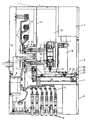
- a control panel that is particularly suitable for use in medium-voltage networks has a cuboid scaffold (1) on, the front in the lower area and in the middle Area each a door (2,3) and in the upper area a control box (4).
- a cable room (5) provided with cables (6) inserted from below, which via Busbars per phase with one on the back (8) of the Scaffold (1) arranged current transformer (9) and one below arranged voltage converter (10) are electrically connected.
- the current conductors (7) lead from them to the current transformers (9) arranged counter contacts (11), which over insulating sleeves (12) on a partition (13) connected to the frame (1) are connected.
- connection of the Circuit breakers (16) With the connections of the Circuit breakers (16) are arranged at a distance in height Contact arms (17) connected to the scaffold depth protrude and in the shown retracted position of the Circuit breaker (16) in plug contact connection with the stand-tight counter contacts (11).
- the circuit breakers (16) sit on a drive box (18), of which an operating rod (19) to the movable contact pin (20) of the circuit breaker leads and via the on or off the circuit breaker (16).
- the drive box (18) is mounted on a chassis (21) which in via wheels (22) Running rails (23) is guided, which from the Area of the door (3) into the scaffold depth towards the partition (13) run parallel to each other.
- the running rails (23) sit on a base plate (24.1) or a trough-shaped for reasons of stability designed slide-in cassette (24), which after the Inserting the from the cassette (24), the chassis (21), the drive box (18) and the circuit breaker (16) formed switching carriage unit by means of a horizontal extending traverse (25) is releasably locked to the scaffold (1).
- the chassis (21) with the drive box (18) and the circuit breakers (16) in an extended position, in which the drive box facing the door (3) close to the Door (3) stands and the plug connections (11, 17) through the contact arms (17) adjusted correspondingly far to the door (3) are separated.
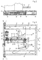
- a drive device is provided that a Includes threaded spindle (26), which prevents axial adjustment secured in the crossmember (25) and rotatably mounted to the door (3) pointing coupling piece (27.) to attach one Has crank.
- toggle lever (31) for each pair of toggle levers is on the cassette (24) around a pivot point (35) pivotable, while the second toggle lever (31) of each pair of toggle levers pivotable about a pivot point (36) on the chassis (21) is attached.
- the articulation point (36) of the with the switching carriage connected toggle lever (31) of each toggle lever pair is further away from the traverse (25) as the fixed one at the Cassette (24) fixed articulation point (35) of the second toggle lever (31) each pair of toggle levers.
- the stationary one sits there Articulation point (35) in the middle area between the axial End positions of the threaded nut piece (29) and in a larger radial Distance from the threaded spindle (26) as the articulation point (36) of the respective toggle lever (31) of a pair of toggle levers on the driving. frame (21).
- the toggle lever pairs (31) are therefore in the extended position of the switching carriage (16,21) in a V-shaped assignment the upper representation shown in full lines in FIG. 3, while in the retracted position (according to Figure 1) the knee lever (31) of the two pairs of toggle levers axially over the pivot points (36,32,35) stretched position (Fig 3, lower dashed line).
- the toggle point (32) is located in the direction of retraction of the chassis (21) each in front of the threaded nut piece (29) with varying radial distance from the threaded spindle (26).
- the handlebar (33) is approximately L-shaped and with his shorter leg on the threaded nut piece (29) and with his longer leg articulated on the knee joint (32). It says shorter legs in the end position of the threaded nut piece (29) at least when the switching carriage is extended ( Figure 3, full lines) approximately vertical and the longer leg approximately parallel to the longitudinal axis of the threaded spindle (26).
- the retracted position of the chassis (21) corresponds to that with spring contact pieces equipped contact arms (17) of the circuit breaker (16) in contact with the fixed mating contacts (11) kick and put on it with considerable effort must be at the toggle joint points (32) with approximately extended toggle levers (31) only one relatively low force, due to mechanical friction overcome contact sliding resistance generated.
- the way is then to overcome the high frictional forces between the contacts when moving the chassis (21) from the retracted position only a correspondingly small one Torque on the threaded spindle (26) required because the retraction forces on the toggle joint (32) are very small, when the toggle lever pairs (31) come out of the extended position to be led back.
- the mirror-image arrangement of the toggle lever pairs (31) causes by working with the handlebars (33) and common threaded nut piece (29) an exact parallel guide the chassis (21) and in the extended position of the knee lever pairs (31) are those that occur during operation, from the current flow dependent impact forces on the extended pairs of toggle levers (31) introduced directly into the cassette (24) and thus from the threaded nut piece kept away. Otherwise, the threaded spindle (26) from opposite sides with identical Forces applied so that practically no stress on Bend occurs.
- the fixed articulation point (35) of the knee lever pairs (31) sits in particular on the associated running track (23), which due to its U-shaped cross-sectional design has high inherent rigidity and friction and current impulses with the chassis (21) retracted from the retractable pivot point (36 'according to FIG. 3 below) at least up to close to the Traverse (25) leads.
- the fixed pivot point (35) of the Pair of toggle levers (31) is between two of these rails (23) assigned wheels (22) of the chassis (21) intended.
- the distance between the fixed pivot point (35) and the impeller (22) to be rolled thereon is larger than the travel distance of the chassis still to be covered in each case (21).
Landscapes
- Engineering & Computer Science (AREA)
- Power Engineering (AREA)
- Transmission Devices (AREA)
- Fittings On The Vehicle Exterior For Carrying Loads, And Devices For Holding Or Mounting Articles (AREA)
- Invalid Beds And Related Equipment (AREA)
Claims (9)
- Poste de commutation comportant un chariot (21) qui est guidé pour pouvoir de déplacer dans un cadre (1) sur des rails de roulement (23), qui est équipé d'au moins un commutateur et qui est couplé avec un dispositif d'entraínement qui comporte une pièce formant écrou fileté (29) qui tourne sur une broche filetée (26) qui est montée à rotation, en étant assurée contre un déplacement axial, dans une traverse (25) qui est montée fixe par rapport aux rails de roulement (23), poste dans lequel la broche filetée (26) s'étend parallèlement aux rails de roulement (23) et au centre de ces dernières qui sont reliées de manière rigide à la traverse (25), caractérisé en ce que l'on prévoit un mécanisme à genouillère qui agit dans la direction de déplacement du chariot (21) et qui comporte au moins une genouillère (31) qui est en appui, de manière fixe, à une de ses extrémités, sur le chariot (21) et, à son autre extrémité, par rapport à la traverse (25) et qui est couplée, au point d'articulation de la genouillère (32), avec la pièce formant écrou fileté (29), par l'intermédiaire d'un levier à bielles (33), le levier à bielles (33) étant articulé avec possibilité de pivotement, d'une part, sur la pièce formant écrou fileté (29) et, d'autre part, sur le point d'articulation de la genouillère (32).
- Poste de commutation selon la revendication 1, caractérisé en ce que le mécanisme à genouillère comporte deux genouillères (31) et deux leviers à bielle (33) qui, à chaque fois, sont disposés avec une symétrie spéculaire par rapport à l'axe longitudinal de la broche filetée (26) dans un plan qui est parallèle au plan comprenant les rails de roulement (23).
- Poste de commutation selon la revendication 1 ou 2, caractérisé en ce que le point d'articulation (36) de la ou de chaque genouillère (31) est plus éloigné de la traverse (25) que ne l'est le point d'articulation fixe (35).
- Poste de commutation selon la revendication 3, caractérisé en ce que le point d'articulation fixe (35) de la genouillère (31) se trouve dans la zone médiane se trouvant entre les positions finales axiales de la pièce formant écrou fileté (29) et se trouve à une distance radiale par rapport à la broche filetée (26) plus grande que celle de la genouillère respective (31) se trouvant sur le chariot (21).
- Poste de commutation selon la revendication 1 et l'une quelconque des revendications suivantes, caractérisé en ce que le point d'articulation de la genouillère (32) se trouve, dans la direction de déplacement du chariot (21), à chaque fois, devant la pièce formant écrou fileté (29).
- Poste de commutation selon la revendication 1 et l'une quelconque des revendications suivantes, caractérisé en ce que les leviers articulés de chaque genouillère (31) se trouvent, dans la position finale de la pièce formant écrou fileté (29) dans laquelle le chariot (21) est rentré, en position d'extension l'un en face de l'autre.
- Poste de commutation selon la revendication 1 et l'une quelconque des revendications suivantes, caractérisé en ce que le levier à bielles (33) a sensiblement la forme d'un « L » et est articulé, par sa branche la plus courte, sur la pièce formant écrou fileté (29) et, par sa branche la plus longue, sur le point d'articulation de la genouillère (32) et en ce que, dans la position finale de la pièce formant écrou fileté (29) dans laquelle le chariot (21) est sorti, la branche la plus courte se trouve, pour le moins approximativement, verticale et la branche la plus longue se trouve approximativement parallèle à l'axe longitudinal de la broche filetée (26).
- Poste de commutation selon la revendication 1 et l'une quelconque des revendications suivantes, caractérisé en ce que le point d'articulation fixe (35) des genouillères (31) se trouve sur le rail de roulement (23) correspondant et entre deux roues de roulement (22) du chariot (21) qui sont associées à ce rail de roulement (23).
- Poste de commutation selon la revendication 1 et l'une quelconque des revendications suivantes, caractérisé en ce que la broche filetée (26) est en relation d'entraínement avec un moteur électrique (3).
Applications Claiming Priority (2)
| Application Number | Priority Date | Filing Date | Title |
|---|---|---|---|
| DE19615312 | 1996-04-18 | ||
| DE19615312A DE19615312A1 (de) | 1996-04-18 | 1996-04-18 | Schaltfeld mit einem Fahrgestell |
Publications (3)
| Publication Number | Publication Date |
|---|---|
| EP0802595A2 EP0802595A2 (fr) | 1997-10-22 |
| EP0802595A3 EP0802595A3 (fr) | 1998-08-12 |
| EP0802595B1 true EP0802595B1 (fr) | 2002-07-31 |
Family
ID=7791634
Family Applications (1)
| Application Number | Title | Priority Date | Filing Date |
|---|---|---|---|
| EP97106219A Expired - Lifetime EP0802595B1 (fr) | 1996-04-18 | 1997-04-16 | Tableau de distribution avec un chassis |
Country Status (3)
| Country | Link |
|---|---|
| EP (1) | EP0802595B1 (fr) |
| DE (2) | DE19615312A1 (fr) |
| ES (1) | ES2179975T3 (fr) |
Cited By (1)
| Publication number | Priority date | Publication date | Assignee | Title |
|---|---|---|---|---|
| US9595412B2 (en) | 2014-03-31 | 2017-03-14 | Schneider Electric Industries Sas | Control panel including solid-insulated plug-in connection |
Families Citing this family (5)
| Publication number | Priority date | Publication date | Assignee | Title |
|---|---|---|---|---|
| DE10010738B4 (de) * | 2000-03-04 | 2008-05-08 | Areva T&D Sa | Schaltfeld mit einem Fahrgestell |
| DE10040685C1 (de) * | 2000-08-19 | 2002-01-03 | Felten & Guilleaume Ag | Elektrisches Schaltgerät |
| DE20117583U1 (de) | 2001-10-22 | 2003-03-13 | Siemens AG, 80333 München | Verriegelungseinrichtung |
| DE102011006115B4 (de) | 2011-03-25 | 2014-01-30 | Schneider Electric Sachsenwerk Gmbh | Elektrische Schaltanlage, insbesondere Mittelspannungsschaltanlage |
| KR101640712B1 (ko) * | 2015-04-20 | 2016-07-19 | 엘에스산전 주식회사 | 진공차단기 |
Family Cites Families (5)
| Publication number | Priority date | Publication date | Assignee | Title |
|---|---|---|---|---|
| FR1089257A (fr) * | 1953-09-10 | 1955-03-16 | Comp Generale Electricite | Perfectionnements apportés aux moyens de manutention d'organes mobiles raccordables |
| DE3117495C2 (de) * | 1981-05-02 | 1990-11-15 | Licentia Patent-Verwaltungs-Gmbh, 6000 Frankfurt | Einfahranordnung |
| EP0253170B1 (fr) * | 1986-06-28 | 1992-12-16 | Licentia Patent-Verwaltungs-GmbH | Disposition de contact pour un commutateur de puissance à compartiment-tiroir |
| DE3812853C1 (fr) * | 1988-04-18 | 1989-11-09 | Sachsenwerk Ag, 8400 Regensburg, De | |
| US5459293A (en) * | 1993-07-16 | 1995-10-17 | Eaton Corporation | Cradle assembly for circuit interrupters |
-
1996
- 1996-04-18 DE DE19615312A patent/DE19615312A1/de not_active Withdrawn
-
1997
- 1997-04-16 DE DE59707830T patent/DE59707830D1/de not_active Expired - Lifetime
- 1997-04-16 EP EP97106219A patent/EP0802595B1/fr not_active Expired - Lifetime
- 1997-04-16 ES ES97106219T patent/ES2179975T3/es not_active Expired - Lifetime
Cited By (1)
| Publication number | Priority date | Publication date | Assignee | Title |
|---|---|---|---|---|
| US9595412B2 (en) | 2014-03-31 | 2017-03-14 | Schneider Electric Industries Sas | Control panel including solid-insulated plug-in connection |
Also Published As
| Publication number | Publication date |
|---|---|
| ES2179975T3 (es) | 2003-02-01 |
| DE59707830D1 (de) | 2002-09-05 |
| DE19615312A1 (de) | 1997-10-23 |
| EP0802595A2 (fr) | 1997-10-22 |
| EP0802595A3 (fr) | 1998-08-12 |
Similar Documents
| Publication | Publication Date | Title |
|---|---|---|
| EP0387635B1 (fr) | Configuration d'interrupteurs à vide multipolaire | |
| EP1149446B1 (fr) | Disjoncteur haute tension encapsule pour courant triphase a construction horizontale | |
| DE10006427C2 (de) | Bewegungsanlage für Leistungsschaltvorrichtung | |
| EP0802595B1 (fr) | Tableau de distribution avec un chassis | |
| EP0606265B1 (fr) | Interrupteur a vide multipolaire avec une unite d'entrainement polaire pour chaque tube commutateur a vide | |
| DE19518126A1 (de) | Leistungsschalter-Anlage | |
| EP0013358B1 (fr) | Disjoncteur de puissance ou de charge, en particulier pour réseaux de moyenne tension | |
| EP0802596B1 (fr) | Tableau de distribution avec obturateur panneau | |
| DE19753177B4 (de) | Antrieb für Leistungsschalter einer Schaltanlage | |
| EP1087483A1 (fr) | Installation de commutation électrique | |
| DE10260371A1 (de) | Niederspannungs-Leistungsschalter | |
| DE2856187C2 (de) | Mehrpolige Umschalteinrichtung für Mittelspannungsschaltfelder | |
| EP1072075B1 (fr) | Unites de commande a contacts de rupture pour installations de commutation d'alimentation et de distribution d'energie | |
| DE4211421C2 (de) | Niederspannungs-Leistungsschalter mit einer Fahrvorrichtung | |
| DE10010738B4 (de) | Schaltfeld mit einem Fahrgestell | |
| DE19850199C1 (de) | Trennschalter zur galvanischen Trennung von Stromschienen | |
| DE19758357C1 (de) | Kompaktes Hochspannungsfreiluftschaltfeld | |
| DE3136771A1 (de) | Sprungfederantrieb fuer das bewegliche schaltstueck eines elektrischen erdungs- oder trennschalters | |
| EP1213806B1 (fr) | Installation de commutation haute-tension, sectionneur pour jeu de barres double et appareil de commutation | |
| EP0633587A1 (fr) | Cellule de commutation blindée à isolation gazeuse pour moyenne tension | |
| DE102004042310A1 (de) | Hochspannungsschalteranordnung | |
| DE2948130C2 (de) | Schalter mit Erdungsvorrichtung | |
| CH625915A5 (en) | Electrical high-voltage switching installation having a disconnector truck | |
| DE2643161C2 (de) | Schalter für Hochspannung | |
| EP1329006A2 (fr) | Installation de distribution pour disjoncteur amovible |
Legal Events
| Date | Code | Title | Description |
|---|---|---|---|
| PUAI | Public reference made under article 153(3) epc to a published international application that has entered the european phase |
Free format text: ORIGINAL CODE: 0009012 |
|
| AK | Designated contracting states |
Kind code of ref document: A2 Designated state(s): DE ES FR GB IT NL |
|
| 17P | Request for examination filed |
Effective date: 19971118 |
|
| PUAL | Search report despatched |
Free format text: ORIGINAL CODE: 0009013 |
|
| AK | Designated contracting states |
Kind code of ref document: A3 Designated state(s): DE ES FR GB IT NL |
|
| 17Q | First examination report despatched |
Effective date: 20000915 |
|
| GRAG | Despatch of communication of intention to grant |
Free format text: ORIGINAL CODE: EPIDOS AGRA |
|
| GRAG | Despatch of communication of intention to grant |
Free format text: ORIGINAL CODE: EPIDOS AGRA |
|
| GRAH | Despatch of communication of intention to grant a patent |
Free format text: ORIGINAL CODE: EPIDOS IGRA |
|
| GRAH | Despatch of communication of intention to grant a patent |
Free format text: ORIGINAL CODE: EPIDOS IGRA |
|
| GRAA | (expected) grant |
Free format text: ORIGINAL CODE: 0009210 |
|
| AK | Designated contracting states |
Kind code of ref document: B1 Designated state(s): DE ES FR GB IT NL |
|
| REG | Reference to a national code |
Ref country code: GB Ref legal event code: FG4D Free format text: NOT ENGLISH |
|
| REF | Corresponds to: |
Ref document number: 59707830 Country of ref document: DE Date of ref document: 20020905 |
|
| GBT | Gb: translation of ep patent filed (gb section 77(6)(a)/1977) |
Effective date: 20020916 |
|
| ET | Fr: translation filed | ||
| NLT1 | Nl: modifications of names registered in virtue of documents presented to the patent office pursuant to art. 16 a, paragraph 1 |
Owner name: - ALSTOM SACHSENWERK GMBH |
|
| REG | Reference to a national code |
Ref country code: ES Ref legal event code: FG2A Ref document number: 2179975 Country of ref document: ES Kind code of ref document: T3 |
|
| PLBE | No opposition filed within time limit |
Free format text: ORIGINAL CODE: 0009261 |
|
| STAA | Information on the status of an ep patent application or granted ep patent |
Free format text: STATUS: NO OPPOSITION FILED WITHIN TIME LIMIT |
|
| 26N | No opposition filed |
Effective date: 20030506 |
|
| PG25 | Lapsed in a contracting state [announced via postgrant information from national office to epo] |
Ref country code: IT Free format text: LAPSE BECAUSE OF NON-PAYMENT OF DUE FEES Effective date: 20050416 |
|
| REG | Reference to a national code |
Ref country code: FR Ref legal event code: CD |
|
| NLT1 | Nl: modifications of names registered in virtue of documents presented to the patent office pursuant to art. 16 a, paragraph 1 |
Owner name: AREVA SACHSENWERK GMBH |
|
| REG | Reference to a national code |
Ref country code: FR Ref legal event code: CD |
|
| PGFP | Annual fee paid to national office [announced via postgrant information from national office to epo] |
Ref country code: GB Payment date: 20100318 Year of fee payment: 14 |
|
| PGFP | Annual fee paid to national office [announced via postgrant information from national office to epo] |
Ref country code: FR Payment date: 20100506 Year of fee payment: 14 Ref country code: ES Payment date: 20100423 Year of fee payment: 14 |
|
| PGFP | Annual fee paid to national office [announced via postgrant information from national office to epo] |
Ref country code: NL Payment date: 20100421 Year of fee payment: 14 |
|
| REG | Reference to a national code |
Ref country code: DE Ref legal event code: R084 Ref document number: 59707830 Country of ref document: DE |
|
| REG | Reference to a national code |
Ref country code: NL Ref legal event code: V1 Effective date: 20111101 |
|
| PGFP | Annual fee paid to national office [announced via postgrant information from national office to epo] |
Ref country code: DE Payment date: 20110622 Year of fee payment: 15 |
|
| GBPC | Gb: european patent ceased through non-payment of renewal fee |
Effective date: 20110416 |
|
| REG | Reference to a national code |
Ref country code: FR Ref legal event code: ST Effective date: 20111230 |
|
| PG25 | Lapsed in a contracting state [announced via postgrant information from national office to epo] |
Ref country code: NL Free format text: LAPSE BECAUSE OF NON-PAYMENT OF DUE FEES Effective date: 20111101 Ref country code: FR Free format text: LAPSE BECAUSE OF NON-PAYMENT OF DUE FEES Effective date: 20110502 |
|
| PG25 | Lapsed in a contracting state [announced via postgrant information from national office to epo] |
Ref country code: GB Free format text: LAPSE BECAUSE OF NON-PAYMENT OF DUE FEES Effective date: 20110416 |
|
| REG | Reference to a national code |
Ref country code: ES Ref legal event code: FD2A Effective date: 20120604 |
|
| PG25 | Lapsed in a contracting state [announced via postgrant information from national office to epo] |
Ref country code: ES Free format text: LAPSE BECAUSE OF NON-PAYMENT OF DUE FEES Effective date: 20110417 |
|
| REG | Reference to a national code |
Ref country code: DE Ref legal event code: R119 Ref document number: 59707830 Country of ref document: DE Effective date: 20121101 |
|
| PG25 | Lapsed in a contracting state [announced via postgrant information from national office to epo] |
Ref country code: DE Free format text: LAPSE BECAUSE OF NON-PAYMENT OF DUE FEES Effective date: 20121101 |