EP0802674A2 - Agencement de circuit pour les fonctions d'affichage et de commande d'un appareil de télévision - Google Patents
Agencement de circuit pour les fonctions d'affichage et de commande d'un appareil de télévision Download PDFInfo
- Publication number
- EP0802674A2 EP0802674A2 EP97201013A EP97201013A EP0802674A2 EP 0802674 A2 EP0802674 A2 EP 0802674A2 EP 97201013 A EP97201013 A EP 97201013A EP 97201013 A EP97201013 A EP 97201013A EP 0802674 A2 EP0802674 A2 EP 0802674A2
- Authority
- EP
- European Patent Office
- Prior art keywords
- integrated circuit
- memory
- data
- read
- display
- Prior art date
- Legal status (The legal status is an assumption and is not a legal conclusion. Google has not performed a legal analysis and makes no representation as to the accuracy of the status listed.)
- Withdrawn
Links
Images
Classifications
-
- H—ELECTRICITY
- H04—ELECTRIC COMMUNICATION TECHNIQUE
- H04N—PICTORIAL COMMUNICATION, e.g. TELEVISION
- H04N7/00—Television systems
- H04N7/08—Systems for the simultaneous or sequential transmission of more than one television signal, e.g. additional information signals, the signals occupying wholly or partially the same frequency band, e.g. by time division
- H04N7/087—Systems for the simultaneous or sequential transmission of more than one television signal, e.g. additional information signals, the signals occupying wholly or partially the same frequency band, e.g. by time division with signal insertion during the vertical blanking interval only
- H04N7/088—Systems for the simultaneous or sequential transmission of more than one television signal, e.g. additional information signals, the signals occupying wholly or partially the same frequency band, e.g. by time division with signal insertion during the vertical blanking interval only the inserted signal being digital
- H04N7/0884—Systems for the simultaneous or sequential transmission of more than one television signal, e.g. additional information signals, the signals occupying wholly or partially the same frequency band, e.g. by time division with signal insertion during the vertical blanking interval only the inserted signal being digital for the transmission of additional display-information, e.g. menu for programme or channel selection
-
- H—ELECTRICITY
- H04—ELECTRIC COMMUNICATION TECHNIQUE
- H04N—PICTORIAL COMMUNICATION, e.g. TELEVISION
- H04N5/00—Details of television systems
- H04N5/44—Receiver circuitry for the reception of television signals according to analogue transmission standards
- H04N5/445—Receiver circuitry for the reception of television signals according to analogue transmission standards for displaying additional information
- H04N5/44504—Circuit details of the additional information generator, e.g. details of the character or graphics signal generator, overlay mixing circuits
Definitions
- the invention relates to a circuit arrangement with an integrated circuit, in which a microprocessor is provided which controls a display generator for teletext and / or on-screen display functions provided in the integrated circuit and which by means of a control unit provided in the integrated circuit. Interfaces control functions of a television set.
- Such an integrated circuit is sold by Philips under the type designation SAA 5290.
- SAA 5290 contains a microprocessor, which is able to take over control tasks for the television set in which the integrated circuit can be installed.
- a decoder for teletext functions is provided in the integrated circuit.
- This decoder is designed as pure hardware.
- the circuit is capable of performing so-called on-screen display (OSD) functions; such a representation can consist, for example, of the representation of the volume currently set.
- OSD on-screen display
- the software required in the IC, in particular for the microprocessor, is contained in the IC in the form of a ROM. This means that this software cannot be adapted to changing environmental conditions. A certain type of such an integrated circuit is therefore not suitable for different devices or for different purposes.
- a memory interface to a read-only memory provided outside the integrated circuit is provided in the integrated circuit and that the read-only memory contains at least part of the program code for the microprocessor and at least one character set for the teletext function and, if appropriate, further provided display functions.
- a read-only memory (ROM / read only memory) is provided outside the circuit, which contains at least part of the program code for the microprocessor and the character sets required for the teletext functions or on-screen display functions or contains characters.
- a ROM can also be provided in the integrated circuit, which is suitable, for example, for those parts of the program code which are application-independent.
- the externally provided read-only memory has the advantage that it is easily exchangeable and can therefore be easily adapted to different devices or environmental conditions.
- the integrated circuit as such can thus always be implemented in an identical manner, which reduces its costs.
- operating system software is provided for the microprocessor, which is at least partially stored in the external read-only memory and which has a software interface to which Application programs can be set up, which are stored exclusively in the external read-only memory.
- an operating system software is provided for the microprocessor, which is based directly on the hardware of the microprocessor.
- This operating system software as such does not yet offer the functions required for on-screen display, teletext functions or control of the television.
- the operating system software serves as the basis for application software to be set up on this, which then produces the required functions.
- the hardware-related operating system software can be provided partly in the integrated circuit and partly in the external read-only memory. It is advantageous to provide those parts of the operating system software that are time-critical within the integrated circuit and to store the less time-critical, that is to say slower-running parts of the operating system software in the external read-only memory.
- the application software for application programs based on this operating system software is provided in the external read-only memory.
- the advantage of a quick adaptation to changed or different application conditions is thus retained, since in these cases only the application programs or the application software that are stored in the external read-only memory are to be changed.
- the hardware-related operating system software remains unchanged so that it does not matter that part of this software is possibly stored in the integrated circuit in a read-only memory provided in it.
- a data receiving unit is provided in the integrated circuit, via which an external signal source, in particular a receiving unit of a television set, is used to receive teletext data and, if appropriate, further data, which are identified and analog in the data receiving unit / Digitally converted, and that supplied by the receiving unit digital data of the integrated circuit can be decoded and further processed in a software-controlled manner by means of the microprocessor.
- an external signal source in particular a receiving unit of a television set
- the picture lines of a television signal are fed to the data receiving unit in the integrated circuit from a receiving unit of a television set.
- the data receiving unit determines the lines which contain teletext data or other data.
- An analog-digital conversion of the image lines that contain this data takes place in the data receiving unit.
- the data is then made available within the integrated circuit.
- the decoding of the teletext data is software-controlled, i.e. no hardware decoder is provided, but the decoding takes place by means of the microprocessor and a correspondingly provided program.
- the display generator is designed to construct any graphics, the output data of which are supplied to the integrated circuit from outside, in particular from the external read-only memory, and which are further processed in the integrated circuit.
- any pixel graphics are generated by software controlled by the microprocessor from output data stored in the external read-only memory, these pixel graphics having a preselectable pixel and color resolution and if necessary, after being buffered by means of the display unit, brought into a format suitable for a display.
- Graphics stored in the external read-only memory can optionally be further processed in the integrated circuit.
- This offers a variety of display options, which are relatively easy to implement due to the structure of the integrated circuit.
- the pixel graphics stored externally in the original form are further processed within the integrated circuit so that new graphics are created from them.
- the circuit arrangement is capable of generating or processing high-resolution pixel graphics.
- information about which pixel and which color resolution they have can advantageously be stored at the same time as the externally stored graphics.
- the further processed high-resolution graphics can optionally be temporarily stored within the integrated circuit and then brought into a format by means of the display unit that the television set can further process and can display.
- the circuit arrangement according to the invention thus makes it possible to display high-resolution graphics in any desired form on a television set. This can be done, for example, for on-screen display purposes, but it is also possible in this way to produce effects, improved graphics for teletext functions or the like.
- a storage unit can be provided in the integrated circuit for temporary storage of high-resolution graphics.
- This storage unit can, if necessary, also be used to store a graphic cursor.
- a graphical cursor does not have a fixed predefined shape, but can have various forms, which are stored in the memory are saved. The shape of the cursor can thus be adapted to the particular situation of the display.
- a data decoder for special functions such as Hamming decoding, CRC error correction or decryption of encrypted programs, is provided in the integrated circuit.
- the integration of such a data decoder means that a corresponding external circuit is not required.
- the internal data decoder can be used for various purposes, so it can be used universally.
- the decoder can advantageously continuously subject the data supplied to it to the decoding process.
- the output data of the decoder are only queried if it was encoded data. This has the advantage that when it is recognized that data is in decoded form, it can be made available by the decoding unit in decoded form immediately. If the decoding process were not to be carried out continuously, it would be necessary, when encoded data is recognized, to feed it to the decoder again so that it can carry out the decoding. This re-feeding of data is dispensed with because the decoding process runs continuously and a query of decoded data is therefore possible at any time.
- a synchronization unit is provided in the integrated circuit, which generates clock signals of different frequencies required from an externally supplied clock signal in the integrated circuit.
- the externally supplied clock signal can be supplied by a quartz, for example.
- the synchronization unit uses this externally supplied clock signal to generate various clock signals of different frequencies within the circuit.
- this synchronization unit provides for the frequency of the clock signals generated for the display generator to be varied depending on the display parameters of a selected graphics standard.
- the high-resolution graphics mentioned above can have different display formats, for example graphics with a page-to-height ratio of 16: 9 or 4: 3, but the graphics resolution can also vary, depending on the parameters of this display, different clock frequencies needed.
- the synchronization unit supplies the display generator with clock signals, the frequency of which is adapted to the parameters of the display format.
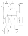
- the figure shows in the form of a block diagram a circuit arrangement according to the invention.
- the figure shows a schematic representation of an integrated circuit 1, which contains several circuit elements, and external circuit elements.
- a read-only memory 2 (ROM).
- Read / write memory 3 (RAM - Random Access Memory) is also provided.
- a circuit block 4 is also indicated, which may be circuit elements of a television set, not shown, in which the integrated circuit 1 and the memories 2 and 3 are inserted.
- a microprocessor 5 is provided within the integrated circuit 1, which controls all circuit elements provided in the integrated circuit 1.
- the integrated circuit 1 also has a display generator 6 which supplies a signal on the output side which can be displayed on a screen of the television set 4.
- a synchronization unit 7 is also provided in the integrated circuit, which supplies various clock signals for the circuitry within the integrated circuit 1.
- the synchronizing unit 7 is supplied with a clock signal of a fixed frequency, for example originating from a quartz oscillator.
- a memory unit 8 is also provided in the integrated circuit 1, which has a memory interface 9.
- a further memory interface 10 is provided which creates a connection for the circuit elements provided in the integrated circuit 1 to the externally provided read-only memory 2 and the externally provided read-write memory 3.
- a data reception unit 11 also provided in the integrated circuit 1 is coupled to circuit elements of the television set 4. The same applies to a control interface 12 of the integrated circuit 1.
- the integrated circuit 1 also has a data decoder 13.
- the microprocessor 5 assumes an essential function. because it controls almost all the elements shown.
- To control the Microprocessor 5 is a software program which is at least partially stored in the external read-only memory 2.
- This software program is advantageously divided into at least two levels. So-called operating system software is provided, which is based directly on the hardware of the microprocessor and, as such, does not yet enable complete functions. This relatively hardware-oriented operating system software is at least partially stored in the externally read-only read-only memory 2. If necessary, part of this software can also be stored in a memory provided in the integrated circuit 1 (not shown in FIG. 1).
- the advantages of the circuit arrangement according to the invention which consist in particular of a flexible adaptation, are not negatively affected by the provisional partial storage of this operating system software in the integrated circuit, since this operating system software is independent of the adaptation to different applications. It is hardware-oriented and therefore independent of changes in the desired functions.
- the application software which is based on this operating system software and which only provides the actual functions is completely stored in the externally provided read-only memory 2.
- This software can thus be easily adapted to changed conditions by replacing the memory 2.
- the memory interface 10 creates the connection to the external read-only memory 2 and the read-write memory 3. Via this, data is read from or written to the external memories.
- the microprocessor can configure memory areas in the external memories, in particular in the read-write memory 3, as required. The same applies to the memory unit 8 provided in the integrated circuit.
- Character sets required for the display of teletext or for the display of on-screen display functions are stored in the external read-only memory 2. These data can be read via the memory interface 10 and processed further in the integrated circuit 1, controlled by the microprocessor 5.
- the memory interface 10 for the external memories and the interface 9 of the memory unit 8 provided in the integrated circuit are connected directly via a DMA data exchange. In this way, a direct data exchange can take place between the storage units, which is only triggered by the microprocessor 5, but which does not have to be controlled in detail by it.
- the external read-only memory 2 can not only contain a universal character set, but also individual character sets depending on the user. These character sets can be read from the read-only memory 2 at any time. There is therefore no need to store or temporarily store such individual character sets in another case in the integrated circuit.
- Both the microprocessor 5 and the display generator 6 can access the memory unit provided in the integrated circuit 1 and the two external memories 2 and 3. This is done in a time sharing process.
- the data receiving unit 11 receives all picture lines of a television signal which is received by the television 4, for example. These data or image lines are converted analog to digital within the data receiving unit 11, the unit is synchronized to the converted data and the type of data is determined within the data receiving unit 11. The data are marked accordingly and stored in the internal storage unit 8.
- All picture lines are offered to the data receiving unit 11 by the externally provided television set 4.
- the data receiving unit 11 filters out the relevant ones.
- the data decoder 13 also provided in the integrated circuit 1 serves to decode coded data, if necessary. This can be, for example, Hamming decoding, CRC error correction or decryption of encrypted television programs.
- the data decoder 13 always runs, i.e. the data is always fed to it, regardless of whether it is encoded or uncoded data. This has the advantage that if it is recognized that it is encoded data, it does not have to be supplied to the data decoder 13 again for decoding. Otherwise, this would be necessary since at the point in time when it is recognized that it is encoded data, some of the data has already been transmitted. This data would then have to be fed to the decoder again. Due to the constant running of the decoder there is no need to read the data again and the decoded data is immediately available.
- the control interface 2 also provided in the integrated circuit 1 is a configurable interface to which the microprocessor 5 can assign different functions.
- SADC functions can be implemented in the control interface 12. This is software-controlled analog-digital conversion. These compare the analog input signal with a digital-to-analog converged analog signal. The result of this comparison is whether this is external supplied signal is larger or smaller than the comparison signal. This comparison signal is subsequently changed until it has largely approximated the externally supplied analog signal. The actual value of the analog signal is then determined.
- SADC functions can be used by means of the control interface 12, for example, for querying resistance matrices.
- Such a matrix consists of a network of resistors which are connected point by point, for example triggered by buttons to be actuated on the television set 4, to a reference potential. On the output side, the resistance matrix then supplies an analog signal that varies depending on the keys pressed. This signal can then be evaluated using such a SADC.
- 12 pulse width modulators can be implemented in the control interface, which deliver signals with pulses of varying width.
- Various control functions can be carried out in the television 4 by means of this.
- these can be controls for the audio functions, such as volume, tone control or the like.
- other control processes such as the tuner, can also be carried out.
- interrupts can also be evaluated by the control interface 12. Such interrupts can e.g. are triggered when control processes are to be marked. This can be, for example, key operations, but also other processes taking place in the television set 4. Such interrupts are generally used to detect non-synchronous events.
- control interface 12 so-called timer inputs are also provided, which are used to measure frequencies and pulse widths. Furthermore, so-called UARTS can be provided, which allow asynchronous serial data transmission both to the television 4 and from it to the integrated circuit 1.
- the display generator provided in the integrated circuit 1 can serve a variety of purposes. It can be provided, for example, for the display of teletext (teletext), but is also suitable for the display of so-called on-screen display displays in which, for example, parameters such as volume, tone control or the like set on the screen are displayed. Furthermore, the display generator 6 is suitable for generating or displaying graphics, including high-resolution graphics.
- the display generator 6 can, as is usual with teletext functions, work in a fixed matrix in line and column orientation. Certain characters must be used for different matrix positions. The data required for this are supplied by the data receiving unit 11. The characters as such are stored in the external read-only memory 2 or the read-write memory 3 and are read from the latter via the memory interface 10.
- the display generator 6 is designed to generate high-resolution graphics. This can be, for example, graphics that contain 12 x 10 pixels with two, four or 16 color values in one block.
- these graphic formats can also be changed or different graphic formats can be used for different display purposes, e.g. 6 x 10 x 4 per block.
- the display generator requires synchronized clock signals of different frequencies from the synchronization unit 7. The corresponding control is carried out by the microprocessor 5.
- Any kind of graphics can be generated in this way.
- the data of an output graphic are stored in the external read-only memory 2 and are read from it. This data can then be displayed. Furthermore, there is the possibility of further processing, ie changing, these data by means of the microprocessor 5.
- the resulting data of the intermediate steps can be in the external read-write memory 3 or in the internal Storage unit 8 can be stored. This can be done, for example, in such a way that the row-column information is stored in the internal memory unit and that the information about the individual pixels or pixels is stored in the external memory.
- additional fashion information can be stored in the external memory, which indicates how the stored pixel data are to be interpreted.
- This mode data specifies the format of the data, that is to say, for example, how much image data are provided for a pixel block in the horizontal or vertical direction and how much color information is provided for each pixel of this block.
- the line-column information is first of all generated from the internal memory unit 8 in order to display such a graphic read out. It is thus known which pixel data from the external memory 2 or 3 are required. These are read. Based on the fashion information, it is known which data are decisive for the color rendering. The corresponding bits are used by the display generator 6 to select the colors from a color palette.
- the display generator 6 has a digital-to-analog converter, which is not indicated in the illustration according to FIG. 1, by means of which the digital image data is initially used are converted into analog signals, which can be displayed, for example, on a screen of the television set 4.
- the pixel data can be provided with a so-called blending value, which indicates a value for cross-fading. This allows a mixing ratio to be defined with which the graphics and a video image are to be displayed.
- a so-called graphic cursor can be stored in the storage unit 8 or also in a further storage unit that may be provided. Such a graphic cursor can have various shapes, which can be selected individually depending on the intended use.
- This cursor data can be called up from the memory by the display generator 6 and can also be displayed.
- the microprocessor 5 can configure the display generator 6. Such a configuration can exist, for example, with regard to the display format (image-aspect ratio), number of lines or columns of the display, two-page display for teletext and the like.
- the microprocessor provided in the integrated circuit 1 performs all control tasks within the integrated circuit 1. It also serves to control any functions in the television 4 and accesses external memories 2 and 3 via the memory interface 10. In the microprocessor 5 all programs run that are required to control functions.
- the circuit arrangement according to the invention has the advantage that the external read-only memory 2 can easily be adapted to different operating conditions.
- the software programs contained in it, in particular the application-oriented software programs, can be changed at any time or the Read-only memory 2 can be replaced by another. Changes to these programs or also to the character sets likewise stored in the read-only memory 2 do not require any changes to the integrated circuit 1. This ensures a very flexible adaptation to different environmental conditions.
Landscapes
- Engineering & Computer Science (AREA)
- Multimedia (AREA)
- Signal Processing (AREA)
- Computer Graphics (AREA)
- Human Computer Interaction (AREA)
- Controls And Circuits For Display Device (AREA)
- Television Systems (AREA)
Applications Claiming Priority (2)
| Application Number | Priority Date | Filing Date | Title |
|---|---|---|---|
| DE19615086A DE19615086A1 (de) | 1996-04-17 | 1996-04-17 | Schaltungsanordnung für Anzeige- und Steuerungsfunktionen eines Fernsehgerätes |
| DE19615086 | 1996-04-17 |
Publications (2)
| Publication Number | Publication Date |
|---|---|
| EP0802674A2 true EP0802674A2 (fr) | 1997-10-22 |
| EP0802674A3 EP0802674A3 (fr) | 2000-12-06 |
Family
ID=7791481
Family Applications (1)
| Application Number | Title | Priority Date | Filing Date |
|---|---|---|---|
| EP97201013A Withdrawn EP0802674A3 (fr) | 1996-04-17 | 1997-04-07 | Agencement de circuit pour les fonctions d'affichage et de commande d'un appareil de télévision |
Country Status (4)
| Country | Link |
|---|---|
| US (1) | US6359655B1 (fr) |
| EP (1) | EP0802674A3 (fr) |
| JP (1) | JPH1042216A (fr) |
| DE (1) | DE19615086A1 (fr) |
Cited By (2)
| Publication number | Priority date | Publication date | Assignee | Title |
|---|---|---|---|---|
| CN1106111C (zh) * | 1998-11-27 | 2003-04-16 | 青岛海信电器股份有限公司 | 一种多媒体电视屏幕显示控制方法 |
| BE1014890A4 (fr) * | 1998-03-27 | 2004-06-01 | Funai Electric Co | Circuit de traitement video. |
Families Citing this family (4)
| Publication number | Priority date | Publication date | Assignee | Title |
|---|---|---|---|---|
| US20010034838A1 (en) * | 2000-01-14 | 2001-10-25 | Motoshi Ito | Control program, device including the control program, method for creating the control program, and method for operating the control program |
| DE10206554B4 (de) * | 2002-02-18 | 2005-07-14 | Micronas Munich Gmbh | Teletext-Anordnung mit einem programmierbaren externen Programmspeicher |
| US20050235087A1 (en) * | 2004-04-15 | 2005-10-20 | Stone Christopher J | Method, article of manufacture and apparatuses for establishing an isochronous signal for transmission to a signal receiving device |
| US11789071B2 (en) * | 2021-01-12 | 2023-10-17 | Texas Instruments Incorporated | High speed integrated circuit testing |
Family Cites Families (18)
| Publication number | Priority date | Publication date | Assignee | Title |
|---|---|---|---|---|
| IT1099331B (it) * | 1977-09-26 | 1985-09-18 | Philips Nv | Complesso ricevitore per televisione |
| US4342095A (en) * | 1979-04-02 | 1982-07-27 | Harris Corporation | Computer terminal |
| US4517598A (en) * | 1982-10-22 | 1985-05-14 | George Van Valkenburg | Method and apparatus for electronic publishing |
| US4633297A (en) * | 1985-04-01 | 1986-12-30 | Zenith Electronics Corporation | Television receiver having teletext processor with ROM for on-screen message |
| US5025374A (en) * | 1987-12-09 | 1991-06-18 | Arch Development Corp. | Portable system for choosing pre-operative patient test |
| GB2223650A (en) * | 1988-10-05 | 1990-04-11 | Philips Electronic Associated | Teletext decoder prevents over-writing of special character codes |
| NL8901724A (nl) * | 1989-07-06 | 1991-02-01 | Philips Nv | Teletext decoder en ontvanger van televisie signalen voor het ontvangen van cyclisch uitgezonden teletext pagina's. |
| US5371512A (en) | 1990-11-19 | 1994-12-06 | Nintendo Co., Ltd. | Background picture display apparatus and external storage used therefor |
| US5233423A (en) * | 1990-11-26 | 1993-08-03 | North American Philips Corporation | Embedded commericals within a television receiver using an integrated electronic billboard |
| GB9200426D0 (en) * | 1992-01-09 | 1992-02-26 | Philips Electronic Associated | Television receiver |
| ES2134822T3 (es) * | 1992-04-21 | 1999-10-16 | Koninkl Philips Electronics Nv | Decodificador de teletexto y receptor de television provisto de un decodificador de teletexto. |
| US5440632A (en) * | 1992-12-02 | 1995-08-08 | Scientific-Atlanta, Inc. | Reprogrammable subscriber terminal |
| US5621456A (en) * | 1993-06-22 | 1997-04-15 | Apple Computer, Inc. | Methods and apparatus for audio-visual interface for the display of multiple program categories |
| US5610665A (en) * | 1993-10-12 | 1997-03-11 | Berman; John L. | Interactive television graphics interface |
| EP0693854B1 (fr) * | 1994-07-18 | 2000-03-01 | Thomson Consumer Electronics, Inc. | Système de commande de la mise à jour des données du service de données étendues |
| US5529316A (en) * | 1995-02-16 | 1996-06-25 | American Axle & Manufacturing, Inc. | Adjustable tie rod assembly |
| US5703655A (en) * | 1995-03-24 | 1997-12-30 | U S West Technologies, Inc. | Video programming retrieval using extracted closed caption data which has been partitioned and stored to facilitate a search and retrieval process |
| JPH0993550A (ja) * | 1995-09-22 | 1997-04-04 | Toshiba Corp | 補完番組検知及び表示装置 |
-
1996
- 1996-04-17 DE DE19615086A patent/DE19615086A1/de not_active Withdrawn
-
1997
- 1997-04-07 EP EP97201013A patent/EP0802674A3/fr not_active Withdrawn
- 1997-04-07 US US08/838,489 patent/US6359655B1/en not_active Expired - Fee Related
- 1997-04-14 JP JP9095817A patent/JPH1042216A/ja active Pending
Cited By (3)
| Publication number | Priority date | Publication date | Assignee | Title |
|---|---|---|---|---|
| BE1014890A4 (fr) * | 1998-03-27 | 2004-06-01 | Funai Electric Co | Circuit de traitement video. |
| US6765627B2 (en) | 1998-03-27 | 2004-07-20 | Funai Electric Co., Ltd. | Video processing circuit for processing character signals |
| CN1106111C (zh) * | 1998-11-27 | 2003-04-16 | 青岛海信电器股份有限公司 | 一种多媒体电视屏幕显示控制方法 |
Also Published As
| Publication number | Publication date |
|---|---|
| EP0802674A3 (fr) | 2000-12-06 |
| JPH1042216A (ja) | 1998-02-13 |
| US6359655B1 (en) | 2002-03-19 |
| DE19615086A1 (de) | 1997-10-23 |
Similar Documents
| Publication | Publication Date | Title |
|---|---|---|
| DE2932525C2 (fr) | ||
| DE3310806C2 (fr) | ||
| DE69417476T3 (de) | Fernsehgerät fähig zum Vergrössern und Verkleinern des Bildes | |
| DE3852438T3 (de) | Anzeigevorrichtung zur gleichzeitigen Darstellung eines Fernsehbildes und einer komprimierten Anzeigeseite mit Zeichendaten und grafischen Daten. | |
| DE4332573C2 (de) | Videographiksystem zum Anzeigen von Signalverläufen auf einem Videomonitor | |
| DE69015536T2 (de) | Fensterdehnung für Farbfernsehen und Korrektur der Überabtastung für hochauflösende Rastergraphikanzeigen. | |
| DE69525862T2 (de) | Anzeigegerät mit wählbarem kommunikationsprotokoll | |
| DE2740009A1 (de) | Vorrichtung zur steuerung von information, die auf einer fernsehartigen sichtvorrichtung dargestellt werden soll | |
| DE3228354A1 (de) | Benutzerfuehrende bedienung bei geraeten der unterhaltungselektronik | |
| DE2735213B2 (de) | Gerät zum Steuern der Bilddarstellung bei einem Farbfernsehgerät | |
| DE4240011A1 (de) | Bildschirmanzeigevorrichtung für einen Multimoden-Monitor und zugehöriges Verfahren | |
| DE2935746A1 (de) | Farbgenerator fuer eine einrichtung zur digitalen steuerung einer raster-abtast-bildwiedergabe | |
| EP1855469B1 (fr) | Appareil électronique comportant un actionneur pour entrer des paramètres opérationnels | |
| DE69320998T2 (de) | Fernsehempfänger | |
| DE69509482T2 (de) | Verfahren zur übertragung von videotextseiten | |
| EP0802674A2 (fr) | Agencement de circuit pour les fonctions d'affichage et de commande d'un appareil de télévision | |
| EP0483463B1 (fr) | Dispositif de programmation des chaînes pour une réception par satellite | |
| DE2724094B2 (de) | Kathodenstrahl-Anzeigevorrichtung | |
| DE3914697A1 (de) | Verfahren zum uebertragen von teletextdaten | |
| DE2855731A1 (de) | Einrichtung zur farbwiedergabe unter verwendung eines hilfsspeichers fuer farbinformationen | |
| DE2439102A1 (de) | Verfahren zum darstellen von bildern in form von digitalen daten | |
| DE19653071A1 (de) | Verfahren zur Ersetzung von Teilen eines digitalkodierten Bildes sowie Vorrichtung zur Durchführung des Verfahrens | |
| EP0770307B1 (fr) | Appareil de traitement de signaux video pourvu d'un dispositif de traitement de teletexte | |
| DE69015862T2 (de) | Zeichengenerator zur Wiedergabe von Zeichen mit einem Schatten auf einem Bildschirm. | |
| EP0561028B1 (fr) | Procédé pour l'affichage des pages de texte sur l'écran d'un poste de télévision |
Legal Events
| Date | Code | Title | Description |
|---|---|---|---|
| PUAI | Public reference made under article 153(3) epc to a published international application that has entered the european phase |
Free format text: ORIGINAL CODE: 0009012 |
|
| AK | Designated contracting states |
Kind code of ref document: A2 Designated state(s): DE FR GB IT |
|
| RAP3 | Party data changed (applicant data changed or rights of an application transferred) |
Owner name: KONINKLIJKE PHILIPS ELECTRONICS N.V. Owner name: PHILIPS CORPORATE INTELLECTUAL PROPERTY GMBH |
|
| PUAL | Search report despatched |
Free format text: ORIGINAL CODE: 0009013 |
|
| AK | Designated contracting states |
Kind code of ref document: A3 Designated state(s): DE FR GB IT |
|
| 17P | Request for examination filed |
Effective date: 20010606 |
|
| RAP1 | Party data changed (applicant data changed or rights of an application transferred) |
Owner name: KONINKLIJKE PHILIPS ELECTRONICS N.V. Owner name: PHILIPS CORPORATE INTELLECTUAL PROPERTY GMBH |
|
| RAP1 | Party data changed (applicant data changed or rights of an application transferred) |
Owner name: KONINKLIJKE PHILIPS ELECTRONICS N.V. Owner name: PHILIPS INTELLECTUAL PROPERTY & STANDARDS GMBH |
|
| 17Q | First examination report despatched |
Effective date: 20061031 |
|
| RAP1 | Party data changed (applicant data changed or rights of an application transferred) |
Owner name: NXP B.V. |
|
| STAA | Information on the status of an ep patent application or granted ep patent |
Free format text: STATUS: THE APPLICATION IS DEEMED TO BE WITHDRAWN |
|
| 18D | Application deemed to be withdrawn |
Effective date: 20070313 |