EP0802681B1 - Décodeur pour code à longueur variable - Google Patents
Décodeur pour code à longueur variable Download PDFInfo
- Publication number
- EP0802681B1 EP0802681B1 EP19970301685 EP97301685A EP0802681B1 EP 0802681 B1 EP0802681 B1 EP 0802681B1 EP 19970301685 EP19970301685 EP 19970301685 EP 97301685 A EP97301685 A EP 97301685A EP 0802681 B1 EP0802681 B1 EP 0802681B1
- Authority
- EP
- European Patent Office
- Prior art keywords
- latch
- signal
- code word
- code
- multiplexer
- Prior art date
- Legal status (The legal status is an assumption and is not a legal conclusion. Google has not performed a legal analysis and makes no representation as to the accuracy of the status listed.)
- Expired - Lifetime
Links
- 230000004044 response Effects 0.000 claims description 64
- 239000000872 buffer Substances 0.000 claims description 55
- 238000003860 storage Methods 0.000 claims description 49
- 238000004519 manufacturing process Methods 0.000 claims description 26
- 230000006870 function Effects 0.000 description 16
- 238000010586 diagram Methods 0.000 description 9
- 238000000034 method Methods 0.000 description 3
- 230000005540 biological transmission Effects 0.000 description 2
- 230000006386 memory function Effects 0.000 description 2
- 238000012986 modification Methods 0.000 description 2
- 230000004048 modification Effects 0.000 description 2
- 230000006835 compression Effects 0.000 description 1
- 238000007906 compression Methods 0.000 description 1
- 230000001419 dependent effect Effects 0.000 description 1
- 230000009467 reduction Effects 0.000 description 1
- 238000004904 shortening Methods 0.000 description 1
- 230000001131 transforming effect Effects 0.000 description 1
Images


Classifications
-
- H—ELECTRICITY
- H03—ELECTRONIC CIRCUITRY
- H03M—CODING; DECODING; CODE CONVERSION IN GENERAL
- H03M7/00—Conversion of a code where information is represented by a given sequence or number of digits to a code where the same, similar or subset of information is represented by a different sequence or number of digits
- H03M7/30—Compression; Expansion; Suppression of unnecessary data, e.g. redundancy reduction
- H03M7/40—Conversion to or from variable length codes, e.g. Shannon-Fano code, Huffman code, Morse code
- H03M7/42—Conversion to or from variable length codes, e.g. Shannon-Fano code, Huffman code, Morse code using table look-up for the coding or decoding process, e.g. using read-only memory
- H03M7/425—Conversion to or from variable length codes, e.g. Shannon-Fano code, Huffman code, Morse code using table look-up for the coding or decoding process, e.g. using read-only memory for the decoding process only
-
- H—ELECTRICITY
- H03—ELECTRONIC CIRCUITRY
- H03M—CODING; DECODING; CODE CONVERSION IN GENERAL
- H03M7/00—Conversion of a code where information is represented by a given sequence or number of digits to a code where the same, similar or subset of information is represented by a different sequence or number of digits
- H03M7/30—Compression; Expansion; Suppression of unnecessary data, e.g. redundancy reduction
- H03M7/40—Conversion to or from variable length codes, e.g. Shannon-Fano code, Huffman code, Morse code
-
- H—ELECTRICITY
- H04—ELECTRIC COMMUNICATION TECHNIQUE
- H04N—PICTORIAL COMMUNICATION, e.g. TELEVISION
- H04N19/00—Methods or arrangements for coding, decoding, compressing or decompressing digital video signals
- H04N19/60—Methods or arrangements for coding, decoding, compressing or decompressing digital video signals using transform coding
-
- H—ELECTRICITY
- H04—ELECTRIC COMMUNICATION TECHNIQUE
- H04N—PICTORIAL COMMUNICATION, e.g. TELEVISION
- H04N19/00—Methods or arrangements for coding, decoding, compressing or decompressing digital video signals
- H04N19/10—Methods or arrangements for coding, decoding, compressing or decompressing digital video signals using adaptive coding
- H04N19/102—Methods or arrangements for coding, decoding, compressing or decompressing digital video signals using adaptive coding characterised by the element, parameter or selection affected or controlled by the adaptive coding
- H04N19/13—Adaptive entropy coding, e.g. adaptive variable length coding [AVLC] or context adaptive binary arithmetic coding [CABAC]
-
- H—ELECTRICITY
- H04—ELECTRIC COMMUNICATION TECHNIQUE
- H04N—PICTORIAL COMMUNICATION, e.g. TELEVISION
- H04N19/00—Methods or arrangements for coding, decoding, compressing or decompressing digital video signals
- H04N19/90—Methods or arrangements for coding, decoding, compressing or decompressing digital video signals using coding techniques not provided for in groups H04N19/10-H04N19/85, e.g. fractals
- H04N19/91—Entropy coding, e.g. variable length coding [VLC] or arithmetic coding
Definitions
- the present invention relates to a VLC(Variable Length Code) decoder.
- the VLC (Variable Length Code), sometimes called as the Hoffmann code, is an optimal code used in a high speed transmission system, to which statistical characteristics of a data is applied, in a manner that once the statistical characteristics of a data are known, the shorter code word is designated, the more frequent video data are generated, and the longer code word is designated, the less frequent video data are generated. If appropriate code words are designated to all possible video data by such a method, an average bit length of code words can be compressed shorter than an originally intended average bit length. Therefore, this VLC is a lossless coding method frequently used for a data of which statistical characteristics are well known.
- This VLC is actually employed in systems which require a technique for compressing a video data, such as MPEG 1(Moving Picture Expert Group 1), MPEG 2(Moving Picture Expert Group 2) and HDTV(High Definition Television) for denser compression of the data.
- MPEG 1 Motion Picture Expert Group 1
- MPEG 2 Motion Picture Expert Group 2
- HDTV High Definition Television
- a speed of this function block is dependent on the longest delay time existing in parts connecting the variable length code decoder and the circuits around it. Therefore, in providing a variable length code decoder which will form one function block connected with circuits around it in a system, such as MPEG 1, MPEG 2, or HDTV, not only the longest delay time of the variable length code decoder itself, but also the longest delay time existing in parts connecting the variable length code decoder and the circuits around it, should be taken into account.
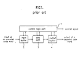
- an encoded code word(or a data) received at an input buffer 2 is decoded by a data path 3 having a variable length code decoder included therein under the control of a control logic part 1, and produced through an output buffer 4.
- variable length code decoder in general forms a function block, together with circuits around it connected thereto.
- an output of the VLC table may be directly stored in an input buffer in other function block, in most cases, the output is applied to one or more circuits around it, or stored in the input buffer of other function block after being converted into other suitable form in other function block.
- FIG. 2 illustrates a block diagram showing a prior art variable length code decoder.
- the prior art variable length code decoder includes an input buffer 201, a first latch part 202, a first barrel shifter 203, a second latch part 204, a second barrel shifter 205, a VLC table 206, a first latch 207, a control signal generating part 208 and an output buffer 209.
- the first latch part 202 includes a second latch 202a and a third latch 202b
- the second latch part 204 includes a fourth latch 204a and a fifth latch 204b.
- the control signal generating part includes an adder 208a and a sixth latch 208b.
- the VLC table 206 having random logic decodes successive code words continuously to produce decoded code words of a fixed length in response to a read signal of a fixed symbol clock rate.
- the first latch part 202 and the barrel shifter 203 appropriately interfaces between the input buffer 201 and the second latch part 204.
- the input buffer 201 stores a serial bit stream of code words having variable lengths received from a data channel into a data segment having a fixed length.
- the control signal generating part 208 produces 16 bit sized data in parallel in response to the read signal from the sixth latch 208b.
- the VLC table 206 produces a bit length of a code word of an unknown bit length and a decoded code word having the bit length to apply to the latch 207 and the output buffer 209, respectively.
- the output side of the second barrel shifter 205 provides a decoding window to the VLC table 206 and is controlled by a bit lengths of the decoded code words accumulated in the first latch 207 up to a prior clock of the present clock.
- Code words of variable lengths are provided from the latches 204a and 204b to the second barrel shifter 205.
- Each of the latches 204a and 204b has a bit capacity at least the same with the code word of the longest length.
- the second latch part 204 provides successive bits having at least two variable length code words.
- An output side of the second barrel shifter 205 is connected to an input side of the VLC table 206, to apply bits of the longest code word to be decoded of the successive bits of a length two times of the longest code word stored in the fourth latch 204a and the fifth latch 204b during input data are provided from the fifth latch 204b to the first latch part 202 and the first barrel shifter 203.
- the VLC table 206 applies the length of the code word received from the second barrel shifter 205 to the first latch 207, and the decoded code word to the output buffer 209.
- the second barrel shifter 205 is controlled by the lengths of the code words decoded up to a prior clock received from the first latch 207.
- an output window of the second barrel shifter 205 is shifted by the bit lengths of the code words decoded up to a prior clock received from the first latch 207, to starts from the first bit of a code word to be decoded, newly Since all the bits in the fourth latch 202a are transformed at all clocks, the fifth latch 204b is filled again with a corresponding bit stream from the first barrel shifter 203 which has an interfacing function during a cycle corresponding to each clock. That is, a successive bit stream starting from the first bit of a decoded code word appears on the input side of the second barrel shifter 205.
- the first barrel shifter 203 provides a bit stream to the fifth latch 204b, this bit stream is not included in the longest delay time because this bit stream is applied to the fifth latch 204b, directly.
- the bit stream of code words decoded at a prior clock appeared on the input side of the second barrel shifter 205 should be up-dated during a cycle corresponding to each clock without fail.
- an input to the fifth latch 204b is provided from the interfacing first barrel shifter 203.
- a code word is provided to an input side of the interfacing first barrel shifter 203 from the two successive latches 202a and 202b having a capacity for the longest code word length and the input buffer 201.
- the interfacing second, and third latches 202a and 202b have a bit capacity for the longest code word length which may be produced by the input buffer 201.
- the output of the first barrel shifter 203 is controlled both by the length of the code word decoded from the output of the VLC table 206 and the output of the adder 208a which adds up the lengths of the code words decoded up to a prior clock of the present clock received from the sixth latch 208b in the control signal generating part 208.
- the output of the first barrel shifter 203 is shifted according to bit lengths of the decoded code words added up by the adder 208a, to produce outputs of the second barrel shifter 205 and the successive bit streams.
- a series of bit sequence from the interfacing first barrel shifter 203 appears on the input side of the second barrel shifter 205.
- a carry is generated. This means that all the bits at storage in the interfacing first latch 202a have been transferred to the fifth latch 202a through the first barrel shifter 203. Because of this carry, all the bits in the third latch 202b are transferred to the second latch 202a, and the code words from the input buffer 201 are transferred to the interfacing second latch 202a. And, on the same time, new 16 bit size data are provided to the third latch 202b and the first barrel shifter 203 from the input buffer 201.
- variable length code decoder when implementing a high quality picture system, such as MPEG 1, MPEG 2, or HDTV, the variable length code decoder forms a function block, together with circuits around it connected thereto in many cases. And, though the outputs from the VLC table and decoded code bits may be directly stored in input buffers in function blocks different from each other, they are applied to circuits around the VLC table as input data or used as control signals for other function blocks in most cases. Therefore, it is necessary to decode bits of the code words in the shortest time while preventing the trouble from the longest delay time.
- Document EP0681404 discloses in Figures 2A,2B a variable length code decoder similar to the one disclosed by document US5245338, where in Figure 2B multiplexers 16 and 17 are further inserted between the output of the three latches 13,14,15 and the 1st barrel shifter 18.
- Embodiments of the present invention are directed to a variable length code decoder that substantially obviates one or more of the problems due to limitations and disadvantages of the related art.
- variable length decoder which can shorten the longest delay time existing in parts connecting a VLC decoder and circuits around it and reduce a chip area of an integrated circuit of a function block in fabrication.
- variable length code decoder including the features which form the subject-matter of claim 1 in the attached claims.
- Fig. 3 illustrates a block diagram showing a variable length code decoder in accordance with a first embodiment of the present invention.
- the variable length code decoder in accordance with a first embodiment of the present invention includes an input buffer 310 for storing code words applied thereto in series in parallel by 16 bits and producing the code words in response to a read signal, a latch part 320 for temporary storage and production of the code words received in response to the read signal, a multiplexing part 330 for receiving the code words from the latch part 320 and selectively producing the code words in response to a multiplexing signal, a barrel shifter 340 for shifting an output window thereof in response to a shift signal and producing a predetermined number of bits of the code words from the multiplexing part 330 for decoding, a latch 350 for temporary storage and production of the code words from the barrel shifter 340, a PLA(Programmable Logic Array) 360 as a VLC table for producing a decoded code word and a bit length of the code word from the latch 350, and a control signal generating part 370 for adding the bit lengths of the decoded code words up to a clock
- the latch part 320 includes a first latch 321 for temporary storage and production of the code words from the input buffer 310 in response to the read signal, a second latch 322 for temporary storage and production of the code words from the first latch 321 in response to the read signal, and a third latch 323 for temporary storage and production of the code words from the second latch 322 in response to the read signal.
- the multiplexing part 330 includes a first multiplexer 331 for selecting one of the code words from the input buffer 310 and the first, and second latches 321 and 322 in the latch part 320 in response to the multiplexing signal and producing the selected code word as backward 16 bits of the barrel shifter 340, and a second multiplexer 332 for selecting one of the code words from the first, second, and third latches 321, 322 and 323 in the latch part 320 in response to the multiplexing signal and producing the selected code word as forward 16 bits of the barrel shifter 340.
- the multiplexing part 330 acts as a switching part. Therefore, the multiplexing part 330 may be replaced with another device that can act as a switching part.
- the latch 350 is called as a fourth latch, hereafter.
- the control signal generating part 370 includes a third multiplexer 371 for receiving, selecting and producing an initial setting signal and selecting a bit length of a code word decoded at the present clock received from the PLA 360, a fifth latch 372 in storage of a sum of the bit lengths of the code words decoded up to a clock just prior to the present clock, an adder 373 for adding the bit length from the third multiplexer 371 and an output data from the fifth latch 372 to produce the shift signal and a carry signal for shifting the output window of the barrel shifter 340, a sixth latch 374 for temporary storage of the carry signal received from the adder 373 and producing the stored carry signal as the read signal at the next clock, and a multiplexing controlling part 375 for using the carry signal received from the adder 373 and the read signal received from the sixth latch 324 in producing the multiplexing signal for making the multiplexing part 330 to select one of input terminals thereof.
- the PLA 360 being a VLC table, is a kind of memory. Accordingly, the PLA 360 can produce a decoded code word and a bit length of a received code word. Therefore, the PLA may be replaced with another device which can act as a memory.
- Fig. 4 illustrates a structure of a bit stream applied to the input buffer shown in Fig. 3
- Fig. 5 is a table for explaining operation of the variable length code decoder shown in Fig. 3 at each clock.
- Code words of variable lengths applied to the input buffer 310 from outside of the input buffer 310 are produced from the input buffer 310 by 16 bits according to a fixed symbol clock rate.
- the longest bit length of the code words of variable lengths is 16 bits.
- each of the first, second, and third latches 321, 322 and 323 in the latch part 320 being bit register, has a capacity for the longest code word.
- An input to the barrel shifter 340 of 32 bits is provided from the first, and second multiplexers 331 and 332 in the multiplexing part 330, and a 16 bit sliding decoding window is provided as the output window of the barrel shifter 340 of which shift is controlled by the shift signal from the control signal generating part 370.
- the first multiplexer 331 and the second multiplexer 332 provide backward 16 bits and forward 16 bits to the barrel shifter 340, respectively.
- the renewed 16 bit code word from the barrel shift 340 is applied to the PLA 360, which is a kind of memory, through the fourth latch 350.
- the PLA 360 includes a code word table, a decoded code word table and a code word length table.
- the code word table in the PLA 360 detects bit patterns of code words stored therein for a code word corresponding to a bit pattern identical to the order of bits of a received code word.
- the decoded code word table in the PLA 360 produces code words of a fixed length corresponding to the code words of variable lengths detected in the code word table, that is, decoded code words.
- the code word length table produces bit lengths of the code words of variable lengths detected in the code word table.
- the code word length from the code word length table in the PLA 360 is added to the bit lengths of the code words decoded up to a right before clock in the adder 373, and this accumulated signal is used as a shifting signal for shifting the output window of the barrel shifter 340.
- This adder also generates a carry signal, of "1" if the sum of the accumulated code words is longer than the longest bit length of the code word, and, of "0" if shorter, and provides to the sixth latch 374.
- the multiplexing controlling part 375 provides a multiplexing signal to the first multiplexer 331 and the second multiplexer 332 so that the first multiplexer 331 and the second multiplexer 332 selectively produce the output signal from the second latch 322 and the output signal from the third latch 323 respectively, if the carry signal and the read signal are 1(high) and 0(low), or 0 and 1 respectively, the multiplexing controlling part 375 provides a multiplexing signal to the first multiplexer 331 and the second multiplexer 332 so that the first multiplexer 331 and the second multiplexer 332 selectively produce the output signal from the first latch 321 and the output signal from the second latch 322 respectively, and if the carry signal and the read signal are 1(high) and 1(high) respectively, the multiplexing controlling part 375 provides a multiplexing signal to the first multiplexer 331 and the second multiplex
- a code word having the data stream of Fig. 4 is applied to the input buffer shown in Fig. 3.
- arbitrary 16 bits are forcibly applied to the third multiplexer 371 in the control signal generating part 370 as an initial setting signal to make all the carry signal and the read signal "high".
- the input buffer 310 produces 16 bits a 1 -a 8 b 1 -b 6 c 1 -c 2 including the first bit of the received code word.
- the "1" herein means high, and "0" means low.
- the second multiplexer 332 selects a code word from the first latch 321, and the first multiplexer 331 selects a code word from the input buffer 310. That is, the first multiplexer 331 selects and produces an output signal a 1 -a 8 b 1 -b 6 c 1 -c 2 and the barrel shifter 340, which receives 32 bits, shifts its output window, a sliding decoding window, by 16 bits. In this case, no signal is produced from the barrel shifter 340.
- arbitrary 16 bits are forcibly applied to the third multiplexer 371 in the control signal generating part 370 as an initial setting signal to the carry signal "1", and make the read signal "1" by the carry signal generated in the adder 373 at the first clock, resulting the input buffer 310 to produce a code word c 3 -c 5 d 1 -d 13 .
- the data a 1 -a 8 b 1 -b 6 c 1 -c 2 produced from the input buffer 310 at the first clock is stored in the second latch 322 by the read signal, and, since all the carry signal and the read signal are 1 and 1, the second multiplexer 332 selectively produces a signal a 1 -a 8 c 1 -b 6 c 1 c 2 from the first latch 321 in response to the multiplexing signal from the multiplexing controlling part 375 and the first multiplexer 331 selectively produces a signal c 3 -c 5 d 1 -d 13 .
- the barrel shifter 340 received the signals from the first latch 321 and the input buffer 310, shifts its sliding decoding window by 16 bits from the present state transfers the code word a 1 -a 8 b 1 -b 6 c 1 -c 2 from the first latch 321 to the fourth latch 350
- the read signal becomes "l” by the carry signal at the previous second clock, the carry signal becomes "0" because the signal a 1 -a 8 to be decoded actually is of 8 bits, and the input buffer 310 produces the next signal bit stream d 14 d 15 e 1 -e 12 f 1 f 2 .
- the first latch 321 in the latch part 320 stores a data c 3 -c 5 d 1 -d 13 from the input buffer 310 at the previous second clock
- the second latch 322 stores a data a 1 -a 8 b 1 -b 6 c 1 -c 2 from the first latch 321 at the previous second clock
- the fourth latch 350 stores a data a 1 -a 8 b 1 -b 6 c 1 -c 2 from the barrel shifter 340 at the previous second clock.
- the second multiplexer 332 and the first multiplexer 331 select the data a 1 -a 8 b 1 -b 6 c 1 -c 2 from the second latch 322 and the data c 3 -c 5 d 1 -d 13 from the first latch 321 respectively and apply to the input side of the barrel shifter 340.
- the barrel shifter 340 Upon reception of a signal(or a data) from the first, and second multiplexers 331 and 332, the barrel shifter 340 shifts its sliding decoding window as much as the length a 1 -a 8 (8 bits) of the code word decoded at the previous second clock and produces a data b 1 -b 6 c 1 -c 5 d 1 -d 5 in response to the shift signal from the control signal generating part 370.
- the aforementioned steps are repeated continuously during the variable length code decoder is in operation.
- variable length code decoder in accordance with a second embodiment of the present invention will be explained, hereinafter.
- a multiplexing part which has a switching function, is also used in the second embodiment in place of the second barrel shifter used in the prior art.
- Fig. 6 illustrates a block diagram showing the variable length code decoder in accordance with the second embodiment of the present invention.
- variable length code decoder in accordance with the second embodiment of the present invention includes an input buffer 610 for making a code word applied thereto in series into parallel code words of 16 bits and producing the parallel code words in response to a read signal, a latch part 620 for temporary storage and production of the code words received from the input buffer 610 in response to the read signal, a multiplexing part 630 for selecting and producing the code words from the latch part 620 and the code words from the input buffer 610 in response to a multiplexing signal, a barrel shifter 640 for shining a sliding output decoding window by lengths of code words decoded up to a prior clock signal in response to a shift signal and producing a predetermined number of bits(in this case 16 bits) of the code words from the multiplexing part 630, a PLA(Programmable Logic Array) 650 for producing a decoded code word and a bit length of the decoded code word corresponding to the code word from the barrel shifter 640, and a control signal
- the latch part 620 includes a first latch 621 for temporary storage and production of the code words from the input buffer 610 in response to the read signal, and a second latch 622 for temporary storage and production of the code words from the first latch 621 in response to the read signal.
- the multiplexing part 630 includes a first multiplexer 631 for selecting one of the code words from the input buffer 610 and the first latch 621 in the latch part 620 in response to the multiplexing signal and producing the selected code word as backward 16 bits of the barrel shifter 640, and a second multiplexer 632 for selecting one of the code words from the first, and second latches 621 and 622 in the latch part 620 in response to the multiplexing signal and producing the selected code word as forward 16 bits of the barrel shifter 640
- the control signal generating part 660 includes a third multiplexer 661 for receiving and producing an initial setting signal and selecting a bit length of a code word decoded at the present clock received from the PLA 650, a third latch 662 in storage of a sum of the bit lengths of the code words decoded up to a clock just prior to the present clock, an adder 663 for adding the bit length of a code word decoded at the present time received from the third multiplexer 661 and bit lengths of code words decoded up to a clock just prior to the present clock received from the third latch 662 to produce the shift signal and a carry signal, a fourth latch 664 for temporary storage of the carry signal received from the adder 663 and producing the stored carry signal as the read signal at a clock next to the present clock, and a multiplexing controlling part 665 for using the carry signal received from the fourth latch 664 in producing the multiplexing signal for selecting one of input terminals on the multiplexing part 630.
- the shift signal is a signal for shifting the decoding output window of the barrel shifter 640 by a predetermined number of bits
- the carry signal is a signal of "1" or "0" generated when the output of the adder 663 is greater or smaller than the longest bit length.
- variable length code decoder in accordance with the second embodiment of the present invention will be explained.
- the input buffer 610 Upon reception of code words of variable lengths in series, the input buffer 610 produces the code words to the first latch 621 by 16 bits in parallel at a constant symbol rate in response to a read signal.
- the 32 bits is applied to the barrel shifter 640 by the first, and second multiplexers 631 and 632 in the multiplexing part 630.
- the output window on the barrel shifter 640 is a sliding decoding window for 16 bits.
- the multiplexing controlling part 665 selects on of the two input terminals of the first, and second multiplexers 631 and 632.
- the "0" and “1" represent a low value and a high value, respectively.
- the first multiplexer 631 and the second multiplexer 632 produce a code word from the input buffer 610 and a code word from the first latch 621 respectively in response to a multiplexing signal from the multiplexing controlling part 665 if the read signal is "1", and produce a code word from the first latch 621 and a code word from the second latch 622 respectively if the read signal is "0".
- the renewed 16 bits from the barrel shifter 640 are connected to the PLA 650, which is a VLC table.
- the PLA 650 being a kind of memory, can be replaced with another device which has a memory function.
- the system and operation of the PLA 650 are the same with the PLA 360 shown in Fig. 3. That is, the PLA 650 produces a decoded code word corresponding to the 16 bits received from the barrel shifter 640 and produces a length of the decoded code word to the third multiplexer 661 in the control signal generating part 660.
- the adder 663 produces "0" if the added value is smaller than a bit length value of a preset longest code word, and produces "1” if the added value is greater than a bit length value of the preset longest code word.
- the second embodiment variable length code decoder is a model suitable for a case when a fast speed in not required within a variable length code decoder. As shown in Fig. 6, the latch 350 which is included in Fig. 3 is excluded to suit to systems which do not require a fast speed in the decoder.
- Fig. 7 illustrates a block diagram showing a variable length code decoder in accordance with a third embodiment of the present invention.
- variable length code decoder in accordance with the third embodiment of the present invention includes an input buffer 710 for transforming a code word applied thereto in series into parallel code words of 16 bits and producing the parallel code words in response to a read signal, a latch part 720 for temporary storage and production of the code words received from the input buffer 710 in response to the read signal, a multiplexing part 730 for selecting and producing the code words from the latch part 720 in response to a multiplexing signal, a barrel shifter 740 for shifting a sliding decoding window(or an output window) in response to a shift signal and producing a predetermined number of bits of the code word from the multiplexing part 730, a latch 750 for temporary storage and production of the code word from the barrel shifter 740, a PLA(Programmable Logic Array) 760 for producing a decoded code word and a bit length of the decoded code word corresponding to the code word from the latch 750, a control signal generating part 760 for adding
- the latch part 720 includes a first latch 721 for temporary storage and production of the code words from the input buffer 710 in response to the read signal, and a second latch 722 for temporary storage and production of the code words from the first latch 721 in response to the read signal.
- the multiplexing part 730 includes a first multiplexer 731 for selecting one of the code words from the input buffer 710 and the first latch 721 in the latch part 720 in response to the multiplexing signal and producing the selected code word as backward 16 bits of the barrel shifter 740, and a second multiplexer 732 for selecting one of the code words from the first, and second latches 721 and 722 in the latch part 720 in response to the multiplexing signal and producing the selected code word as forward 16 bits of the barrel shifter 740.
- the latch 750 is called as a third latch.
- the control signal generating part 770 includes a third multiplexer 771 for receiving and producing an initial setting signal and receiving and producing a bit length of a code word decoded at the present clock in the PLA 760, a fourth latch 772 in storage of a sum of the bit lengths of the code words decoded up to a clock just prior to the present clock, an adder 773 for adding the code word received from the third multiplexer 771 and the code words received from the fourth latch 772 to produce the shift signal for shifting the output window(or the sliding decoding window) of the barrel shifter 740 and producing "0" if the added value is greater than a preset longest bit length of a code word and "1" if the added value is smaller than the preset longest bit length of a code word, and a multiplexing controlling part 775 for using the read signal received from the adder 773 in producing the multiplexing signal for selecting one of inputs from the first, and second multiplexers 731 and 732.
- the third embodiment variable length code decoder having the aforementioned system is used when circuits around the decoder connected with output sides of the decoder for applying the read signal are not complicated.
- variable length code decoder in accordance with the third embodiment of the present invention will be explained.
- the input buffer 710 produces variable length code words received in series in parallel by 16 bits at a constant symbol rate in response to a read signal.
- the 32 bits from the first, and second multiplexers 731 and 732 in the multiplexing part 730 are applied to an input side of the barrel shifter 740.
- the output window on the barrel shifter 740 is a sliding decoding window for 16 bits.
- the first multiplexer 731 and the second multiplexer 732 When the read signal is "1", the first multiplexer 731 and the second multiplexer 732 produce the code word from the input buffer 710 and the code word from the first latch 721 in response to the multiplexing signal provided from the multiplexing controlling part 774 respectively, and when the read signal is "0", the first multiplexer 731 and the second multiplexer 732 produce the code word from the first latch 721 and the code word from the second latch 722 in response to the multiplexing signal provided from the multiplexing controlling part 774, respectively.
- the output side of the barrel shifter 740 is connected to the third latch 750, and the output side of the third latch 750 is connected with the PLA 760, which is a VLC table. Since the PLA 760 is a kind of memory, the PLA 760 may be replaced with another device which has a memory function.
- the PLA 760 produces a decoded code word and a bit length of the decoded code word corresponding to a received code word.
- the bit length of the code word decoded at the present clock received from the PLA 760 and values of the bits of the code words decoded up to a clock just prior to the present clock stored in the fourth latch 772 are added in the adder 773, and directly used for shifting the sliding decoding output window on the barrel shifter 740.
- the multiplexing controlling part 774 provides the multiplexing signal for selecting one from the two input terminals of the first multiplexer 731 and the second multiplexer 732.
- variable length code decoder embodying the invention has the following advantages over the decoder of the prior art.
- the use of the multiplexers instead of the barrel shifter can reduce the area of an integrated circuit on the same delay time basis.
- the shortening of the delay time existing between a variable length code decoder and circuits around it facilitates to implement a function block of faster operation speed.
- variable length code decoder described without departing from the scope of the invention.
- present invention cover the modifications and variations of this invention provided they come within the scope of the appended claims and their equivalents.
Landscapes
- Engineering & Computer Science (AREA)
- Theoretical Computer Science (AREA)
- Multimedia (AREA)
- Signal Processing (AREA)
- Compression, Expansion, Code Conversion, And Decoders (AREA)
- Compression Or Coding Systems Of Tv Signals (AREA)
Claims (22)
- Décodeur pour code à longueur variable comprenant:une première partie de stockage destinée au stockage provisoire et à la production d'un mot de code reçu en réponse à un signal lu;une partie de commutation destinée à la production sélective des mots de code à partir de la première partie de stockage et du mot de code reçu au niveau de la première partie de stockage en réponse à un signal de commutation;un décaleur à barillet destiné à décaler une fenêtre de sortie de décodage sur celui-ci en réponse à un signal de décalage en produisant un nombre prédéterminé de bits du mot de code provenant de la partie de commutation pour décodage;une table destinée à produire un mot de code décodé et une longueur binaire du mot de code décodé du nombre prédéterminé de bits produit à partir du décaleur à barillet ; etune partie de génération de signal de commande destinée à utiliser la longueur binaire d'un mot de code à l'horloge actuelle reçu à partir de la table pour la génération du signal de commutation, du signal de décalage et du signal lu.
- Décodeur pour code à longueur variable selon la revendication 1, comprenant en outre:une seconde partie de stockage destinée au stockage provisoire et à la production du mot de code provenant du décaleur à barillet, la table produisant le mot de code décodé et la longueur binaire à partir du nombre prédéterminé de bits stockés dans la seconde partie de stockage.
- Décodeur pour code à longueur variable selon la revendication 1 ou 2, dans lequel la partie de commutation comprend au moins un multiplexeur.
- Décodeur pour code à longueur variable selon la revendication 1 ou 2, comprenant en outre:un tampon d'entrée destiné à recevoir un mot de code en série et à appliquer le mot de code en unités parallèles d'un nombre de bits prédéterminé à la première partie de stockage; etun tampon de sortie destiné à produire un mot de code décodé reçu de la table vers l'extérieur du décodeur pour code à longueur variable.
- Décodeur pour code à longueur variable selon la revendication 1 ou 2, dans lequel la première partie de stockage comprend au moins un verrou.
- Décodeur pour code à longueur variable selon la revendication 1 ou 2, comprenant en outre un verrou connecté entre le décaleur à barillet et la table.
- Décodeur pour code à longueur variable selon la revendication 2,
dans lequel la première partie de stockage comprend:un premier verrou pour le stockage provisoire et la production d'un mot de code reçu en réponse au signal lu;un deuxième verrou pour le stockage provisoire et la production du mot de code reçu du premier verrou en réponse au signal lu; etun troisième verrou pour le stockage provisoire et la production d'une donnée reçue du deuxième verrou en réponse au signal lu;dans lequel la partie de commutation comprend:un premier multiplexeur destiné à recevoir les mots de code du premier et du deuxième verrous et le mot de code reçu au niveau du premier verrou et à sélectionner et produire un des mots de code en réponse à un signal de multiplexage; etun deuxième multiplexeur destiné à recevoir les mots de code des premier, deuxième et troisième verrous, et à sélectionner et produire un des modes de code des premier, deuxième et troisième verrous en réponse au signal de multiplexage;dans lequel le décaleur à barillet reçoit le mot de code du premier multiplexeur sous la forme de bits avant et le mot de code du deuxième multiplexeur sous la forme de bits arrière;
dans lequel la seconde partie de stockage comprend un quatrième verrou pour le stockage provisoire et la production du mot de code à partir du décaleur à barillet;
dans lequel la table produit un mot de code décodé et une longueur binaire du mot de code décodé correspondant au mot de code provenant du quatrième verrou;
dans lequel le décodeur de longueur variable comprend:un troisième multiplexeur destiné à produire sélectivement une de la longueur binaire à partir de la table et d'un signal de réglage initial;un cinquième verrou pour le stockage de longueurs binaires des mots de code décodés jusqu'à une horloge juste avant l'horloge actuelle;un sommateur destiné à ajouter la longueur binaire provenant du troisième multiplexeur et les longueurs binaires provenant du cinquième verrou, et à utiliser la valeur ajoutée pour la production du signal de décalage et d'un signal de retenue;un sixième verrou destiné à stocker provisoirement le signal de retenue et à produire le signal de retenue stocké en tant que signal lu; etune partie de génération de signal de multiplexage destinée à utiliser le signal de retenue et le signal lu pour la production du signal de multiplexage. - Décodeur pour code à longueur variable selon la revendication 7, dans lequel le premier multiplexeur et le deuxième multiplexeur produisent le mot de code à partir du deuxième verrou et le mot de code à partir du troisième verrou de façon respective en réponse au signal de multiplexage lorsque chacun du signal de retenue et du signal lu est à une valeur faible, produisent le mot de code à partir du premier verrou et le mot de code à partir du deuxième verrou respectivement en réponse au signal de multiplexage lorsque le signal de retenue et le signal lu sont à une valeur élevée et faible ou à une valeur faible et élevée respectivement, et produisent le mot de code à partir du premier verrou et le mot de code reçu au niveau du premier verrou respectivement en réponse au signal de multiplexage lorsque chacun du signal de retenue et du signal lu est à une valeur élevée.
- Décodeur pour code à longueur variable selon la revendication 7, dans lequel le troisième multiplexeur produit le signal de détermination lorsque seul le signal de détermination est reçu à une étape initiale, et produit la longueur binaire du mot de code présent lorsque la longueur binaire est reçue de la table.
- Décodeur pour code à longueur variable selon la revendication 7, comprenant en outre:un tampon d'entrée destiné à produire le mot de code reçu en série vers le premier verrou en parallèle en réponse au signal lu; etun tampon de sortie destiné à produire le mot de code décodé à partir de la table vers l'extérieur du décodeur pour code à longueur variable.
- Décodeur pour code à longueur variable selon la revendication 7, dans lequel le signal de retenue est à une valeur faible lorsque la valeur ajoutée est plus petite qu'une longueur binaire prédéfinie la plus longue des mots de code et est à une valeur élevée lorsque la valeur ajoutée est plus grande que la longueur binaire prédéfinie la plus longue des mots de code.
- Décodeur pour code à longueur variable selon la revendication 1,
dans lequel la première partie de stockage comprend:un premier verrou pour le stockage provisoire et la production d'un mot de code reçu en réponse au signal lu; etun deuxième verrou pour le stockage provisoire et la production du mot de code reçu du premier verrou en réponse au signal lu;dans lequel la partie de commutation comprend:un premier multiplexeur destiné à recevoir le mot de code du premier verrou et le mot de code reçu au niveau du premier verrou et à sélectionner et produire un des mots de code en réponse à un signal de multiplexage; etun second multiplexeur destiné à recevoir les mots de code du premier et du deuxième verrous, et à sélectionner et produire un des mots de code provenant des premier et second verrous en réponse au signal de multiplexage;dans lequel le décaleur à barillet reçoit le mot de code du premier multiplexeur sous la forme de bits avant et le mot de code du second multiplexeur sous la forme de bits arrière;
dans lequel le décodeur à longueur variable comprend:un troisième multiplexeur destiné à produire de façon sélective une de la longueur binaire à partir de la table et d'un signal de détermination initial;un troisième verrou pour le stockage de longueurs binaires des mots de code décodés jusqu'à une horloge avant l'horloge actuelle;un sommateur destiné à ajouter la longueur binaire provenant du troisième multiplexeur et les longueurs binaires provenant du troisième verrou pour produire la valeur ajoutée en tant que le signal de décalage et un signal de retenue;un quatrième verrou pour le stockage provisoire du signal de retenue et la production du signal de retenue stocké en tant que le signal lu; etune partie de génération de signal de multiplexage destinée à utiliser le signal lu provenant du quatrième verrou pour la production du signal de multiplexage. - Décodeur pour code à longueur variable selon la revendication 12, dans lequel le premier multiplexeur et le deuxième multiplexeur produisent le mot de code provenant du premier verrou et le mot de code reçu au niveau du premier verrou respectivement en réponse au signal de multiplexage lorsque le signal lu est à une valeur élevée, et produisent un signal provenant du premier verrou et un signal provenant du deuxième verrou respectivement en réponse au signal de multiplexage lorsque le signal lu est à une valeur faible.
- Décodeur pour code à longueur variable selon la revendication 12, dans lequel le troisième multiplexeur produit le signal de détermination initial uniquement lorsque le signal de détermination initial est reçu à une étape initiale, et produit la longueur binaire lorsque la longueur binaire est reçue de la table.
- Décodeur pour code à longueur variable selon la revendication 12, comprenant en outre:un tampon d'entrée destiné à produire le mot de code reçu en série vers le premier verrou en parallèle au moyen d'un nombre de bits prédéterminé en réponse au signal lu; etun tampon de sortie destiné à produire un mot de code décodé provenant de la table vers l'extérieur du décodeur pour code à longueur variable.
- Décodeur pour code à longueur variable selon la revendication 12, dans lequel le signal de retenue est à une valeur faible lorsque la valeur ajoutée est plus petite qu'une longueur binaire prédéfinie la plus longue et à une valeur élevée lorsque la valeur ajoutée est supérieure à la longueur binaire prédéfinie la plus longue.
- Décodeur pour code à longueur variable selon la revendication 2,
dans lequel la première partie de stockage comprend:un premier verrou pour le stockage provisoire et la production d'un mot de code reçu en réponse au signal lu; etun deuxième verrou pour le stockage provisoire et la production du mot de code reçu du premier verrou en réponse au signal lu;dans lequel la partie de commutation comprend:un premier multiplexeur destiné à recevoir le mot de code du premier verrou et le mot de code reçu au niveau du premier verrou et à sélectionner et produire un des mots de code en réponse à un signal de multiplexage; etun deuxième multiplexeur destiné à recevoir les mots de code du premier et du deuxième verrous, et à sélectionner et produire un des mots de code provenant des premier et deuxième verrous en réponse au signal de multiplexage;dans lequel le décaleur à barillet reçoit le mot de code du premier multiplexeur sous la forme de bits avant et le mot de code du second multiplexeur sous la forme de bits arrière;
dans lequel la seconde partie de stockage comprend un troisième verrou pour le stockage provisoire et la production du mot de code provenant du décaleur à barillet;
dans lequel la table produit un mot de code décodé et une longueur binaire du mot de code décodé du mot de code provenant du troisième verrou en réponse au mot de code provenant du troisième verrou;
dans lequel le décodeur à longueur variable comprend:un troisième multiplexeur destiné à produire de façon sélective une de la longueur binaire à partir de la table et d'un signal de détermination initial;un quatrième verrou pour le stockage d'une somme de longueurs binaires des mots de code décodés jusqu'à une horloge avant l'horloge actuelle;un sommateur destiné à ajouter le signal de détermination initial ou la longueur binaire provenant du troisième multiplexeur et les longueurs binaires provenant du quatrième verrou pour produire le signal de décalage et un signal de retenue en tant que signal lu; etune partie de génération de signal de multiplexage destinée à utiliser le signal de retenue pour la production du signal de multiplexage. - Décodeur pour code à longueur variable selon la revendication 17, dans lequel le premier multiplexeur et le deuxième multiplexeur produisent le mot de code provenant du premier verrou et le mot de code reçu au niveau du premier verrou respectivement en réponse au signal de multiplexage lorsque le signal lu est à une valeur élevée, et produisent le mot de code provenant du premier verrou et le mot de code provenant du deuxième verrou respectivement en réponse au signal de multiplexage lorsque le signal lu est à une valeur faible.
- Décodeur pour code à longueur variable selon l'une quelconque des revendications 1, 7, 12 ou 17, dans lequel la table est un réseau logique programmable.
- Décodeur pour code à longueur variable selon la revendication 17, dans lequel le troisième multiplexeur produit le signal de détermination initial uniquement lorsque le signal de détermination initial est reçu à une étape initiale, et produit la longueur binaire à la place du signal de détermination initial lorsque la longueur binaire est reçue de la table.
- Décodeur pour code à longueur variable selon la revendication 17, comprenant en outre:un tampon d'entrée destiné à produire le mot de code reçu en série vers le premier verrou en parallèle en réponse au signal lu; etun tampon de sortie pour produire le mot de code décodé provenant de la table vers l'extérieur du décodeur pour code à longueur variable.
- Décodeur pour code à longueur variable selon la revendication 17, dans lequel le signal de retenue est à une valeur faible lorsque la valeur ajoutée est plus petite qu'une longueur binaire prédéfinie la plus longue d'un mot de code et à une valeur élevée lorsque la valeur ajoutée est plus grande que la longueur binaire prédéfinie la plus longue du mot de code.
Applications Claiming Priority (2)
| Application Number | Priority Date | Filing Date | Title |
|---|---|---|---|
| KR9608150 | 1996-03-25 | ||
| KR1019960008150A KR100192269B1 (ko) | 1996-03-25 | 1996-03-25 | 가변길이 코드 디코더 |
Publications (3)
| Publication Number | Publication Date |
|---|---|
| EP0802681A2 EP0802681A2 (fr) | 1997-10-22 |
| EP0802681A3 EP0802681A3 (fr) | 2002-04-10 |
| EP0802681B1 true EP0802681B1 (fr) | 2007-01-31 |
Family
ID=19453837
Family Applications (1)
| Application Number | Title | Priority Date | Filing Date |
|---|---|---|---|
| EP19970301685 Expired - Lifetime EP0802681B1 (fr) | 1996-03-25 | 1997-03-13 | Décodeur pour code à longueur variable |
Country Status (5)
| Country | Link |
|---|---|
| US (1) | US5949356A (fr) |
| EP (1) | EP0802681B1 (fr) |
| JP (1) | JP3193654B2 (fr) |
| KR (1) | KR100192269B1 (fr) |
| DE (1) | DE69737304T2 (fr) |
Families Citing this family (11)
| Publication number | Priority date | Publication date | Assignee | Title |
|---|---|---|---|---|
| US6147629A (en) * | 1998-10-15 | 2000-11-14 | Intel Corporation | Method and apparatus for variable length decoding |
| US6721295B1 (en) * | 2000-08-25 | 2004-04-13 | Texas Instruments Incorporated | Triple data system for high data rate communication systems |
| US6587057B2 (en) | 2001-07-25 | 2003-07-01 | Quicksilver Technology, Inc. | High performance memory efficient variable-length coding decoder |
| JP3415126B2 (ja) * | 2001-09-04 | 2003-06-09 | 三菱電機株式会社 | 可変長符号多重化装置、可変長符号分離装置、可変長符号多重化方法及び可変長符号分離方法 |
| US7095343B2 (en) * | 2001-10-09 | 2006-08-22 | Trustees Of Princeton University | code compression algorithms and architectures for embedded systems |
| US7403981B2 (en) * | 2002-01-04 | 2008-07-22 | Quicksilver Technology, Inc. | Apparatus and method for adaptive multimedia reception and transmission in communication environments |
| KR100450753B1 (ko) * | 2002-05-17 | 2004-10-01 | 한국전자통신연구원 | 프로세서와 연결된 프로그램 가능한 가변 길이 디코더 |
| US7609297B2 (en) | 2003-06-25 | 2009-10-27 | Qst Holdings, Inc. | Configurable hardware based digital imaging apparatus |
| TWI289979B (en) * | 2005-08-16 | 2007-11-11 | Via Tech Inc | Device and method for variable length decoding |
| JP2013016897A (ja) * | 2011-06-30 | 2013-01-24 | Toshiba Corp | 可変長符号復号装置、符号システムおよび可変長符号復号方法 |
| US9484954B1 (en) | 2015-09-10 | 2016-11-01 | Intel Corporation | Methods and apparatus to parallelize data decompression |
Citations (1)
| Publication number | Priority date | Publication date | Assignee | Title |
|---|---|---|---|---|
| US5245338A (en) * | 1992-06-04 | 1993-09-14 | Bell Communications Research, Inc. | High-speed variable-length decoder |
Family Cites Families (8)
| Publication number | Priority date | Publication date | Assignee | Title |
|---|---|---|---|---|
| US5173695A (en) * | 1990-06-29 | 1992-12-22 | Bell Communications Research, Inc. | High-speed flexible variable-length-code decoder |
| US5233348A (en) * | 1992-03-26 | 1993-08-03 | General Instrument Corporation | Variable length code word decoder for use in digital communication systems |
| US5343195A (en) * | 1992-12-18 | 1994-08-30 | Thomson Consumer Electronics, Inc. | Variable length codeword decoding apparatus |
| KR970003024B1 (ko) * | 1994-02-28 | 1997-03-13 | 한국전기통신공사 | 병렬처리 패턴매칭을 이용한 가변부호길이에서 고속 재동기방법 |
| KR0152032B1 (ko) * | 1994-05-06 | 1998-10-15 | 김광호 | 영상신호를 위한 가변장복호기 |
| KR0154010B1 (ko) * | 1995-03-16 | 1998-11-16 | 배순훈 | 가변길이 복호화 장치 |
| KR0179103B1 (ko) * | 1995-11-15 | 1999-05-01 | 구자홍 | 고속 가변길이 디코더장치 |
| US5696507A (en) * | 1996-05-31 | 1997-12-09 | Daewoo Electronics Co., Inc. | Method and apparatus for decoding variable length code |
-
1996
- 1996-03-25 KR KR1019960008150A patent/KR100192269B1/ko not_active Expired - Fee Related
- 1996-12-23 US US08/771,830 patent/US5949356A/en not_active Expired - Fee Related
-
1997
- 1997-01-10 JP JP286297A patent/JP3193654B2/ja not_active Expired - Fee Related
- 1997-03-13 EP EP19970301685 patent/EP0802681B1/fr not_active Expired - Lifetime
- 1997-03-13 DE DE1997637304 patent/DE69737304T2/de not_active Expired - Lifetime
Patent Citations (1)
| Publication number | Priority date | Publication date | Assignee | Title |
|---|---|---|---|---|
| US5245338A (en) * | 1992-06-04 | 1993-09-14 | Bell Communications Research, Inc. | High-speed variable-length decoder |
Also Published As
| Publication number | Publication date |
|---|---|
| KR970068633A (ko) | 1997-10-13 |
| DE69737304T2 (de) | 2007-07-19 |
| KR100192269B1 (ko) | 1999-06-15 |
| US5949356A (en) | 1999-09-07 |
| EP0802681A2 (fr) | 1997-10-22 |
| DE69737304D1 (de) | 2007-03-22 |
| JP3193654B2 (ja) | 2001-07-30 |
| JPH09261074A (ja) | 1997-10-03 |
| EP0802681A3 (fr) | 2002-04-10 |
Similar Documents
| Publication | Publication Date | Title |
|---|---|---|
| EP0589682B1 (fr) | Décodeur de code à longueur variable | |
| US5173695A (en) | High-speed flexible variable-length-code decoder | |
| KR100237263B1 (ko) | 디지탈 길이의 가변길이 엔코딩 및 디코딩 장치 | |
| US5436626A (en) | Variable-length codeword encoder | |
| EP1014589B1 (fr) | Décodeur pour mots de code à longueur variable | |
| US5892791A (en) | High-speed variable length decoding apparatus | |
| JPH088755A (ja) | 高速可変長復号化装置 | |
| EP0663730B1 (fr) | Dispositif pour décoder des codes à longueur variable | |
| US5949356A (en) | High speed variable length code decoder | |
| US5706001A (en) | Run-length decoding apparatus for use in a video signal decoding system | |
| KR0178201B1 (ko) | 가변 길이 복호화 장치 | |
| US5781135A (en) | High speed variable length code decoder | |
| KR0152038B1 (ko) | 상대 주소를 이용한 가변장 복호화 장치 | |
| US5786780A (en) | Variable-length encoder and decoder using symbol/code-word re-association of a coding table | |
| US5696506A (en) | Apparatus for variable-length decoding image signals using a run equivalent signal | |
| US5638069A (en) | High throughput variable length decoder and apparatus comprising such decoder | |
| US5432512A (en) | Apparatus for decoding variable length codes | |
| US6020835A (en) | Code decoding apparatus | |
| KR0180164B1 (ko) | 가변길이 부호기 | |
| JP3304745B2 (ja) | 可変長符号復号化器 | |
| JP3691261B2 (ja) | 可変長復号器のデータ可変装置 | |
| KR100304872B1 (ko) | 가변길이코드디코더. | |
| EP0629050B1 (fr) | Décodeur à grand débit de mots à longueur variable et appareil comportant un tel décodeur | |
| KR0125126B1 (ko) | 고속 가변길이부호 복호화 장치 | |
| SU1136325A1 (ru) | Устройство дл сжати цифровых телевизионных сигналов |
Legal Events
| Date | Code | Title | Description |
|---|---|---|---|
| PUAI | Public reference made under article 153(3) epc to a published international application that has entered the european phase |
Free format text: ORIGINAL CODE: 0009012 |
|
| 17P | Request for examination filed |
Effective date: 19970322 |
|
| AK | Designated contracting states |
Kind code of ref document: A2 Designated state(s): DE FR GB |
|
| PUAL | Search report despatched |
Free format text: ORIGINAL CODE: 0009013 |
|
| AK | Designated contracting states |
Kind code of ref document: A3 Designated state(s): DE FR GB |
|
| RIC1 | Information provided on ipc code assigned before grant |
Free format text: 7H 04N 7/26 A, 7H 03M 7/42 B |
|
| GRAP | Despatch of communication of intention to grant a patent |
Free format text: ORIGINAL CODE: EPIDOSNIGR1 |
|
| GRAS | Grant fee paid |
Free format text: ORIGINAL CODE: EPIDOSNIGR3 |
|
| GRAA | (expected) grant |
Free format text: ORIGINAL CODE: 0009210 |
|
| AK | Designated contracting states |
Kind code of ref document: B1 Designated state(s): DE FR GB |
|
| REG | Reference to a national code |
Ref country code: GB Ref legal event code: FG4D |
|
| REF | Corresponds to: |
Ref document number: 69737304 Country of ref document: DE Date of ref document: 20070322 Kind code of ref document: P |
|
| ET | Fr: translation filed | ||
| PLBE | No opposition filed within time limit |
Free format text: ORIGINAL CODE: 0009261 |
|
| STAA | Information on the status of an ep patent application or granted ep patent |
Free format text: STATUS: NO OPPOSITION FILED WITHIN TIME LIMIT |
|
| 26N | No opposition filed |
Effective date: 20071101 |
|
| PGFP | Annual fee paid to national office [announced via postgrant information from national office to epo] |
Ref country code: FR Payment date: 20100324 Year of fee payment: 14 |
|
| PGFP | Annual fee paid to national office [announced via postgrant information from national office to epo] |
Ref country code: GB Payment date: 20100310 Year of fee payment: 14 |
|
| PGFP | Annual fee paid to national office [announced via postgrant information from national office to epo] |
Ref country code: DE Payment date: 20100415 Year of fee payment: 14 |
|
| GBPC | Gb: european patent ceased through non-payment of renewal fee |
Effective date: 20110313 |
|
| REG | Reference to a national code |
Ref country code: FR Ref legal event code: ST Effective date: 20111130 |
|
| PG25 | Lapsed in a contracting state [announced via postgrant information from national office to epo] |
Ref country code: DE Free format text: LAPSE BECAUSE OF NON-PAYMENT OF DUE FEES Effective date: 20111001 Ref country code: FR Free format text: LAPSE BECAUSE OF NON-PAYMENT OF DUE FEES Effective date: 20110331 |
|
| REG | Reference to a national code |
Ref country code: DE Ref legal event code: R119 Ref document number: 69737304 Country of ref document: DE Effective date: 20111001 |
|
| PG25 | Lapsed in a contracting state [announced via postgrant information from national office to epo] |
Ref country code: GB Free format text: LAPSE BECAUSE OF NON-PAYMENT OF DUE FEES Effective date: 20110313 |