EP0802855B1 - Verfahren und vorrichtung zur herstellung eines wabenförmigen kernes für wabenförmige verbundplatten - Google Patents
Verfahren und vorrichtung zur herstellung eines wabenförmigen kernes für wabenförmige verbundplatten Download PDFInfo
- Publication number
- EP0802855B1 EP0802855B1 EP96901576A EP96901576A EP0802855B1 EP 0802855 B1 EP0802855 B1 EP 0802855B1 EP 96901576 A EP96901576 A EP 96901576A EP 96901576 A EP96901576 A EP 96901576A EP 0802855 B1 EP0802855 B1 EP 0802855B1
- Authority
- EP
- European Patent Office
- Prior art keywords
- glue
- honeycomb
- plates
- supply means
- tracks
- Prior art date
- Legal status (The legal status is an assumption and is not a legal conclusion. Google has not performed a legal analysis and makes no representation as to the accuracy of the status listed.)
- Expired - Lifetime
Links
- 238000000034 method Methods 0.000 title claims description 17
- 239000003292 glue Substances 0.000 claims abstract description 144
- 239000000463 material Substances 0.000 claims description 4
- 239000011111 cardboard Substances 0.000 claims description 3
- 239000011087 paperboard Substances 0.000 claims description 3
- 229920002678 cellulose Polymers 0.000 claims 1
- 239000001913 cellulose Substances 0.000 claims 1
- -1 for example Substances 0.000 claims 1
- 238000005520 cutting process Methods 0.000 description 5
- 239000000123 paper Substances 0.000 description 5
- XLYOFNOQVPJJNP-UHFFFAOYSA-N water Substances O XLYOFNOQVPJJNP-UHFFFAOYSA-N 0.000 description 5
- 238000004519 manufacturing process Methods 0.000 description 4
- 230000015572 biosynthetic process Effects 0.000 description 3
- 238000003825 pressing Methods 0.000 description 3
- 238000004026 adhesive bonding Methods 0.000 description 2
- 238000009826 distribution Methods 0.000 description 2
- 230000000694 effects Effects 0.000 description 2
- 230000001788 irregular Effects 0.000 description 2
- 229920001592 potato starch Polymers 0.000 description 2
- 229910000831 Steel Inorganic materials 0.000 description 1
- 238000004140 cleaning Methods 0.000 description 1
- 239000012459 cleaning agent Substances 0.000 description 1
- 230000003247 decreasing effect Effects 0.000 description 1
- 238000001035 drying Methods 0.000 description 1
- 230000002427 irreversible effect Effects 0.000 description 1
- 239000010959 steel Substances 0.000 description 1
- 238000011144 upstream manufacturing Methods 0.000 description 1
Images

Classifications
-
- B—PERFORMING OPERATIONS; TRANSPORTING
- B31—MAKING ARTICLES OF PAPER, CARDBOARD OR MATERIAL WORKED IN A MANNER ANALOGOUS TO PAPER; WORKING PAPER, CARDBOARD OR MATERIAL WORKED IN A MANNER ANALOGOUS TO PAPER
- B31D—MAKING ARTICLES OF PAPER, CARDBOARD OR MATERIAL WORKED IN A MANNER ANALOGOUS TO PAPER, NOT PROVIDED FOR IN SUBCLASSES B31B OR B31C
- B31D3/00—Making articles of cellular structure, e.g. insulating board
- B31D3/02—Making articles of cellular structure, e.g. insulating board honeycombed structures, i.e. the cells having an essentially hexagonal section
- B31D3/0223—Making honeycomb cores, e.g. by piling a plurality of web sections or sheets
- B31D3/0246—Plane webs having essentially longitudinal adhesive strips being folded transversely into stacks or being cut transversely into sections which are piled, e.g. zigzag-folding the webs preceding the cutting
-
- Y—GENERAL TAGGING OF NEW TECHNOLOGICAL DEVELOPMENTS; GENERAL TAGGING OF CROSS-SECTIONAL TECHNOLOGIES SPANNING OVER SEVERAL SECTIONS OF THE IPC; TECHNICAL SUBJECTS COVERED BY FORMER USPC CROSS-REFERENCE ART COLLECTIONS [XRACs] AND DIGESTS
- Y10—TECHNICAL SUBJECTS COVERED BY FORMER USPC
- Y10T—TECHNICAL SUBJECTS COVERED BY FORMER US CLASSIFICATION
- Y10T156/00—Adhesive bonding and miscellaneous chemical manufacture
- Y10T156/10—Methods of surface bonding and/or assembly therefor
- Y10T156/1002—Methods of surface bonding and/or assembly therefor with permanent bending or reshaping or surface deformation of self sustaining lamina
- Y10T156/1003—Methods of surface bonding and/or assembly therefor with permanent bending or reshaping or surface deformation of self sustaining lamina by separating laminae between spaced secured areas [e.g., honeycomb expanding]
-
- Y—GENERAL TAGGING OF NEW TECHNOLOGICAL DEVELOPMENTS; GENERAL TAGGING OF CROSS-SECTIONAL TECHNOLOGIES SPANNING OVER SEVERAL SECTIONS OF THE IPC; TECHNICAL SUBJECTS COVERED BY FORMER USPC CROSS-REFERENCE ART COLLECTIONS [XRACs] AND DIGESTS
- Y10—TECHNICAL SUBJECTS COVERED BY FORMER USPC
- Y10T—TECHNICAL SUBJECTS COVERED BY FORMER US CLASSIFICATION
- Y10T156/00—Adhesive bonding and miscellaneous chemical manufacture
- Y10T156/10—Methods of surface bonding and/or assembly therefor
- Y10T156/1052—Methods of surface bonding and/or assembly therefor with cutting, punching, tearing or severing
- Y10T156/1062—Prior to assembly
- Y10T156/1075—Prior to assembly of plural laminae from single stock and assembling to each other or to additional lamina
-
- Y—GENERAL TAGGING OF NEW TECHNOLOGICAL DEVELOPMENTS; GENERAL TAGGING OF CROSS-SECTIONAL TECHNOLOGIES SPANNING OVER SEVERAL SECTIONS OF THE IPC; TECHNICAL SUBJECTS COVERED BY FORMER USPC CROSS-REFERENCE ART COLLECTIONS [XRACs] AND DIGESTS
- Y10—TECHNICAL SUBJECTS COVERED BY FORMER USPC
- Y10T—TECHNICAL SUBJECTS COVERED BY FORMER US CLASSIFICATION
- Y10T156/00—Adhesive bonding and miscellaneous chemical manufacture
- Y10T156/17—Surface bonding means and/or assemblymeans with work feeding or handling means
- Y10T156/1702—For plural parts or plural areas of single part
- Y10T156/1712—Indefinite or running length work
- Y10T156/1722—Means applying fluent adhesive or adhesive activator material between layers
- Y10T156/1724—At spaced areas
Definitions
- the invention relates to a method for forming a honeycomb-shaped core, as described in the preamble of claim 1.
- the glue strips are disposed in a laterally mutually staggered manner, in order to enable the formation of honeycomb cells when the strips which are cut from a number of plates glued to one another are pulled off each other.
- the honeycomb cells have adhering sides which are smaller than the bridging sides of the cells which extend between the plates or strips.
- Applying the glue takes place in a cold state with the help of glue rollers which rotate through a glue bath and transfer the desired quantity of glue onto the plate led past.
- the glue roller is provided with ribs extending in circumferential direction, which are spaced at a distance from one another which corresponds to the desired lateral distance between the glue strips which are to be applied to the plate.
- Applying glue strips preferably takes place in such a way that for two plates which originate or otherwise from respective webs and which are to be mounted onto each other, the glue strips of the one plate will be disposed in a laterally staggered manner with respect to the glue strips of the other plate. This is achieved either by shifting successive plates laterally over the desired mutual distance, use being made of a stationary glue roller, or by using two glue rollers mounted in parallel processing paths or consecutively in one processing path, the ribs or comparable glue contact means of which being arranged over that distance in a laterally mutually displaced manner.
- the glue strips have a lateral dimension such that they glue successive plates onto each other along the complete adhering sides of the hexagonal cells, for instance with a dimension of 12 mm for honeycomb cells having a distance between opposite adhering sides of 25 to 37 mm in the honeycomb core to be formed.
- the glue strips are, however, irregular and the width thereof varies within a range of 10-17 mm. Because of this the cells too will be irregularly shaped and more plate material will be needed for a honeycomb having a desired length dimension.
- An improvement is formed by the method of EP-A-0.347.729, in which the glue is applied by means of glue spout nozzles dispensing glue strips having the width of the adhering sides.
- An object of the invention is to provide a method of the kind mentioned in the preamble, with which the glueing and production process for the honeycomb core is controlled in a better way and is made more efficient.
- glue strips are applied, each of which is composed of two transversely mutually spaced glue tracks. Their edges facing away from each other are spaced at a distance in the order of magnitude of the adhering side of a honeycomb cell to be formed.
- the so-called glue strips are thus reduced to areas which are really necessary to realize honeycomb cells in the honeycomb core to be formed.
- successive plates are only adhered to one another at the position of the areas adjacent the desired corners of the cells, which suffices for the formation of honeycomb cells when the bands in said stacks are to some extent pulled away from each other.
- US-A-3.218.217 discloses a method for forming honeycomb cores, in which the glue is applied in two tracks per adhering side, which tracks, however, are intended to coalesce to form a single glue strip covering the whole adhering side.
- the distance between two laterally adjacent glue tracks, of which the one is applied on the one plate and the other on the plate to be placed thereon at least almost corresponds to the desired bridging side of a honeycomb cell.
- the glue tracks are arranged on a plate preferably at a centre-to-centre distance of approximately 7 to 8 mm from each other. Then, the width of the glue tracks can be limited to approximately 2 to 4 mm in lateral direction. The height can be 1 mm or even less.
- the apparatus for use when carrying out the method according to the invention comprises for that purpose a glue station which is to be located above the plates or webs for use in the honeycomb cell and has a series of glue spout nozzles arranged laterally adjacent one another and a primary glue supply means therefor, in which the glue spout nozzles are connected to the primary glue supply means in groups via secondary glue supply means, in which the secondary glue supply means are provided with selectively operable valves for passing glue or otherwise, with which adjustment can be made to changed plate widths.
- the primary glue supply means is preferably provided with a selectively operable glue pressure regulator.
- the glue pressure regulator being operable in response to the measuring data of the velocity measuring means.
- the glue spout nozzles are connected to the secondary glue supply means via tertiary glue supply means, in which the tertiary glue supply means are formed as a series of glue supply tubes, which are parallely arranged and are at least almost equally dimensioned. By doing so it is ensured that within each group the same glue flow is dispensed by the spout nozzles located therein.
- rollers 1' and 1'' can be seen, to which webs of paper or cardboard, respectively, are rolled, from which webs the plates for the strips for the honeycomb core originate.
- the rollers 1' and 1'' are arranged parallely and on rotation they supply paper webs W1 and W2, respectively.
- the webs W1 and W2 are led past glue stations 3' and 3'', respectively, where, via the glue spout nozzles 4' and 4'', in a manner corresponding to the invention, thin, parallel glue tracks extending in longitudinal direction of the web are applied onto the upper surface of the webs W1 and W2.
- the webs W1 and W2 are supported by conveyor belts 5' and 5' and are led by them to first cutting stations 6' and 6'', respectively, where the webs W1 and W2, which are provided with the glue tracks, are cut to suitable lengths to panels WP 1 and WP2, respectively.
- the glue stations can also be arranged in an alternative manner at a location downstream from the cutting stations, in which case the glue tracks will be applied on the plates already cut to length.
- the cut panels WP1 and WP2 are supported by conveyor belts 7' and 7'', respectively, and then delivered, which is shown in a schematic way with arrows, to subsequent, common conveyor belt 8, such that at every plate WP2 a plate WP1 arrives.
- These plates WP1 and WP2 are led successively and in pairs through a first press roller assembly 9 to conveyor belt 10.
- the upper press roller is provided with circumferential grooves which coincide with the glue tracks on plate WP1, so that the latter are not disturbed during pressing.
- the pair of plates WP1 and WP2 bonded in this way is then delivered by conveyor belt 10 to a stack S on conveyor belt 11.
- the stack S consists of a series of plate pairs WP1 and WP2. With their lower surface the plates WP2 adhere to the glue tracks which are applied to the upper surface of an underlying plate WP1.
- the stack S if the latter has 200 plates, for instance, is led by the conveyor belt 11 to a second pressing roller assembly 12, where the pairs of plates are firmly adhered to each other by exerting pressure.
- the resulting compressed stack S' is then led via conveyor belt 13 to a second cutting station 14, where the stack is held by means not shown during cutting and is each time moved forward at a suitable pace, in the course of which after each cutting action a stack S'' of bands bonded to one another is obtained, which stack, when extended, takes the shape of a honeycomb core.
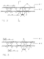
- figure 1 Apart from the glue stations 3', 3'' the schematic representation of figure 1 is also applicable to known methods for the production of honeycomb cores. How the glue pattern according to the prior art will look like for a honeycomb core to be made with cells with an adhering side of 12 mm and a length h 1 (the largest distance between two consecutive plates) of 37 mm, is shown in figure 2. In an alternative embodiment the adhering side and the length h 1 are 11 mm and 25 mm, respectively. On the top paper plate W1 with a thickness of 0,2 mm glue strips 20 are applied which have a nominal width b1 of 11 mm and are spaced at an interspace b2 of twice a bridging side and once an adhering side, in this case 74 mm.
- glue strips 21 are applied which are likewise 11 mm wide and are spaced at a distance of 74 mm.
- the glue strip will expand laterally somewhat and the plate W1 will be glued over strips of approximately 12 mm in width to the lower side of the plate W1.
- the plates W1 and W2 are included in the plate stack, and are then pulled apart in the directions X, the plates W1 and W2 will thus remain glued to each other at the location of the glue strip, thus over an area of 12 mm, and the adjacent parts will rotate relatively in directions T 1 T 2 and then form the inclined bridging sides of the honeycomb cells. This has been shown schematically in an exaggerated way with broken lines.
- each glue strip is replaced by one pair of glue tracks 30, which have a width b3 of 3 mm and are spaced at an interspacing b4 of 5 mm.
- the glue tracks of adjacent adhering sides are again at a mutual distance b5 of 74 mm.
- On the plate W2 similar glue tracks 31 are applied, however in a centrally staggered manner.
- the glue tracks nearest each other in a horizontal sense which are located at different plates, are at a mutual distance which is equal to the corresponding distance in the glue pattern according to figure 2. After pressing the glue tracks are each widened on both sides to 4 mm wide tracks, with an interspacing of 4 mm.
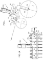
- FIG. 4A a schematic side view is shown of a possible embodiment of the glue station 3' (and glue station 3'', not shown) .
- the glue station 3' of which a part which forms a group of glue spout nozzles is shown here, is arranged above the web W1 which is rolled off roller 1' in the direction shown by the arrow. Downstream from the glue station 3' the web W1 is supported by a roller 5'.
- the glue station 3' is suspended in a fixed frame, not shown, by means of bars 101 and contains a glue supply tube 100, which leads to a distribution chamber 102.
- the distribution chamber 102 is provided with a horizontal series of outlets, not shown, which connect to separate glue supply channels 105 feeding glue from the chamber 102 to glue spout nozzles 4', which are formed in the glue block 103, which is attached in such a way onto the chamber 102 by means of screw bolts that no glue can leak out.
- the web W1 is pushed up somewhat by the roller 5', so that the top surface of the web W1 abuts the spout nozzle openings with slight pressure.
- Upstream from there the glue station is provided with a fixed steel bar 108 for guiding the paper web along the spout nozzles to keep the contact pressure as minimal as possible.
- the roller 1' is provided with an angular velocity meter 120 and a supply meter 121.
- the data of both of these is delivered via data line 122 to control means, not shown, in the glue station 3', which can regulate the supply pressure of the glue in response to those data.
- the glue station 3' is composed of a number of the groups shown. Each group can contain 16 glue spout nozzles and can have a width of 420 mm.
- connection 110 On the side the glue group shown in figure 4A is provided with a connection 110 with valve 111, on to which a tube for a cleaning agent can be connected.
Landscapes
- Laminated Bodies (AREA)
- Making Paper Articles (AREA)
- Catalysts (AREA)
- Application Of Or Painting With Fluid Materials (AREA)
Claims (8)
- Verfahren zur Herstellung eines wabenförmigen Kernes, geeignet um beispielsweise in eine Wabenplatte aufgenommen zu werden, in welchem Bahnen oder Platten (W1, W2) formbares Material, insbesondere Zellulosematerial wie beispielsweise Papier oder Karton, mit wohl oder nicht sich durchgehend erstreckenden Klebestreifen versehen werden, in welchem für jede zwei aufeinander zu klebenden Platten, welche Platten möglicherweise von Bahnen herrühren, die Klebestreifen auf Flächen davon mit dergleichen Orientierung einander gegenüber regelmäßig seitlich versprungen gelegen sind und in welchem die Platten aufeinander gepreßt werden um sie örtlich aufeinanderkleben zu lassen, in welchem die Klebestreifen mittels Klebespritzdüsen aufgetragen werden, dadurch gekennzeichnet, daß die Klebestreifen (30, 31) jeder aus zwei seitlich auf Abstand voneinander gelegenen Klebespuren aufgebaut sind, die mit ihren entgegengesetzten Längsrändern in einem der Größenordnung der erwünschten Haftseite einer Wabenzelle entsprechenden Abstand voneinander gelegen sind.
- Verfahren nach Anspruch 1, in welchem die Klebespuren eines Klebestreifens (30, 31) in einem seitlichen Zwischenabstand (b4, b4') in der Größenordnung der Klebespurbreite (b3, b3') voneinander liegen.
- Verfahren nach einem der vorgehenden Ansprüche, in welchem in seitlicher Richtung die Dicke (b3, b3') der Klebespuren ungefähr 2 bis 4 mm beträgt.
- Verfahren nach einem der vorgehenden Ansprüche, in welchem der Abstand zwischen zwei in seitlicher Richtung benachbarten Klebestreifen, wovon einer auf der einen Platte (W2) und der andere auf die darauf aufzustellende andere Platte (W1) gelegt wird, mindestens nahezu mit der erwünschten überbrückenden Seite der Wabenzelle übereinstimmt.
- Vorrichtung zur Benutzung während der Ausführung des Verfahrens nach einem der vorhergehenden Ansprüche, mit einer oberhalb der für den Wabenkern zu benutzenden Platten angeordneten Klebestation (3'), mit einer Reihe seitlich nebeneinander aufgestellten Klebespritzdüsen (4') und einem Primärklebezufuhrmittel (100) dafür, wobei die Klebespritzdüsen gruppenweise mit dem Primärklebezufuhrmittel mittels Sekundärklebezufuhrmittel (102) verbunden sind, wobei die Sekundärklebezufuhrmittel mit selektiv betätigbaren Ventilen (104) zur Klebedurchlauf oder nicht versehen sind, wobei das Primärklebezufuhrmittel (100) vorzugsweise mit einem selektiv betätigbaren Klebedruckregler versehen ist.
- Vorrichtung nach Anspruch 5, weiterhin mit Mitteln (120) zur Messung der Geschwindigkeit der an der Klebestation (3') vorbei geführten Platten, wobei der Klebedruckregler in Ansprechung auf die Meßdaten der Geschwindigkeitsmeßmittel betätigbar ist.
- Vorrichtung nach Anspruch 5 oder 6, wobei innerhalb jeder Gruppe Klebespritzdüsen die Klebespritzdüsen (4') mit den Sekundärklebezufuhrmittel (102) mittels Tertiärklebezufuhrmittel (105) verbunden sind, wobei die Tertiärklebezufuhrmittel als eine Reihe parallel aufgestellte und zumindest nahezu untereinander gleich bemessene Klebezufuhrröhre gebildet sind.
- Wabenkern, durch eine Anzahl aus formbarem Material wie beispielsweise Papier oder Karton hergestellten Streifen, die mit Klebestoff aneinander gehaftet sind, gebildet, in welchem Klebstoff lediglich an der Stelle der Ecken der Wabenzellen angebracht ist.
Applications Claiming Priority (3)
| Application Number | Priority Date | Filing Date | Title |
|---|---|---|---|
| NL9500039 | 1995-01-09 | ||
| NL9500039A NL9500039A (nl) | 1995-01-09 | 1995-01-09 | Werkwijze en inrichting voor het vormen van een honingraatvormige kern voor honingraatpanelen. |
| PCT/NL1996/000011 WO1996021554A1 (en) | 1995-01-09 | 1996-01-08 | Method and apparatus for forming a honeycomb-shaped core for honeycomb panels |
Publications (2)
| Publication Number | Publication Date |
|---|---|
| EP0802855A1 EP0802855A1 (de) | 1997-10-29 |
| EP0802855B1 true EP0802855B1 (de) | 1998-10-14 |
Family
ID=19865432
Family Applications (1)
| Application Number | Title | Priority Date | Filing Date |
|---|---|---|---|
| EP96901576A Expired - Lifetime EP0802855B1 (de) | 1995-01-09 | 1996-01-08 | Verfahren und vorrichtung zur herstellung eines wabenförmigen kernes für wabenförmige verbundplatten |
Country Status (19)
| Country | Link |
|---|---|
| US (1) | US6059911A (de) |
| EP (1) | EP0802855B1 (de) |
| JP (1) | JPH10511904A (de) |
| CN (1) | CN1173844A (de) |
| AT (1) | ATE172148T1 (de) |
| AU (1) | AU4591096A (de) |
| BR (1) | BR9606734A (de) |
| CA (1) | CA2209911A1 (de) |
| CZ (1) | CZ217997A3 (de) |
| DE (1) | DE69600789T2 (de) |
| ES (1) | ES2127000T3 (de) |
| FI (1) | FI972920L (de) |
| HU (1) | HUP9801239A3 (de) |
| NL (1) | NL9500039A (de) |
| NO (1) | NO973200L (de) |
| PL (1) | PL321281A1 (de) |
| SK (1) | SK94197A3 (de) |
| TR (1) | TR199700730T1 (de) |
| WO (1) | WO1996021554A1 (de) |
Families Citing this family (5)
| Publication number | Priority date | Publication date | Assignee | Title |
|---|---|---|---|---|
| DE102007057820C5 (de) * | 2007-11-30 | 2020-07-16 | Windmöller & Hölscher Kg | Gegenlage Düsenbeleimung |
| NZ571716A (en) | 2008-10-01 | 2010-02-26 | Corcel Ip Ltd | Forming layered board by placing layers successively between two vertical pressure plates which hold layers |
| CN102873912A (zh) * | 2012-10-29 | 2013-01-16 | 费钧 | 一种柔性支撑体的制造方法 |
| CN112060693B (zh) * | 2020-08-25 | 2023-04-07 | 哈尔滨乾行达科技有限公司 | 一种制造蜂窝结构的方法 |
| CN113211886A (zh) * | 2021-04-13 | 2021-08-06 | 岳西县汇达包装制品有限公司 | 一种凳支撑体生产设备 |
Family Cites Families (7)
| Publication number | Priority date | Publication date | Assignee | Title |
|---|---|---|---|---|
| FR1265535A (fr) * | 1960-07-22 | 1961-06-30 | Dufaylite Dev Ltd | Appareil de production de structures cellulaires en nids d'abeilles |
| US3218217A (en) * | 1962-10-15 | 1965-11-16 | Robert C Geschwender | Apparatus for making cellular material |
| US3535190A (en) * | 1966-05-20 | 1970-10-20 | Continental Can Co | Apparatus for making honeycomb structures |
| US3713954A (en) * | 1970-08-03 | 1973-01-30 | Union Camp Corp | Honeycomb making machine |
| US3979252A (en) * | 1973-12-21 | 1976-09-07 | The Hoyt Corporation | Apparatus for manufacturing cellular structures |
| DE3820718C1 (de) * | 1988-06-18 | 1989-05-11 | Hans Aesch Ch Schmidlin | |
| US5482750A (en) * | 1991-01-02 | 1996-01-09 | Hunter Douglas Inc. | Multiple cell honeycomb insulating panel and method of hanging |
-
1995
- 1995-01-09 NL NL9500039A patent/NL9500039A/nl not_active Application Discontinuation
-
1996
- 1996-01-08 ES ES96901576T patent/ES2127000T3/es not_active Expired - Lifetime
- 1996-01-08 PL PL96321281A patent/PL321281A1/xx unknown
- 1996-01-08 CA CA002209911A patent/CA2209911A1/en not_active Abandoned
- 1996-01-08 JP JP8521571A patent/JPH10511904A/ja active Pending
- 1996-01-08 FI FI972920A patent/FI972920L/fi unknown
- 1996-01-08 BR BR9606734A patent/BR9606734A/pt not_active Application Discontinuation
- 1996-01-08 CN CN96191849A patent/CN1173844A/zh active Pending
- 1996-01-08 EP EP96901576A patent/EP0802855B1/de not_active Expired - Lifetime
- 1996-01-08 US US08/860,951 patent/US6059911A/en not_active Expired - Fee Related
- 1996-01-08 SK SK941-97A patent/SK94197A3/sk unknown
- 1996-01-08 WO PCT/NL1996/000011 patent/WO1996021554A1/en not_active Ceased
- 1996-01-08 AT AT96901576T patent/ATE172148T1/de not_active IP Right Cessation
- 1996-01-08 DE DE69600789T patent/DE69600789T2/de not_active Expired - Fee Related
- 1996-01-08 CZ CZ972179A patent/CZ217997A3/cs unknown
- 1996-01-08 HU HU9801239A patent/HUP9801239A3/hu unknown
- 1996-01-08 TR TR97/00730T patent/TR199700730T1/xx unknown
- 1996-01-08 AU AU45910/96A patent/AU4591096A/en not_active Abandoned
-
1997
- 1997-07-09 NO NO973200A patent/NO973200L/no not_active Application Discontinuation
Also Published As
| Publication number | Publication date |
|---|---|
| FI972920A7 (fi) | 1997-09-08 |
| MX9705179A (es) | 1998-07-31 |
| EP0802855A1 (de) | 1997-10-29 |
| ES2127000T3 (es) | 1999-04-01 |
| DE69600789D1 (de) | 1998-11-19 |
| TR199700730T1 (xx) | 1998-03-21 |
| HUP9801239A2 (hu) | 1998-09-28 |
| WO1996021554A1 (en) | 1996-07-18 |
| HUP9801239A3 (en) | 1999-03-01 |
| JPH10511904A (ja) | 1998-11-17 |
| ATE172148T1 (de) | 1998-10-15 |
| CN1173844A (zh) | 1998-02-18 |
| FI972920A0 (fi) | 1997-07-09 |
| FI972920L (fi) | 1997-09-08 |
| US6059911A (en) | 2000-05-09 |
| DE69600789T2 (de) | 1999-05-27 |
| AU4591096A (en) | 1996-07-31 |
| PL321281A1 (en) | 1997-11-24 |
| BR9606734A (pt) | 1998-01-13 |
| CZ217997A3 (cs) | 1998-01-14 |
| NL9500039A (nl) | 1996-08-01 |
| CA2209911A1 (en) | 1996-07-18 |
| NO973200D0 (no) | 1997-07-09 |
| NO973200L (no) | 1997-09-09 |
| SK94197A3 (en) | 1998-07-08 |
Similar Documents
| Publication | Publication Date | Title |
|---|---|---|
| US4369025A (en) | Apparatus for manufacturing elements by means of a hardenable binding agent to which a liquid is added | |
| US5727370A (en) | Apparatus and method for producing foam cushions utilizing flexible foam mixing chamber | |
| AU658508B2 (en) | A light control window covering and a process and apparatus for fabricating honeycomb material | |
| IT1312500B1 (it) | Apparechiatura per fabbricare una copertura regolabile per aperturearchitettoniche | |
| EP0802855B1 (de) | Verfahren und vorrichtung zur herstellung eines wabenförmigen kernes für wabenförmige verbundplatten | |
| DE3835302A1 (de) | Drehschneidgesenk- und lamellierungsverfahren und vorrichtung zur durchfuehrung | |
| EP0008225B1 (de) | Ein Verfahren und eine Vorrichtung zur Fertigung krümmungsfreier Wellpappe | |
| EP0347729B1 (de) | Verfahren und Vorrichtung zur Herstellung eines endlosen Wabenbandes | |
| CZ341495A3 (en) | Panel made of mineral wool, process of its manufacture and apparatus for making the same | |
| US5975180A (en) | Machine for the production of panels including specified displacement means | |
| MXPA97005179A (en) | Method and apparatus to form an alveolar soul for alma alveo panels | |
| CN212292203U (zh) | 一种地板覆离型纸静音垫生产线 | |
| US3535190A (en) | Apparatus for making honeycomb structures | |
| JPH02122921A (ja) | 薄いストリツプまたはウエブ用のコルゲートを長さ方向に付ける装置 | |
| JP3495425B2 (ja) | コルゲートマシン | |
| CN110820089A (zh) | 一种适用于气压棉箱喂棉机的双向同时喂入纤维装置 | |
| WO1997026792A1 (en) | Handling materials | |
| CH663596A5 (de) | Vorrichtung zum foerdern von hochkant stehenden glasscheiben. | |
| AU2005201822B2 (en) | A method of manufacturing biodegradable packaging material and apparatus therefor | |
| US20240408638A1 (en) | Liquid device | |
| JPS5916617A (ja) | 厚鋼板のオンライン冷却装置 | |
| DE2355797B2 (de) | Presse zur Ausübung einer Flächenpressung | |
| US20050092426A1 (en) | System and method for manufacturing filling strips configured for use with a corrugated member | |
| WO2011020146A1 (en) | Profiled plasterboard | |
| US3819453A (en) | Apparatus for corrugating a web of thin material such as paper, in a continuous process |
Legal Events
| Date | Code | Title | Description |
|---|---|---|---|
| PUAI | Public reference made under article 153(3) epc to a published international application that has entered the european phase |
Free format text: ORIGINAL CODE: 0009012 |
|
| 17P | Request for examination filed |
Effective date: 19970808 |
|
| AK | Designated contracting states |
Kind code of ref document: A1 Designated state(s): AT BE CH DE DK ES FR GB GR IE IT LI LU NL PT SE |
|
| 17Q | First examination report despatched |
Effective date: 19971022 |
|
| GRAG | Despatch of communication of intention to grant |
Free format text: ORIGINAL CODE: EPIDOS AGRA |
|
| GRAG | Despatch of communication of intention to grant |
Free format text: ORIGINAL CODE: EPIDOS AGRA |
|
| GRAH | Despatch of communication of intention to grant a patent |
Free format text: ORIGINAL CODE: EPIDOS IGRA |
|
| GRAH | Despatch of communication of intention to grant a patent |
Free format text: ORIGINAL CODE: EPIDOS IGRA |
|
| GRAA | (expected) grant |
Free format text: ORIGINAL CODE: 0009210 |
|
| AK | Designated contracting states |
Kind code of ref document: B1 Designated state(s): AT BE CH DE DK ES FR GB GR IE IT LI LU NL PT SE |
|
| PG25 | Lapsed in a contracting state [announced via postgrant information from national office to epo] |
Ref country code: GR Free format text: LAPSE BECAUSE OF NON-PAYMENT OF DUE FEES Effective date: 19981014 |
|
| REF | Corresponds to: |
Ref document number: 172148 Country of ref document: AT Date of ref document: 19981015 Kind code of ref document: T |
|
| REG | Reference to a national code |
Ref country code: CH Ref legal event code: EP |
|
| REF | Corresponds to: |
Ref document number: 69600789 Country of ref document: DE Date of ref document: 19981119 |
|
| REG | Reference to a national code |
Ref country code: IE Ref legal event code: FG4D |
|
| PG25 | Lapsed in a contracting state [announced via postgrant information from national office to epo] |
Ref country code: LU Free format text: LAPSE BECAUSE OF NON-PAYMENT OF DUE FEES Effective date: 19990108 |
|
| PG25 | Lapsed in a contracting state [announced via postgrant information from national office to epo] |
Ref country code: SE Free format text: LAPSE BECAUSE OF FAILURE TO SUBMIT A TRANSLATION OF THE DESCRIPTION OR TO PAY THE FEE WITHIN THE PRESCRIBED TIME-LIMIT Effective date: 19990114 Ref country code: PT Free format text: LAPSE BECAUSE OF FAILURE TO SUBMIT A TRANSLATION OF THE DESCRIPTION OR TO PAY THE FEE WITHIN THE PRESCRIBED TIME-LIMIT Effective date: 19990114 Ref country code: DK Free format text: LAPSE BECAUSE OF FAILURE TO SUBMIT A TRANSLATION OF THE DESCRIPTION OR TO PAY THE FEE WITHIN THE PRESCRIBED TIME-LIMIT Effective date: 19990114 |
|
| ET | Fr: translation filed | ||
| REG | Reference to a national code |
Ref country code: ES Ref legal event code: FG2A Ref document number: 2127000 Country of ref document: ES Kind code of ref document: T3 |
|
| PLBE | No opposition filed within time limit |
Free format text: ORIGINAL CODE: 0009261 |
|
| STAA | Information on the status of an ep patent application or granted ep patent |
Free format text: STATUS: NO OPPOSITION FILED WITHIN TIME LIMIT |
|
| 26N | No opposition filed | ||
| PGFP | Annual fee paid to national office [announced via postgrant information from national office to epo] |
Ref country code: IE Payment date: 20010109 Year of fee payment: 6 |
|
| PGFP | Annual fee paid to national office [announced via postgrant information from national office to epo] |
Ref country code: ES Payment date: 20010116 Year of fee payment: 6 |
|
| PGFP | Annual fee paid to national office [announced via postgrant information from national office to epo] |
Ref country code: AT Payment date: 20010122 Year of fee payment: 6 |
|
| PGFP | Annual fee paid to national office [announced via postgrant information from national office to epo] |
Ref country code: CH Payment date: 20010126 Year of fee payment: 6 |
|
| PGFP | Annual fee paid to national office [announced via postgrant information from national office to epo] |
Ref country code: BE Payment date: 20010130 Year of fee payment: 6 |
|
| REG | Reference to a national code |
Ref country code: GB Ref legal event code: IF02 |
|
| PG25 | Lapsed in a contracting state [announced via postgrant information from national office to epo] |
Ref country code: IE Free format text: LAPSE BECAUSE OF NON-PAYMENT OF DUE FEES Effective date: 20020108 Ref country code: AT Free format text: LAPSE BECAUSE OF NON-PAYMENT OF DUE FEES Effective date: 20020108 |
|
| PG25 | Lapsed in a contracting state [announced via postgrant information from national office to epo] |
Ref country code: ES Free format text: LAPSE BECAUSE OF NON-PAYMENT OF DUE FEES Effective date: 20020109 |
|
| PG25 | Lapsed in a contracting state [announced via postgrant information from national office to epo] |
Ref country code: LI Free format text: LAPSE BECAUSE OF NON-PAYMENT OF DUE FEES Effective date: 20020131 Ref country code: CH Free format text: LAPSE BECAUSE OF NON-PAYMENT OF DUE FEES Effective date: 20020131 Ref country code: BE Free format text: LAPSE BECAUSE OF NON-PAYMENT OF DUE FEES Effective date: 20020131 |
|
| BERE | Be: lapsed |
Owner name: BESIN B.V. Effective date: 20020131 |
|
| REG | Reference to a national code |
Ref country code: CH Ref legal event code: PL |
|
| REG | Reference to a national code |
Ref country code: IE Ref legal event code: MM4A |
|
| PGFP | Annual fee paid to national office [announced via postgrant information from national office to epo] |
Ref country code: NL Payment date: 20030131 Year of fee payment: 8 |
|
| PGFP | Annual fee paid to national office [announced via postgrant information from national office to epo] |
Ref country code: GB Payment date: 20031217 Year of fee payment: 9 |
|
| PGFP | Annual fee paid to national office [announced via postgrant information from national office to epo] |
Ref country code: FR Payment date: 20040113 Year of fee payment: 9 |
|
| PGFP | Annual fee paid to national office [announced via postgrant information from national office to epo] |
Ref country code: DE Payment date: 20040316 Year of fee payment: 9 |
|
| PG25 | Lapsed in a contracting state [announced via postgrant information from national office to epo] |
Ref country code: NL Free format text: LAPSE BECAUSE OF NON-PAYMENT OF DUE FEES Effective date: 20040801 |
|
| NLV4 | Nl: lapsed or anulled due to non-payment of the annual fee |
Effective date: 20040801 |
|
| PG25 | Lapsed in a contracting state [announced via postgrant information from national office to epo] |
Ref country code: IT Free format text: LAPSE BECAUSE OF NON-PAYMENT OF DUE FEES;WARNING: LAPSES OF ITALIAN PATENTS WITH EFFECTIVE DATE BEFORE 2007 MAY HAVE OCCURRED AT ANY TIME BEFORE 2007. THE CORRECT EFFECTIVE DATE MAY BE DIFFERENT FROM THE ONE RECORDED. Effective date: 20050108 Ref country code: GB Free format text: LAPSE BECAUSE OF NON-PAYMENT OF DUE FEES Effective date: 20050108 |
|
| PG25 | Lapsed in a contracting state [announced via postgrant information from national office to epo] |
Ref country code: DE Free format text: LAPSE BECAUSE OF NON-PAYMENT OF DUE FEES Effective date: 20050802 |
|
| GBPC | Gb: european patent ceased through non-payment of renewal fee |
Effective date: 20050108 |
|
| PG25 | Lapsed in a contracting state [announced via postgrant information from national office to epo] |
Ref country code: FR Free format text: LAPSE BECAUSE OF NON-PAYMENT OF DUE FEES Effective date: 20050930 |
|
| REG | Reference to a national code |
Ref country code: FR Ref legal event code: ST |