EP0803020B1 - Securing of reinforcing strips - Google Patents
Securing of reinforcing strips Download PDFInfo
- Publication number
- EP0803020B1 EP0803020B1 EP95938340A EP95938340A EP0803020B1 EP 0803020 B1 EP0803020 B1 EP 0803020B1 EP 95938340 A EP95938340 A EP 95938340A EP 95938340 A EP95938340 A EP 95938340A EP 0803020 B1 EP0803020 B1 EP 0803020B1
- Authority
- EP
- European Patent Office
- Prior art keywords
- wall
- lamella
- reinforcement
- concrete
- reinforced
- Prior art date
- Legal status (The legal status is an assumption and is not a legal conclusion. Google has not performed a legal analysis and makes no representation as to the accuracy of the status listed.)
- Expired - Lifetime
Links
- 230000003014 reinforcing effect Effects 0.000 title claims abstract description 22
- 238000000034 method Methods 0.000 claims abstract description 11
- 230000002787 reinforcement Effects 0.000 claims description 59
- 241000446313 Lamella Species 0.000 claims description 55
- 239000004567 concrete Substances 0.000 claims description 49
- 229910000831 Steel Inorganic materials 0.000 claims description 16
- 239000010959 steel Substances 0.000 claims description 16
- 239000000463 material Substances 0.000 claims description 10
- 239000000853 adhesive Substances 0.000 claims description 8
- 230000001070 adhesive effect Effects 0.000 claims description 8
- 229920000642 polymer Polymers 0.000 claims description 5
- XEEYBQQBJWHFJM-UHFFFAOYSA-N Iron Chemical compound [Fe] XEEYBQQBJWHFJM-UHFFFAOYSA-N 0.000 claims description 4
- 239000004570 mortar (masonry) Substances 0.000 claims description 4
- XAGFODPZIPBFFR-UHFFFAOYSA-N aluminium Chemical compound [Al] XAGFODPZIPBFFR-UHFFFAOYSA-N 0.000 claims description 2
- 229910052782 aluminium Inorganic materials 0.000 claims description 2
- 239000011083 cement mortar Substances 0.000 claims description 2
- 239000003365 glass fiber Substances 0.000 claims description 2
- 229910052742 iron Inorganic materials 0.000 claims description 2
- 241000531908 Aramides Species 0.000 claims 1
- OKTJSMMVPCPJKN-UHFFFAOYSA-N Carbon Chemical compound [C] OKTJSMMVPCPJKN-UHFFFAOYSA-N 0.000 claims 1
- 239000004411 aluminium Substances 0.000 claims 1
- 229920003235 aromatic polyamide Polymers 0.000 claims 1
- 229910052799 carbon Inorganic materials 0.000 claims 1
- 239000004568 cement Substances 0.000 claims 1
- 239000007769 metal material Substances 0.000 claims 1
- 239000002986 polymer concrete Substances 0.000 claims 1
- 239000002990 reinforced plastic Substances 0.000 claims 1
- 238000004873 anchoring Methods 0.000 description 23
- 238000012360 testing method Methods 0.000 description 13
- 239000003822 epoxy resin Substances 0.000 description 8
- 229920000647 polyepoxide Polymers 0.000 description 8
- 239000011150 reinforced concrete Substances 0.000 description 6
- 229920000049 Carbon (fiber) Polymers 0.000 description 5
- 239000004917 carbon fiber Substances 0.000 description 5
- 238000010276 construction Methods 0.000 description 5
- VNWKTOKETHGBQD-UHFFFAOYSA-N methane Chemical compound C VNWKTOKETHGBQD-UHFFFAOYSA-N 0.000 description 5
- 238000011160 research Methods 0.000 description 5
- 230000035882 stress Effects 0.000 description 5
- 238000005452 bending Methods 0.000 description 4
- 239000002131 composite material Substances 0.000 description 3
- 230000007797 corrosion Effects 0.000 description 3
- 238000005260 corrosion Methods 0.000 description 3
- 238000010586 diagram Methods 0.000 description 3
- 238000004026 adhesive bonding Methods 0.000 description 2
- 230000015572 biosynthetic process Effects 0.000 description 2
- 239000004918 carbon fiber reinforced polymer Substances 0.000 description 2
- 230000000694 effects Effects 0.000 description 2
- 238000004453 electron probe microanalysis Methods 0.000 description 2
- 238000005516 engineering process Methods 0.000 description 2
- 206010016256 fatigue Diseases 0.000 description 2
- 239000000835 fiber Substances 0.000 description 2
- 238000000227 grinding Methods 0.000 description 2
- LNEPOXFFQSENCJ-UHFFFAOYSA-N haloperidol Chemical compound C1CC(O)(C=2C=CC(Cl)=CC=2)CCN1CCCC(=O)C1=CC=C(F)C=C1 LNEPOXFFQSENCJ-UHFFFAOYSA-N 0.000 description 2
- KJPHTXTWFHVJIG-UHFFFAOYSA-N n-ethyl-2-[(6-methoxypyridin-3-yl)-(2-methylphenyl)sulfonylamino]-n-(pyridin-3-ylmethyl)acetamide Chemical compound C=1C=C(OC)N=CC=1N(S(=O)(=O)C=1C(=CC=CC=1)C)CC(=O)N(CC)CC1=CC=CN=C1 KJPHTXTWFHVJIG-UHFFFAOYSA-N 0.000 description 2
- 238000009418 renovation Methods 0.000 description 2
- 239000000243 solution Substances 0.000 description 2
- 239000004593 Epoxy Substances 0.000 description 1
- 230000032683 aging Effects 0.000 description 1
- 230000005540 biological transmission Effects 0.000 description 1
- 239000000969 carrier Substances 0.000 description 1
- 230000001419 dependent effect Effects 0.000 description 1
- 238000013461 design Methods 0.000 description 1
- 238000005553 drilling Methods 0.000 description 1
- 239000011152 fibreglass Substances 0.000 description 1
- 238000009472 formulation Methods 0.000 description 1
- 229920006253 high performance fiber Polymers 0.000 description 1
- 238000003780 insertion Methods 0.000 description 1
- 230000037431 insertion Effects 0.000 description 1
- 238000011835 investigation Methods 0.000 description 1
- 238000003801 milling Methods 0.000 description 1
- 239000000203 mixture Substances 0.000 description 1
- 238000012986 modification Methods 0.000 description 1
- 230000004048 modification Effects 0.000 description 1
- 238000005192 partition Methods 0.000 description 1
- 229920001225 polyester resin Polymers 0.000 description 1
- 239000004645 polyester resin Substances 0.000 description 1
- 229920001296 polysiloxane Polymers 0.000 description 1
- 239000004814 polyurethane Substances 0.000 description 1
- 229920002635 polyurethane Polymers 0.000 description 1
- 230000002028 premature Effects 0.000 description 1
- 238000009419 refurbishment Methods 0.000 description 1
- 238000010008 shearing Methods 0.000 description 1
- 230000003068 static effect Effects 0.000 description 1
- 229920001169 thermoplastic Polymers 0.000 description 1
- 239000004416 thermosoftening plastic Substances 0.000 description 1
Images




Classifications
-
- E—FIXED CONSTRUCTIONS
- E04—BUILDING
- E04G—SCAFFOLDING; FORMS; SHUTTERING; BUILDING IMPLEMENTS OR AIDS, OR THEIR USE; HANDLING BUILDING MATERIALS ON THE SITE; REPAIRING, BREAKING-UP OR OTHER WORK ON EXISTING BUILDINGS
- E04G23/00—Working measures on existing buildings
- E04G23/02—Repairing, e.g. filling cracks; Restoring; Altering; Enlarging
- E04G23/0218—Increasing or restoring the load-bearing capacity of building construction elements
-
- E—FIXED CONSTRUCTIONS
- E04—BUILDING
- E04G—SCAFFOLDING; FORMS; SHUTTERING; BUILDING IMPLEMENTS OR AIDS, OR THEIR USE; HANDLING BUILDING MATERIALS ON THE SITE; REPAIRING, BREAKING-UP OR OTHER WORK ON EXISTING BUILDINGS
- E04G23/00—Working measures on existing buildings
- E04G23/02—Repairing, e.g. filling cracks; Restoring; Altering; Enlarging
- E04G23/0218—Increasing or restoring the load-bearing capacity of building construction elements
- E04G2023/0251—Increasing or restoring the load-bearing capacity of building construction elements by using fiber reinforced plastic elements
-
- E—FIXED CONSTRUCTIONS
- E04—BUILDING
- E04G—SCAFFOLDING; FORMS; SHUTTERING; BUILDING IMPLEMENTS OR AIDS, OR THEIR USE; HANDLING BUILDING MATERIALS ON THE SITE; REPAIRING, BREAKING-UP OR OTHER WORK ON EXISTING BUILDINGS
- E04G23/00—Working measures on existing buildings
- E04G23/02—Repairing, e.g. filling cracks; Restoring; Altering; Enlarging
- E04G23/0218—Increasing or restoring the load-bearing capacity of building construction elements
- E04G2023/0251—Increasing or restoring the load-bearing capacity of building construction elements by using fiber reinforced plastic elements
- E04G2023/0255—Increasing or restoring the load-bearing capacity of building construction elements by using fiber reinforced plastic elements whereby the fiber reinforced plastic elements are stressed
- E04G2023/0259—Devices specifically adapted to stress the fiber reinforced plastic elements
-
- E—FIXED CONSTRUCTIONS
- E04—BUILDING
- E04G—SCAFFOLDING; FORMS; SHUTTERING; BUILDING IMPLEMENTS OR AIDS, OR THEIR USE; HANDLING BUILDING MATERIALS ON THE SITE; REPAIRING, BREAKING-UP OR OTHER WORK ON EXISTING BUILDINGS
- E04G23/00—Working measures on existing buildings
- E04G23/02—Repairing, e.g. filling cracks; Restoring; Altering; Enlarging
- E04G23/0218—Increasing or restoring the load-bearing capacity of building construction elements
- E04G2023/0251—Increasing or restoring the load-bearing capacity of building construction elements by using fiber reinforced plastic elements
- E04G2023/0262—Devices specifically adapted for anchoring the fiber reinforced plastic elements, e.g. to avoid peeling off
Definitions
- the present invention relates to an arrangement for reinforcement on a longitudinally extended and / or flat structure or part of the structure by means of at least one on the structure or structural part or masonry slack or pre-stressed lamellar reinforcement, one for carrier functions intended structural part, reinforced with an arrangement, masonry with an arrangement and a method for reinforcing a building or part of a building.
- the reinforcement of concrete structures and masonry by gluing of steel slats, with for example epoxy resin adhesives, can be regarded as standard technology today.
- Shear crack formation Special attention must be paid to the Shear crack formation in the concrete or masonry are given for free. Occurring shear cracks lead to an offset on the reinforced Surface, which is usually a peeling or a Detachment of the reinforcement slats entails.
- the Shear crack formation is therefore also an important design criterion, both in terms of the carrying capacity of the unreinforced part of the building, as well as a possible risk of detachment the subsequently arranged reinforcement slats.
- the object is achieved by means of a Arrangement according to the wording according to claim 1 solved.
- An arrangement for reinforcement on one is proposed longitudinally extended and / or flat structure or structural part limp by means of at least one on the structure or part of the structure or pre-stressed lamellar reinforcement, whereby according to the invention the reinforcement, at least a slat at least at one end in the building or anchored part of the building.
- At least one slat end preferably at least almost continuously bent into the Building or masonry is diverted in order to in Structure or masonry to be anchored.
- the arrangement or anchoring proposed according to the invention one slat end, protruding into the building or masonry, is of course suitable for any known Reinforcement slats, such as steel slats, Glass fiber or carbon fiber reinforced slats, for example made with epoxy resins or polyester resins, extruded reinforcement lamellas from a thermoplastic, Etc.
- Reinforcement slats such as steel slats, Glass fiber or carbon fiber reinforced slats, for example made with epoxy resins or polyester resins, extruded reinforcement lamellas from a thermoplastic, Etc.
- the at least one end of the reinforcement lamella or so both ends of the reinforcing lamella are preferably continuous curved into the structure, each one the recessed end by means of concrete and / or a polymer-reinforced Material, such as in particular an adhesive, can be covered.
- a polymer-reinforced Material such as in particular an adhesive
- Slat end additionally by means of pre-tensioned or not pre-tensioned mechanical fasteners, such as in particular Screws, rivets, pins, loops, and the like in the building or to anchor building part or masonry.
- the arrangement proposed according to the invention is suitable for a structure or part of a structure intended for supporting functions, which with one or more reinforcement slats is reinforced against shear forces. But also for the reinforcement of any building or masonry by means of one or more reinforcement slats, it is advantageous the slat ends, as proposed according to the invention, running into the building or part of the building or masonry to anchor. For example, it is possible when reinforcing masonry in seismic zones the slat ends running into the masonry using GRP slats to anchor, which eliminates the need the slats down to the end of the masonry Concrete slabs or cover slabs for anchoring to extend, which is a significant simplification when applying represents such reinforcing slats.
- Fig. 1 is a reinforced concrete bridge schematically in longitudinal section 1, comprising a concrete slab 3, which supported by two pillars 5 on the respective supports 7 or is held.
- this concrete bridge by means of one arranged between the two supports 7
- Reinforcement lamella 10 has been reinforced.
- the reinforcement slat 10 extends between the two supports 7 and is in its entire length, for example with a Epoxy resin adhesive glued on, also terminal in the area A ', as is customary, the lamella on the concrete slab 3 is glued. It is possible, as in W093 / 20296 suggested using additional straps or steel plates to anchor the slat ends additionally, or against the Press concrete slab 3.
- FIG. 2 shows a push wall 11 of a building, that is in a seismic area. It is the masonry 13 with laterally glued-on reinforcement slats 20 reinforced, the slats usually terminal in the below and above the thrust wall 13 Concrete slabs or the floor and ceiling slabs 15 and 17 are anchored is. Here, for example in area A ", the slat end led into the concrete slab 17, to be anchored in it.
- the creation of this Anchoring is complex and requires a lot of work.
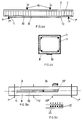
- a concrete beam 3 is analogous to that in longitudinal section shown by Fig. 1, which for the following Experimental setup is used.
- Fig. 4a a concrete beam 3 is analogous to that in longitudinal section shown by Fig. 1, which for the following Experimental setup is used.
- the concrete beam 3 is on the supports 7 and comprises a steel reinforcement 4.
- the concrete beam 3 is 8 on its lower side by means of a CFRP lamella 10, the one End 11 of the slat practically up to the corresponding support 7 'runs, while the opposite slat end 13 from the other supports 7 ".
- Fig. 4b shows the concrete beam from Fig. 4a in cross section.
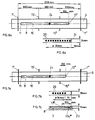
- the experimental arrangement shown in Fig. 5a, shows the reinforcing lamella in top view of the one to be reinforced Concrete beam 3, the one slat end 11 extending up to Support 7 'extends while the opposite Slat end 13 'a distance above the corresponding one Force application point 15 "extends beyond.
- the dimensioning of the Experimental arrangement is shown in the representation of Fig. 5a, the slat end 13 'accordingly by 20cm extends beyond the force introduction point 15 ".
- the measuring points 29 are shown schematically, which on the Slat end 13 'for determining the forces or of the occurring stretch are provided.
- Digit 24 in Fig. 5a marks the center of the concrete beam 3, where also one Measuring point is arranged.
- the slat end 13 ' is conventional and anchored glued to the underside of the concrete beam.
- 6a and 6b show an analog test arrangement, wherein however, the slat end 13 "is 30cm above the corresponding one Force introduction point 15 "extends, and thus closer to the corresponding support 7 ". Again several measuring points are provided in the area of the end 13 ", as well as in the middle at point 24 on the concrete beam 3.
- FIG. 7 shows an experimental arrangement, where now the slat end 13 '"running into the building part is anchored, which in the longitudinal sectional view of Fig. 7c is shown schematically.
- the slat end extends 13 '"again only 20cm above the corresponding one Force introduction point 15 "is also spaced 10 cm apart from the corresponding support 7 ", compared to the Experimental arrangement according to FIGS. 6a and 6b.
- Anchoring the Slat end 13 '" runs along a distance of 10cm, 7c, the continuously curved, in the concrete beam 3rd extending end piece 13a '"schematically shown in longitudinal section is.
- Over the lamella in area 23 was in the Anchoring zone of the end portion 13a '"an epoxy resin mortar applied.
- Fig. 7b there are schematically several Measuring points 29 shown, which are arranged on the lamella 10 have been. Also at position 24 in the middle the concrete beam 3 became a measuring point on the reinforcement lamella 10
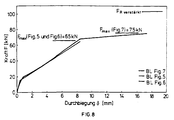
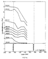
- Fig. 8 now shows in diagram form the deflection of the test vehicle measured in the middle of the beam with the three according to the 5, 6 and 7 used experimental arrangements.
- the deflection ⁇ (mm) is dependent on the one introduced at points 15 Force (KN) represented by bending is shown separately for the three test arrangements.
- Table 1 below shows the measured load resistances, the mean lamella tension in the center of the beam, and the type of failure of the beams for the three test arrangements.
- carrier F max [kNm] ⁇ L (F) [N / mm 2 ] to fail Fig. 5 65 456 (60)
- the maximum load and in particular the maximum slat expansion in the experimental arrangement according to the invention according to FIG. 7 compared to the carriers of the experimental arrangements 5 and 6 can be increased significantly.
- the carrier according to Fig. 5 and 6 show despite different anchorage lengths in the area of the ends 13 'and 13 "a similar behavior. In the middle Carrier area are registered about the same strains. They shear each time the flow load is reached Slats from the slat end.
- Such core drilling For example, a hole diameter of 10 or more cm, depending on how wide the reinforcement slat to be anchored 10 is. After the one running into the building Arranging the slat end 22 can again, as already 3, an anchoring wedge 23 is arranged will.
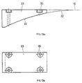
- Such an anchoring wedge is also shown in Fig. 13a and 13b, with additional fastening means now 33 are arranged, for example screws, Bolts, loops, etc. can act.
- Fastening means 33 becomes the anchoring effect of the wedge 23 additionally reinforced on the slat end 22. It shows Fig. 13a the wedge 23 in longitudinal section, while Fig. 13b is a plan view of the wedge 23.
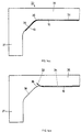
- a concrete structure 32 is shown, such as a support structure for galleries or parking halls, in which construction the ceiling panel 35 and the side wall 37 via a so-called haunch 39 are connected to each other in the corner area. If the bottom now the ceiling 35 by means of a reinforcing lamella 10 14a, it clearly shows that a Anchoring the slat end 13 in the area of the haunch unfavorable is there when tensile forces occur on the reinforcing lamella 10 this is replaced in the corner area 36.
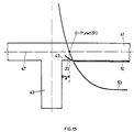
- FIG. 15 finally shows a further structure arrangement, for example again a supporting structure, comprising one Concrete ceiling 41 and a partition or a longitudinal pillar 43, again the ceiling 41 by means of a reinforcing lamella 10 is reinforced.
- a supporting structure comprising one Concrete ceiling 41 and a partition or a longitudinal pillar 43, again the ceiling 41 by means of a reinforcing lamella 10 is reinforced.
- corner area 45 between ceiling 41 and pillar 43, the slat end 22 in accordance with the invention anchored the ceiling running into it.
- the material used can be any, so can be a sheet of iron, steel, aluminum, a reinforced polymer, such as in particular fiberglass reinforced epoxy resin, etc. exist.
Landscapes
- Engineering & Computer Science (AREA)
- Architecture (AREA)
- Civil Engineering (AREA)
- Chemical Kinetics & Catalysis (AREA)
- Electrochemistry (AREA)
- Mechanical Engineering (AREA)
- Chemical & Material Sciences (AREA)
- Structural Engineering (AREA)
- Working Measures On Existing Buildindgs (AREA)
- Reinforcement Elements For Buildings (AREA)
- Bridges Or Land Bridges (AREA)
- Reinforced Plastic Materials (AREA)
- Details Of Garments (AREA)
- Orthopedics, Nursing, And Contraception (AREA)
- Table Devices Or Equipment (AREA)
Abstract
Description
Die vorliegende Erfindung betrifft eine Anordnung zur Verstärkung an einem längsausgedehnten und/oder flächigen Bauwerk oder Bauwerkteil mittels mindestens einer am Bauwerk oder Bauwerkteil oder Mauerwerk schlaff oder vorgespannt angeordneten lamellenartigen Verstärkung, ein für Trägerfunktionen vorgesehenes Bauwerkteil, verstärkt mit einer Anordnung, ein Mauerwerk mit einer Anordnung sowie ein Verfahren zum Verstärken eines Bauwerkes oder Bauwerkteiles.The present invention relates to an arrangement for reinforcement on a longitudinally extended and / or flat structure or part of the structure by means of at least one on the structure or structural part or masonry slack or pre-stressed lamellar reinforcement, one for carrier functions intended structural part, reinforced with an arrangement, masonry with an arrangement and a method for reinforcing a building or part of a building.
Eine solche Anordnung wird z.B. in der Druckschrift DE-A-1 434 075 beschrieben.Such an arrangement is e.g. in the document DE-A-1 434 075.
Seit vielen Jahren beschäftigen sich Forschung und Praxis mit der nachträglichen Verstärkung von Bauwerken, wie insbesondere Stahlbetonkonstruktionen und Mauerwerk durch Anlegen einer zusätzlichen Bewehrung. Die Anfänge dieser Technik werden in J.Bresson, "Nouvelles recherches et applications concernant l'utilisation des collages dans les structures. Beton plaqué.", Annales ITBTP Nr. 278 (1971), Serie Beton, Beton armé Nr. 116, beschrieben und gehen auf die Sechzigerjahre zurück. Dabei hatte Bresson seine Anstrengungen insbesondere auf die Erforschung der Verbundspannung im Bereich der Verankerungen von aufgeklebten Stahllamellen gerichtet.Research and practice have been involved in research for many years the subsequent reinforcement of structures, such as in particular Reinforced concrete structures and masonry by creating one additional reinforcement. The beginnings of this technique are in J.Bresson, "Nouvelles researches and applications concernant l'utilization of the collages in the structures. Concrete plaque. ", Annales ITBTP No. 278 (1971), concrete series, armé concrete No. 116, described and go back to the 1960s. Bresson had his efforts particularly on the Research into bond stress in the area of anchorages directed by glued steel slats.
Seit rund zwanzig Jahren können somit bestehende Bauwerke, wie Stahlbetonkonstruktionen, wie beispielsweise Brücken, Boden- und Deckenplatten, Längsträger und dergleichen oder aber auch unverstärktes Mauerwerk durch nachträgliches Aufkleben von Stahllamellen verstärkt werden.For around twenty years, existing structures, such as reinforced concrete structures such as bridges, Floor and ceiling panels, side members and the like or but also unreinforced masonry through subsequent gluing reinforced by steel slats.
Die Verstärkung von Betonbauwerken und Mauerwerk durch Ankleben von Stahllamellen, mit beispielsweise Epoxidharzklebern, darf heute als Standardtechnik betrachtet werden. The reinforcement of concrete structures and masonry by gluing of steel slats, with for example epoxy resin adhesives, can be regarded as standard technology today.
Es gibt verschiedene Gründe, die eine Verstärkung notwendig machen:
- Erhöhung der Nutzlast,
- Aenderung des statischen Systems, indem beispielsweise tragende Elemente, wie Stützen, nachträglich entfernt werden oder deren Stütz funktionen reduziert werden,
- Verstärkung von ermüdungsgefährdeten Bauteilen,
- Erhöhung der Steifigkeit,
- Schäden an Tragsystemen bzw. Sanierung bestehender Bauwerke und von Mauerwerk, sowie
- Fehlerhafte Berechnung oder Ausführung des Bauwerkes.
- Increase in payload,
- Modification of the static system, for example by subsequently removing load-bearing elements, such as supports, or reducing their support functions,
- Reinforcement of components at risk of fatigue,
- Increase in rigidity,
- Damage to support systems or renovation of existing structures and masonry, as well
- Incorrect calculation or execution of the structure.
Nachträgliche Verstärkungen mit aufgeklebten Stahllamellen haben sich an zahlreichen Bauwerken bewährt, wie beispielsweise in den nachfolgenden Literaturzitaten beschrieben: Ladner, M., Weder, Ch.: "Geklebte Bewehrung im Stahlbetonbau", EMPA Dübendorf, Bericht Nr. 206 (1981); "Verstärkung von Tragkonstruktionen mit geklebter Armierung", Schweiz. Bauzeitung, Sonderdruck aus dem 92. Jahrgang, Heft 10 (1974); "Die Sanierung der Gizenenbrücke über die Muota", Schweiz. Ingenieur & Architekt, Sonderdruck aus Heft 41 (1980).Subsequent reinforcements with glued steel slats have proven themselves on numerous structures, such as described in the following citations: Ladner, M., Weder, Ch .: "Glued reinforcement in reinforced concrete construction", EMPA Dübendorf, Report No. 206 (1981); "Reinforcement of Supporting structures with glued reinforcement ", Switzerland. Bauzeitung, Special print from the 92nd year, issue 10 (1974); "The Refurbishment of the Gizenen Bridge over the Muota ", Switzerland. Engineer & Architekt, reprint from issue 41 (1980).
Diese Verstärkungsverfahren weisen jedoch Nachteile auf. Stahllamellen können nur in kurzen Längen geliefert werden, womit nur die Applikation relativ kurzer Lamellen möglich wird. Somit können Lamellenstösse, die gezwungenermassen notwendig werden, und damit potentielle Schwachstellen nicht vermieden werden. Die umständliche Handhabung von schweren Stahllamellen auf der Baustelle kann ausserdem bei hohen oder schwer zugänglichen Bauwerken erhebliche ausführungstechnische Probleme verursachen. Zudem besteht beim Stahl, auch bei einer sorgfältigen Korrosionsschutzbehandlung, die Gefahr des seitlichen Unterrostens der Lamellen bzw. der Korrosion an der Grenzfläche zwischen Stahl und Beton, was zum Ablösen und somit dem Verlust der Verstärkung führen kann.However, these reinforcement methods have disadvantages. Steel slats can only be supplied in short lengths, with which only the application of relatively short slats is possible becomes. This means that lamella joints are absolutely necessary and therefore not potential weak points be avoided. The cumbersome handling of heavy Steel slats on the construction site can also be used at high or difficult-to-access structures considerable execution Cause problems. There is also steel careful corrosion protection treatment, the risk of lateral rusting of the slats or the corrosion the interface between steel and concrete, causing detachment and thus can lead to the loss of gain.
Entsprechend wurde in der Publikation von U. Meier, "Brückensanierungen mit Hochleistungs-Faserverbundwerkstoffen", Material + Technik, 15. Jahrgang, Heft 4 (1987), und in der Dissertation von H.P. Kaiser, Diss. ETH Nr. 8918 der ETH Zürich (1989), vorgeschlagen, die Stahllamellen durch kohlenstoffaserverstärkte Epoxidharzlamellen zu ersetzen. Lamellen aus diesem Werkstoff zeichnen sich durch eine geringe Rohdichte, sehr hohe Festigkeit, ausgezeichnete Ermüdungseigenschaften und eine hervorragende Korrosionsbeständigkeit aus. Es ist also möglich, anstelle der schweren Stahllamellen leichte, dünne, kohlenstoffaserverstärkte Kunststofflamellen zu verwenden, die quasi endlos im aufgerollten Zustand auf die Baustelle transportiert werden können. Praktische Ermittlungen ergaben, dass Kohlenstoffaserlamellen von 0,5 mm Dicke eine Zugkraft aufzunehmen vermögen, welche der Fliesskraft einer 3mm dicken FE360 Stahllamelle entspricht.Accordingly, the publication by U. Meier, "Bridge renovations with high-performance fiber composite materials ", material + Technik, 15th year, volume 4 (1987), and in the dissertation by H.P. Kaiser, Diss.ETH No. 8918 from ETH Zurich (1989) proposed the steel fins by carbon fiber reinforced To replace epoxy resin fins. Slats off this material is characterized by a low bulk density, very high strength, excellent fatigue properties and excellent corrosion resistance. It is possible instead of the heavy steel slats light, to use thin, carbon fiber reinforced plastic lamellas, the almost endlessly rolled up to the construction site can be transported. Practical investigation showed that carbon fiber lamellae 0.5 mm thick Able to absorb tensile force, which is the flow force of a 3mm thick FE360 steel plate corresponds.
Auch beim Verstärken von Mauerwerk in seismisch gefährdeten Zonen haben sich die erwähnten Kohlenstoffaserlamellen bestens bewährt. Im Bericht 229 der Eidgenössischen Materialprüfungs- und Forschungsanstalt (EMPA), Dübendorf, von G. Schwegler mit dem Titel "Verstärken von Mauerwerk mit Faserverbundwerkstoffen in seismisch gefährdeten Zonen" , wird insbesondere vorgeschlagen, bestehende Mauerwerksschubwände bzw. Wände im Fassadenbereich bei seismisch gefährdeten Gebäuden nachträglich mit Faserverbundlamellen zu verstärken. Damit können Mauerwerke in bezug auf Schub- und Zugfestigkeit, verglichen mit nichtbewehrtem Mauerwerk, entscheidend verstärkt werden. Dabei wird beispielsweise vorgeschlagen, die Verstärkungslamellen diagonal und kreuzweise an einer Schubwand, wie einer Fassadenmauer aufzukleben, wobei es sich gezeigt hat, dass für die Erhöhung des Schubwiderstandes die endständige Lamellenverankerung, beispielsweise in Betonplatten, ausschlaggebend ist.Even when reinforcing masonry in seismically vulnerable Zones have the carbon fiber lamella mentioned best proven. In report 229 of the Federal Materials Testing and Research Institute (EMPA), Dübendorf, by G. Schwegler with the title "Reinforcement of masonry with fiber composite materials in seismic areas " in particular, proposed existing masonry sliding walls or walls in the facade area in seismically endangered buildings subsequently reinforced with fiber composite lamellas. This allows masonry in terms of shear and tensile strength, compared to unreinforced masonry, crucial be reinforced. It is proposed, for example, the reinforcement slats diagonally and crosswise on one Thrust wall, like sticking to a facade wall, taking it has shown that for increasing the thrust resistance the terminal lamella anchoring, for example in concrete slabs, is decisive.
Besondere Beachtung muss in allen geschilderten Fällen der Schubrissbildung im Beton bzw. Mauerwerk geschenkt werden. Auftretende Schubrisse führen zu einem Versatz an der verstärkten Oberfläche, was in der Regel ein Abschälen bzw. ein Ablösen der Verstärkungslamellen nach sich zieht. Die Schubrissbildung ist somit ebenfalls ein wesentliches Bemessungskriterium, sowohl in bezug auf die Tragfähigkeit des unverstärkten Bauwerkteils, wie auch auf eine allfällige Ablösegefahr der nachträglich angeordneten verstärkungslamellen.Special attention must be paid to the Shear crack formation in the concrete or masonry are given for free. Occurring shear cracks lead to an offset on the reinforced Surface, which is usually a peeling or a Detachment of the reinforcement slats entails. The Shear crack formation is therefore also an important design criterion, both in terms of the carrying capacity of the unreinforced part of the building, as well as a possible risk of detachment the subsequently arranged reinforcement slats.
In der internationalen PCT-Anmeldung WO93/20 296 wird ein Verfahren beschrieben, mittels welchem für Tragfunktionen vorgesehene Bauwerksteile gegen auftretende Schubkräfte verstärkt werden, indem die oben erwähnten Verstärkungslamellen je im Endbereich aussen einfassend mittels Spannelementen am Bauwerk angepresst werden, um ein Ablösen zu verhindern. Dabei werden die Lamellen so angeordnet, dass der Abstand vom Lamellenende zum Auflager bzw. den endständig bei Schubwänden angeordneten Betonplatten möglichst klein ist. Die Verankerungszone muss so bemessen sein, dass die Lamellenzugkraft verankert werden kann, und die Weiterleitung der Kraft bis zu einem Auflager bzw. den eine Schubwand einfassenden Betonplatten gewährleistet ist.In the international PCT application WO93 / 20 296 a Described method by means of which for load-bearing functions provided structural parts reinforced against shear forces by using the reinforcement slats mentioned above each enclosing in the end area on the outside by means of clamping elements on Be pressed against the building to prevent detachment. Here the slats are arranged so that the distance from the Slat end to the support or the end with push walls arranged concrete slabs is as small as possible. The anchoring zone must be dimensioned so that the slat tensile force can be anchored, and the transmission of force up to a support or the concrete slabs enclosing a thrust wall is guaranteed.
In der Praxis hat es sich nun aber gezeigt, dass ein Verankern der Verstärkungslamellen im Bereich der Auflager infolge Vouten und Absätzen nicht immer möglich ist, was zu einer Vergrösserung des Abstandes führt. Auch bei der Verstärkung von Schubwänden ist es meistens schwierig und aufwendig, die Verstärkungslamellen in den jeweils oben und unten an diesen Wänden angeordneten Betonplatten zu verankern. Im weiteren ist es aus Handlingsgründen auf Baustellen vorteilhaft, wenn Verstärkungslamellen nicht zu lang sein müssen, was sich aber automatisch ergibt, wenn beispielsweise beim Verstärken von Brücken Verstärkungslamellen sich jeweils von Auflager zu Auflager erstrecken müssen.In practice, however, it has now been shown that anchoring the reinforcement slats in the area of the support as a result Haunches and paragraphs is not always possible, leading to a Increasing the distance leads. Even with reinforcements of push walls, it is mostly difficult and time consuming Reinforcement slats in the top and bottom of these Anchor concrete panels arranged on walls. In the further it is advantageous for handling reasons on construction sites if Reinforcement lamellas do not have to be too long, which is automatically results if, for example, when amplifying Bridges reinforcement lamellae each from support to Bearings must extend.
Es ist daher eine Aufgabe der vorliegenden Erfindung eine Massnahme vorzuschlagen, mittels welcher mit verkürzten Verankerungslängen an Verstärkungslamellen eine weitgehendst gleichbleibende Verstärkung an Bauwerken erzielt werden kann.It is therefore an object of the present invention To propose a measure by means of which shortened anchoring lengths on reinforcement lamellas a largely constant reinforcement can be achieved on buildings.
Erfindungsgemäss wird die gestellte Aufgabe mittels einer
Anordnung gemäss dem wortlaut nach Anspruch 1 gelöst.According to the invention, the object is achieved by means of a
Arrangement according to the wording according to
Vorgeschlagen wird eine Anordnung zur Verstärkung an einem längsausgedehnten und/oder flächigen Bauwerk oder Bauwerkteil mittels mindestens einer am Bauwerk oder Bauwerkteil schlaff oder vorgespannt angeordneten lamellenartigen Verstärkung, wobei erfindungsgemäss die zur Verstärkung dienende, mindestens eine Lamelle wenigstens an einem Ende in das Bauwerk bzw. Bauwerkteil hineinverlaufend verankert ist.An arrangement for reinforcement on one is proposed longitudinally extended and / or flat structure or structural part limp by means of at least one on the structure or part of the structure or pre-stressed lamellar reinforcement, whereby according to the invention the reinforcement, at least a slat at least at one end in the building or anchored part of the building.
Dabei wird vorgeschlagen, dass mindestens das eine Lamellenende, vorzugsweise wenigstens nahezu stetig gebogen, in das Bauwerk bzw. Mauerwerk hineinverlaufend umgelenkt wird, um im Bauwerk oder Mauerwerk verankert zu werden.It is proposed that at least one slat end, preferably at least almost continuously bent into the Building or masonry is diverted in order to in Structure or masonry to be anchored.
Auf diese Art und weise ist es möglich auch mit kurzen Verankerungslängen eine ähnliche oder beinahe gleiche Verstärkung an einem Bauwerk bzw. Mauerwerk zu erreichen, wie mit längeren Verankerungslängen, welche sich dadurch ergeben, dass die Verstärkungslamelle praktisch von Auflager zu Auflager verläuft und ein Verankern der Lamellenenden jeweils im Bereich der Auflager problemlos möglich ist. Versuche, auf welche nachfolgend unter Bezug auf die beigefügten Figuren näher eingegangen wird, haben gezeigt, dass verstärkungslamellen, welche lediglich um eine relativ kurze Verankerungslänge über die Lasteneinleitung hinaus am zu verstärkenden Bauwerk angeordnet und erfindungsgemäss in das Bauwerkteil hineinragend verankert worden sind, eine nahezu gleiche Verstärkung am Bauwerk ergeben, wie wenn das entsprechende Lamellenende bis in den Bereich des Auflagers verankert wird.In this way, it is also possible with short anchorage lengths a similar or almost the same gain to achieve on a building or masonry, as with longer anchorage lengths, which result from that the reinforcement slat practically from support to support runs and anchoring the slat ends in each case Area of the support is easily possible. Try on which below with reference to the accompanying figures have shown that reinforcement slats, which is only by a relatively short anchorage length beyond the introduction of the load to be reinforced Structure arranged and according to the invention in the building part have been anchored in an almost identical way on the structure, as if the corresponding slat end until it is anchored in the area of the support.
Das erfindungsgemäss vorgeschlagene Anordnen bzw. Verankern eines Lamellenendes, in das Bauwerk bzw. Mauerwerk hineinragend, eignet sich selbstverständlich für irgendwelche bekannte Verstärkungslamellen, wie beispielsweise Stahllamellen, Glasfaser- oder Kohlenstoffaser-verstärkte Lamellen, beispielsweise hergestellt mit Epoxidharzen oder Polyesterharzen, extrudierte Verstärkungslamellen aus einem Thermoplasten, etc.The arrangement or anchoring proposed according to the invention one slat end, protruding into the building or masonry, is of course suitable for any known Reinforcement slats, such as steel slats, Glass fiber or carbon fiber reinforced slats, for example made with epoxy resins or polyester resins, extruded reinforcement lamellas from a thermoplastic, Etc.
Das mindestens eine Ende der Verstärkungslamelle oder auch beide Enden der Verstärkungslamelle sind vorzugsweise stetig gebogen in das Bauwerk hineinverlaufend eingelassen, wobei je das eingelassene Ende mittels Beton und/oder eines Polymer-verstärkten Materials, wie insbesondere eines Klebstoffes, überdeckt sein kann. Im Falle, beispielsweise von Kohlenstoffaser-verstärkten Epoxidharzen, ist es vorteilhaft einen Epoxidmörtel bzw. ein Epoxidharz-verstärktes Betonpolymer zu verwenden, um das im Mauerwerk bzw. Beton eingelassene Ende der Lamelle zu verankern bzw. zu überdecken.The at least one end of the reinforcement lamella or so both ends of the reinforcing lamella are preferably continuous curved into the structure, each one the recessed end by means of concrete and / or a polymer-reinforced Material, such as in particular an adhesive, can be covered. In the case, for example of carbon fiber reinforced Epoxy resins, it is advantageous to use an epoxy mortar or an epoxy-reinforced concrete polymer use around the end embedded in the masonry or concrete to anchor or cover the slat.
Selbstverständlich ist es auch möglich das in das Mauerwerk bzw. Betonbauwerk hineinragende Lamellenende zusätzlich, wie in der WO93/20296 vorgeschlagen, mit einem platten-, lamellen- oder gurtenartigen Element gegen das Bauwerk bzw. das Bauwerkteil zu pressen, um so eine weitere Verstärkung gegen auftretende Schubkräfte zu erreichen. Dazu eignet sich beispielsweise auch ein das Lamellenende überdeckender Keil.Of course it is also possible to put it into the masonry or concrete structure protruding slat end additionally, such as proposed in WO93 / 20296, with a plate, lamella or belt-like element against the building or the To press the structural part in order to further reinforce it to achieve the thrust that occurs. This is suitable, for example also a wedge covering the slat end.
Anstelle dieser Anpressmittel ist es aber auch möglich, das Lamellenende zusätzlich mittels vorgespannter oder nicht vorgespannter mechanischer Befestigungsmittel, wie insbesondere Schrauben, Nieten, Stiften, Schlaufen, und dgl. im Bauwerk bzw. Bauwerkteil oder Mauerwerk zu verankern.Instead of these pressing means, it is also possible that Slat end additionally by means of pre-tensioned or not pre-tensioned mechanical fasteners, such as in particular Screws, rivets, pins, loops, and the like in the building or to anchor building part or masonry.
Die erfindungsgemäss vorgeschlagene Anordnung eignet sich für ein für Tragfunktionen vorgesehenes Bauwerk bzw. ein Bauwerkteil, welches mit einer oder mehreren Verstärkungslamellen gegen auftretende Schubkräfte verstärkt wird. Aber auch für die Verstärkung irgendeines Bauwerkes oder eines Mauerwerkes mittels einer oder mehrerer Verstärkungslamellen ist es vorteilhaft, die Lamellenenden, wie erfindungsgemäss vorgeschlagen, in das Bauwerk bzw. Bauwerkteil oder Mauerwerk hineinverlaufend zu verankern. So ist es beispielsweise möglich beim Verstärken von Mauerwerk in seismisch gefährdeten Zonen mittels GFK-Lamellen die Lamellenenden in das Mauerwerk hineinverlaufend zu verankern, womit die Notwendigkeit entfällt, die Lamellen bis in die je endständig zum Mauerwerk angeordneten Betonplatten bzw. Deckplatten hinein für das Verankern zu verlängern, was eine wesentliche Vereinfachung beim Applizieren derartiger Verstärkungslamellen darstellt.The arrangement proposed according to the invention is suitable for a structure or part of a structure intended for supporting functions, which with one or more reinforcement slats is reinforced against shear forces. But also for the reinforcement of any building or masonry by means of one or more reinforcement slats, it is advantageous the slat ends, as proposed according to the invention, running into the building or part of the building or masonry to anchor. For example, it is possible when reinforcing masonry in seismic zones the slat ends running into the masonry using GRP slats to anchor, which eliminates the need the slats down to the end of the masonry Concrete slabs or cover slabs for anchoring to extend, which is a significant simplification when applying represents such reinforcing slats.
Für das Verstärken von Bauwerken und Mauerwerk werden im weiteren Verfahren gemäss dem wortlaut nach einem der Ansprüche 9 bis 11 vorgeschlagen.For the reinforcement of structures and masonry are in the further Method according to the wording according to one of the claims 9 to 11 suggested.
Die Erfindung wird nun anschliessend, beispielsweise unter Bezug auf die beigefügten Figuren, näher erläutert. The invention will now be described, for example, under With reference to the accompanying figures, explained in more detail.
Dabei zeigen:
- Fig. 1
- im Längsschnitt schematisch dargestellt eine mittels einer Verstärkungslamelle verstärkte Betonbrücke,
- Fig. 2
- in Seitendraufsicht ein mittels Verstärkungslamellen verstärktes Mauerwerk bzw. eine Schubwand, beispielsweise geeignet für ein seismisch gefährdetes Gebiet,
- Fig. 3
- im Längsschnitt schematisch dargestellt, das erfindungsgemässe Anordnen und Verankern eines Lamellenendes in das Mauerwerk bzw. Bauwerk hineinverlaufend,
- Fig. 4a und 4b
- schematisch dargestellt im Längs- und im Querschnitt einen Betonträger bzw. eine Versuchsanordnung, mittels welcher das erfindungsgemässe, endständige Verankern mit konventionell verankertem Lamellenende verglichen wird,
- Fig. 5a und 5b
- in Untendraufsicht eine Versuchsanordnung mit dem Betonträger aus Fig. 4 mit einer konventionell aufgeklebten Verstärkungslamelle,
- Fig. 6a und 6b
- eine analoge Versuchsanordnung wie in den Fig. 4
und 5, jedoch mit einem verlängerten Lamellenende, - Fig. 7a, 7b und 7c
- wiederum die gleiche Versuchsanordnung, wie in
den Fig. 4
bis 6, jedoch mit einem Lamellenende, wie erfindungsgemäss vorgeschlagen in den Betonträger hineinverlaufend verankert, - Fig. 8
- in Diagrammform die Durchbiegung in den drei Versuchsanordnungen
gemäss den Fig. 5, 6
und 7, - Fig. 9a und 9b
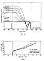
- die Lamellendehnung am Lamellenende bei verschiedenen Kraftstufen und in Trägermitte bei der Versuchsanordnung gemäss Fig. 5,
- Fig. 10a und 10b
- die Dehnung am Lamellenende bei verschiedenen Kraftstufen und in der Trägermitte bei der Versuchsanordnung gemäss Fig. 6,
- Fig. 11a und 11b
- die Dehnung am Lamellenende bei verschiedenen Kraftstufen und in der Trägermitte bei der erfindungsgemässen Versuchsanordnung gemäss Fig. 7,
- Fig. 12a und 12b
- im Längsschnitt und in Draufsicht schematisch dargestellt eine Methode um ein Lamellenende erfindungsgemäss zu verankern,
- Fig. 13a und 13b
- im Längsschnitt und in Draufsicht das Anordnen eines Endverankerungskeils auf einem erfindungsgemäss verankerten Lamellenende,
- Fig. 14a und 14b
- anhand einer Voute im Längsschnitt die Problematik des Anordnens einer Verstärkungslamelle und die entsprechende erfindungsgemässe Lösung, und
- Fig. 15
- eine weitere Bauwerksanordnung, welche vorzugsweise mit einer Verstärkungslamelle erfindungsgemäss verankert, verstärkt wird.
- Fig. 1
- schematically shown in longitudinal section a concrete bridge reinforced by means of a reinforcement lamella,
- Fig. 2
- a side view of a masonry reinforced by reinforcement slats or a push wall, for example suitable for a seismic area,
- Fig. 3
- schematically shown in longitudinal section, the arrangement and anchoring of a slat end according to the invention running into the masonry or building,
- 4a and 4b
- schematically represented in longitudinal and cross-section a concrete beam or a test arrangement, by means of which the terminal anchoring according to the invention is compared with a conventionally anchored slat end,
- 5a and 5b
- 4 is a top view of an experimental arrangement with the concrete support from FIG. 4 with a conventionally glued-on reinforcement lamella,
- 6a and 6b
- an experimental arrangement similar to that in FIGS. 4 and 5, but with an extended slat end,
- 7a, 7b and 7c
- again the same experimental arrangement as in FIGS. 4 to 6, but anchored with a slat end, as suggested according to the invention, running into the concrete beam,
- Fig. 8
- in diagram form the deflection in the three test arrangements according to FIGS. 5, 6 and 7,
- 9a and 9b
- the slat expansion at the slat end at different force levels and in the center of the beam in the test arrangement according to FIG. 5,
- 10a and 10b
- the elongation at the end of the lamella at various force levels and in the center of the beam in the test arrangement according to FIG. 6,
- 11a and 11b
- the elongation at the slat end at different force levels and in the center of the beam in the experimental arrangement according to the invention according to FIG. 7,
- 12a and 12b
- schematically represented in longitudinal section and in plan view a method for anchoring a slat end according to the invention,
- 13a and 13b
- in longitudinal section and in plan view the arrangement of an end anchoring wedge on a slat end anchored according to the invention,
- 14a and 14b
- on the basis of a haunch in longitudinal section, the problem of arranging a reinforcing lamella and the corresponding solution according to the invention, and
- Fig. 15
- a further structure arrangement, which is preferably anchored according to the invention with a reinforcement lamella.
In Fig. 1 ist schematisch im Längsschnitt eine Stahlbetonbrücke
1 dargestellt, umfassend eine Betonplatte 3, welche
durch zwei Pfeiler 5 an den jeweiligen Auflagern 7 aufgestützt
bzw. gehalten ist. Infolge Alterung ist diese Betonbrücke
mittels einer zwischen den beiden Auflagern 7 angeordneten
Verstärkungslamelle 10 verstärkt worden. Die Verstärkungslamelle
10 erstreckt sich zwischen den beiden Auflagern
7 und ist in ihrer ganzen Länge, beispielsweise mit einem
Epoxidharzkleber aufgeklebt, wobei auch endständig im Bereich
A' die Lamelle, wie herkömmlich üblich, an der Betonplatte 3
angeklebt ist. Dabei ist es möglich, wie in der W093/20296
vorgeschlagen, mittels zusätzlicher Gurten oder Stahlplatten
die Lamellenenden zusätzlich zu verankern, bzw. gegen die
Betonplatte 3 zu pressen.In Fig. 1 is a reinforced concrete bridge schematically in
In Fig. 2 ist eine Schubwand 11 eines Gebäudes dargestellt,
das in einem seismisch gefährdeten Gebiet steht. Dabei ist
das Mauerwerk 13 mit seitlich aufgeklebten Verstärkungslamellen
20 verstärkt, wobei die Lamellen üblicherweise endständig
in den unterhalb und oberhalb der Schubwand 13 angeordneten
Betonplatten bzw. der Boden- und Deckenplatte 15 bzw. 17 verankert
ist. Dabei wird, beispielsweise im Bereich A" das Lamellenende
bis in die Betonplatte 17 hineinverlaufend geführt,
um in dieser verankert zu werden. Das Erzeugen dieser
Verankerung ist aufwendig und erfordert einen grossen Arbeitsaufwand.2 shows a
In Fig. 3 ist nun erfindungsgemäss dargestellt, wie in den
Bereichen A' bzw. A" die Lamellenenden einfacher und wirkungsvoller
verankert werden können. Damit wird ermöglicht,
dass im Bereich A' das Lamellenende nicht bis nahe an das
Auflager 7 zu verlaufen hat und im Bereich A" es nicht zwingend
notwendig ist, dass das Lamellenende bis in die Betonplatte
17 zu verlaufen hat. Wie aus Fig. 3 deutlich erkennbar,
verläuft das Lamellenende 22 der Verstärkungslamelle 10
bzw. 20 in die Betonplatte 3 bzw. das Mauerwerk 13 hinein,
und ist entsprechend in diesem Bereich durch Beton bzw. Zementmörtel
überdeckt. Selbstverständlich ist es möglich, die
Ueberdeckung 23 auch mittels eines Polymerklebers, wie beispielsweise
eines Epoxidharz-Mörtels oder einer Polyuretan-
oder Silikonformulierung auszuführen. Die optimale Wahl des
zu verwendenden Materials ist abhängig, beispielsweise vom
Werkstoff, aus welchem die Verstärkungslamelle gefertigt ist.3 is now shown according to the invention, as in the
A 'or A "areas make the slat ends easier and more effective
can be anchored. This enables
that in area A 'the slat end is not close to the
Anhand der nachfolgenden Figuren soll nun gezeigt werden, dass durch das in Fig. 3 schematisch dargestellte Einführen des Lamellenendes in das Bauwerk bzw. in das Mauerwerk hinein eine entscheidende Schubverstärkung am Bauwerk erreicht werden kann, auch wenn die Lamellenlänge nicht wie üblich gefordert von Auflager zu Auflager bzw. von Betonplatte zu Betonplatte gewählt wird. Insbesondere soll mit der nachfolgend beschriebenen Versuchsanordnung gezeigt werden, dass bei gleicher Lamellenlänge eine Erhöhung der Verstärkung erzielt werden kann, wenn das oder die Lamellenende(-n) in das Bauwerk bzw. Bauwerkteil oder Mauerwerk hineinverlaufend verankert (wird) werden.The following figures will now be used to show that by the insertion shown schematically in Fig. 3 of the slat end into the building or into the masonry a decisive shear reinforcement can be achieved on the structure can, even if the slat length is not required as usual from support to support or from concrete slab to concrete slab is chosen. In particular, with the following experimental arrangement described are shown that at the same slat length achieved an increase in gain can be if the or the slat end (s) in the structure or anchored part of the building or masonry (will be.
In Fig. 4a ist im Längsschnitt ein Betonträger 3 analog demjenigen
von Fig. 1 dargestellt, welcher für die nachfolgenden
Versuchsanordnungen verwendet wird. Dabei liegt Betonträger 3
auf den Auflagern 7 auf und umfasst eine Stahlbewehrung 4.
Zusätzlich ist der Betonträger 3 an seiner unteren Seite 8
mittels einer CFK Lamelle 10 verstärkt worden, wobei das eine
Ende 11 der Lamelle praktisch bis zum entsprechenden Auflager
7' hin verläuft, währenddem das gegenüberliegende Lamellenende
13 vom anderen Auflagen 7" beabstandet ist. Fig. 4b
zeigt den Betonträger aus Fig. 4a im Querschnitt.In Fig. 4a, a
An den in den Fig. 4a und 4b schematisch dargestellten
Betonträgern werden nun anhand von verschiedenen Versuchsanordnungen
Biegeversuche durchgeführt, wobei an den beiden je
mit einem Pfeil angedeuteten Stellen 15 eine Kraft F eingeleitet
wird.On the schematically shown in Figs. 4a and 4b
Concrete girders are now based on various test arrangements
Bending tests carried out, each of the two
A force F is introduced with
Die Versuchsanordnung, dargestellt in Fig. 5a, zeigt die Verstärkungslamelle
in Untendraufsicht auf den zu verstärkenden
Betonträger 3, wobei das eine Lamellenende 11 sich bis zum
Auflager 7' hin erstreckt, währenddem das gegenüberliegende
Lamellenende 13' sich um eine Distanz über den entsprechenden
Krafteinleitungspunkt 15" hinaus erstreckt. Die Bemassung der
Versuchsanordnung ist in der Darstellung von Fig. 5a dargestellt,
wobei sich das Lamellenende 13' entsprechend um 20cm
über den Krafteinleitungspunkt 15" hinaus erstreckt. In Fig.
5b sind schematisch die Messpunkte 29 dargestellt, welche am
Lamellenende 13' zum Ermitteln der auftretenden Kräfte bzw.
der auftretenden Dehnung vorgesehen sind. Stelle 24 in Fig.
5a markiert die Mitte des Betonträgers 3, wo ebenfalls eine
Messstelle angeordnet ist.The experimental arrangement, shown in Fig. 5a, shows the reinforcing lamella
in top view of the one to be reinforced
Um ein Versagen der Lamelle 10 im Bereich des Endes 11 zu
verhindern ist weiter eine nicht dargestellte Anpressplatte
vorgesehen. Das Lamellenende 13' ist in herkömmlicher Art und
weise auf die Unterseite des Betonträgers aufgeklebt verankert.To prevent the
Fig. 6a und 6b zeigen eine analoge Versuchsanordnung, wobei
jedoch das Lamellenende 13" sich um 30cm über den entsprechenden
Krafteinleitungspunkt 15" hinaus erstreckt, und somit
näher an das entsprechende Auflager 7" hin reicht. Wiederum
sind im Bereich des Endes 13" mehrere Messstellen vorgesehen,
wie auch mittig an der Stelle 24 am Betonträger 3.6a and 6b show an analog test arrangement, wherein
however, the
In Fig. 7 ist eine Versuchsanordnung dargestellt, wobei nun
das Lamellenende 13'" in das Bauwerkteil hineinverlaufend
verankert ist, was in der Längsschnittsdarstellung von Fig.
7c schematisch dargestellt ist. Dabei erstreckt sich das Lamellenende
13'" wiederum nur um 20cm über den entsprechenden
Krafteinleitungspunkt 15" hinaus, ist also um 10cm mehr beabstandet
vom entsprechenden Auflager 7", verglichen mit der
Versuchsanordnung gemäss Fig. 6a und 6b. Die Verankerung des
Lamellenendes 13'" verläuft entlang einer Strecke von 10cm,
wobei in Fig. 7c das stetig gebogene, in den Betonträger 3
verlaufende Endstück 13a'" im Längsschnitt schematisch dargestellt
ist. Ueber der Lamelle im Bereich 23 wurde in der
Verankerungszone des Endabschnittes 13a'" ein Epoxidharzmörtel
aufgetragen. Wiederum in Fig. 7b sind schematisch mehrere
Messstellen 29 dargestellt, welche auf der Lamelle 10 angeordnet
worden sind. Ebenfalls an der Stelle 24 in der Mitte
des Betonträgers 3 wurde eine Messstelle auf der verstärkungslamelle
10 angeordnet.7 shows an experimental arrangement, where now
the slat end 13 '"running into the building part
is anchored, which in the longitudinal sectional view of Fig.
7c is shown schematically. The slat end extends
13 '"again only 20cm above the corresponding one
Fig. 8 zeigt nun in Diagrammform die Durchbiegung der Versuchsträger
gemessen in Trägermitte mit den drei gemäss den
Fig. 5, 6 und 7 verwendeten Versuchsanordnungen. Die Durchbiegung
δ (mm) ist in Abhängigkeit der an den Stellen 15 eingeleiteten
Kraft (KN) dargestellt, wobei sie durch Biegung
getrennt für die drei Versuchsanordnungen dargestellt ist.Fig. 8 now shows in diagram form the deflection of the test vehicle
measured in the middle of the beam with the three according to the
5, 6 and 7 used experimental arrangements. The deflection
δ (mm) is dependent on the one introduced at
In den Fig. 9, 10 und 11 sind jeweils in den entsprechenden Fig. a die Lamellendehnungen am Lamellenende bei verschiedenen Kraftstufen für die drei Versuchsanordnungen von Fig. 5, 6 und 7 dargestellt, sowie in den jeweiligen Fig. b die Dehnungen in der Trägermitte.9, 10 and 11 are each in the corresponding Fig. A the slat expansions at the slat end at different Force levels for the three test arrangements from FIG. 5, 6 and 7, as well as the strains in the respective FIG in the middle of the beam.
In der nachfolgenden Tabelle 1 sind für die drei Versuchsanordnungen
die gemessenen Tragwiderstände, die mittlere Lamellenspannung
in Trägermitte, sowie die Versagensart der Träger
aufgeführt.
Diskussion der Resultate bzw. der Diagramme gemäss den Fig. 8 bis 11 sowie von Tabelle 1:Discussion of the results or the diagrams according to FIG. 8 to 11 and from Table 1:
Die maximale Last und insbesondere die maximale Lamellendehnung
in der erfindungsgemässen Versuchsanordnung gemäss Fig.
7 konnten gegenüber den Trägern der Versuchsanordnungen 5 und
6 wesentlich gesteigert werden. Die Träger gemäss Fig. 5 und
6 zeigen trotz unterschiedlichen Verankerungslängen im Bereich
der Enden 13' und 13" ein ähnliches Verhalten. Im mittleren
Trägerbereich werden etwa dieselben Dehnungen registriert.
Jeweils beim Erreichen der Fliesslast scheren die
Lamellen vom Lamellenende her ab.The maximum load and in particular the maximum slat expansion
in the experimental arrangement according to the invention according to FIG.
7 compared to the carriers of the
Die Lamelle des Trägers gemäss der erfindungsgemäss vorgeschlagenen Anordnung in Fig. 7 ist am einen Ende 13'" im Betonträger 3 eingelassen und mit Klebstoff 23 zugedeckt. Die maximalen Lamellendehnungen konnten gegenüber den oben beschriebenen Versuchen, im Zusammenhang mit den Anordnungen gemäss den Fig. 5 und 6, deutlich gesteigert werden. Dieses Verhalten kann vermutlicherweise wie folgt begründet werden:
- Umlenkung der resultierenden Spannungskomponenten senkrecht
zur geklebten Lamelle. Damit wird die Lamelle angepresst,
womit im Beton Druckspannungen entstehen. Bei einer entsprechend
idealen und optimierten Geometrie des in
den Träger 3 hineinverlaufenden Endabschnittes 13a'" kann eine Anpressung der Lamelle an den Träger erzielt werden, die mit der Wirkung der in der internationalen PCT-Anmeldung WO 93/20296 beschriebenen Querspannung vergleichbar ist. - Der Klebstoff auf der Lamelle oder ein Anpresskeil gemäss Fig. 3 oder der nachfolgenden Fig. 13a und b verhindert das frühzeitige Ablösen des Lamellenendes, das durch die senkrechte Spannungskomponente, die vom Träger weggerichtet ist, hervorgerufen wird.
- Deflection of the resulting tension components perpendicular to the glued lamella. This presses on the lamella, creating compressive stress in the concrete. With a correspondingly ideal and optimized geometry of the
end section 13a ′ ″ running into thecarrier 3, the lamella can be pressed against the carrier, which is comparable to the effect of the transverse stress described in the international PCT application WO 93/20296. - The adhesive on the lamella or a pressure wedge according to FIG. 3 or the following FIGS. 13a and b prevents premature detachment of the lamella end, which is caused by the vertical tension component, which is directed away from the carrier.
Mittels der Versuchsanordnungen in den Fig. 5 bis 7 kann somit eindrücklich dargestellt werden, dass durch das erfindungsgemässe endständige, in das Bauwerk hineinverlaufende Verankern der Verstärkungslamelle eine wesentlich erhöhte Verstärkung am Bauwerk erzielt werden, verglichen mit einer gleich langen oder längeren Verstärkungslamelle, deren entsprechendes Ende nicht erfindungsgemäss in das Bauwerk hineinverlaufend verankert ist, sondern wie aus dem Stand der Technik bekannt, entlang einer wesentlich längeren Verankerungsstrecke auf das Bauwerk aufgeklebt bzw. an diesem anliegend verankert ist.By means of the experimental arrangements in FIGS. 5 to 7 it is possible are impressively shown that by the inventive terminal, running into the building Anchoring the reinforcement lamella a significantly increased Reinforcement can be achieved on the structure compared to a reinforcing lamella of the same length or longer, their corresponding Not running into the building according to the invention is anchored, but as from the state of the Known technology, along a much longer anchoring route glued to or attached to the structure is anchored.
In den Fig. 12a und 12b ist ein Verfahren schematisch dargestellt,
wie das erfindungsgemässe, endständige Verankern einer
Verstärkungslamelle 10 auf relativ einfache Art und weise
möglich ist. In der Regel ist ein Einschleifen, Einfräsen
oder Abschleifen in das Bauwerk hinein nicht möglich, so dass
nun, wie in den Fig. 12a und 12b dargestellt, vorgeschlagen
wird, das endständige in das Bauwerk-Hineinverlaufen des Verstärkungslamellenendes
22 mittels sogenannter abgestufter
Kernbohrungen zu bewerkstelligen. So werden im endständigen
Bereich sogenannte Kernbohrungen 31 mittels beispielsweise
einer herkömmlichen Bohrmaschine in den zu verstärkenden Beton
3 abgestuft hineingetrieben, wobei die erste Bohrung
entfernt vom Lamellenende nur eine geringe Tiefe aufweist,
währenddem die letzte Kernbohrung 31 im Bereich des Lamellenendes
eine grosse Tiefe aufweist. Derartige Kernbohrungen
können beispielsweise einen Lochdurchmesser von 10 oder mehr
cm aufweisen, je nach dem, wie breit die zu verankernde Verstärkungslamelle
10 ist. Nach dem in das Bauwerk hineinverlaufende
Anordnen des Lamellenendes 22 kann erneut, wie bereits
in Fig. 3 dargestellt, ein Verankerungskeil 23 angeordnet
werden.12a and 12b, a method is shown schematically,
such as the terminal anchoring according to the
Ein derartiger Verankerungskeil ist ebenfalls in den Fig. 13a
und 13b dargestellt, wobei nun zusätzlich Befestigungsmittel
33 angeordnet sind, wobei es sich beispielsweise um Schrauben,
Bolzen, Schlaufen, etc. handeln kann. Mittels dieser
Befestigungsmittel 33 wird die Verankerungswirkung des Keils
23 auf das Lamellenende 22 zusätzlich verstärkt. Dabei zeigt
Fig. 13a den Keil 23 im Längsschnitt, währenddem Fig. 13b
eine Draufsicht auf den Keil 23 darstellt.Such an anchoring wedge is also shown in Fig. 13a
and 13b, with additional fastening means now
33 are arranged, for example screws,
Bolts, loops, etc. can act. By means of this
Fastening means 33 becomes the anchoring effect of the
In den Fig. 14a und 14b ist eine Betonkonstruktion 32 dargestellt,
wie beispielsweise eine Tragkonstruktion bei Galerien
oder Einstellhallen, bei welcher Konstruktion die Deckenplatte
35 und die Seitenwandung 37 über eine sogenannte Voute 39
im Eckbereich miteinander verbunden sind. Falls nun die Unterseite
der Decke 35 mittels einer Verstärkungslamelle 10 zu
verstärken ist, zeigt sich in Fig. 14a deutlich, dass ein
Verankern des Lamellenendes 13 im Bereich der Voute ungünstig
ist, da beim Auftreten von Zugkräften auf die verstärkungslamelle
10 diese im Eckbereich 36 abgelöst wird. 14a and 14b, a
Aus diesem Grunde wird, wie in Fig. 14b dargestellt, erfindungsgemäss
vorgeschlagen, die Verstärkungslamelle 34 bzw.
deren Ende 22 im Eckbereich 36 in die Betondecke 35 hineinverlaufend
zu verankern. Beim Belasten der Betondecke 35 wird
die infolge des Biegemoments resultierende Zugspannungskomponente
auf die Lamelle im Endbereich der Lamelle in die Decke
hinein umgelenkt, womit das Lamellenende 22 nicht abgelöst
wird.For this reason, according to the invention, as shown in FIG. 14b
proposed the
Fig. 15 schlussendlich zeigt eine weitere Bauwerksanordnung,
beispielsweise erneut eine Tragkonstruktion, umfassend eine
Betondecke 41 sowie eine Trennwand oder einen Längspfeiler
43, wobei erneut die Decke 41 mittels einer Verstärkungslamelle
10 verstärkt ist. Im Eckbereich 45, zwischen Decke 41
und Pfeiler 43, ist erfindungsgemäss das Lamellenende 22 in
die Decke hinein verlaufend verankert.15 finally shows a further structure arrangement,
for example again a supporting structure, comprising one
Anhand der in Fig. 15 eingezeichneten Hilfslinie 53 wird der
Verlauf des Biegemoments in bezug auf das Bauwerkteil bzw.
auf die durch die Decke verlaufende Systemmittelebene 47 dargestellt.
Dabei zeigt sich deutlich das Durchlaufen eines
Nullpunktes im Abstand x vom Pfeiler 43 nahe im Eckbereich 45
und eine anschliessende starke Zunahme. Durch das erfindungsgemässe
Verankern des Lamellenendes 22 im Abstandsbereich x,
wo keine Zugkraft auftritt, ist es möglich bereits beginnend
vom Nullpunkt die anschliessend entstehende Zugspannung durch
die Verstärkungslamelle 10 voll aufzufangen. Im Falle, dass
die Verstärkungslamelle 10, wie herkömmlich aufgeklebt, im
Eckbereich 45 verankert wäre, wäre ein Auffangen der entstehenden
Zugspannung erst in einem Abstand grösser x vom Eckbereich
45 möglich, womit die Gefahr des Abscherens der Lamelle
10 von der Betondecke 41 gegeben ist. The
Die Fig. 1 bis 15 dienen lediglich der näheren Erläuterung und Veranschaulichung der Erfindung und eine erfindungsgemäss vorgeschlagene, endständige Verankerung von Verstärkungslamellen kann selbstverständlich auf x-beliebige Art und Weise im Rahmen der Ausprüche gewählt werden. Auch der für die Verstärkungslamellen verwendete werkstoff kann x-beliebig sein, so kann eine Lamelle aus Eisenblech, Stahl, Aluminium, einem verstärkten Polymer, wie insbesondere GFK verstärktem Epoxidharz, usw. bestehen. Erfindungsgemäß ist eine an einem Bauwerk oder Mauerwerk auf- oder angebrachte Verstärkungslamelle wenigstens mit einem Ende in das Bauwerk bzw. Mauerwerk hineinverlaufend verankert, ob dabei ein Verstärkungskeil verwendet wird oder nicht richtet sich nach den Anforderungen und den Oertlichkeiten.1 to 15 serve only for a more detailed explanation and illustration of the invention and a terminal anchoring proposed according to the invention of reinforcing lamellas can of course be applied to any Way can be chosen in the context of the sayings. Also for the reinforcement slats the material used can be any, so can be a sheet of iron, steel, aluminum, a reinforced polymer, such as in particular fiberglass reinforced epoxy resin, etc. exist. According to the invention one attached to or attached to a building or masonry Reinforcement lamella at least with one end in it Anchored structure or masonry running in whether a reinforcement wedge is used or not depends on the requirements and the locations.
Claims (11)
- An arrangement for reinforcing an elongate and/or planar structure (3) or structural element or a wall (13) by means of at least one lamellar reinforcement (10, 20) arranged loosely or under pretension on the structure, structural element or wall, characterised in that the lamella, of which there is at least one and which serves as the reinforcement, is anchored at at least one end (13'", 23) by extending into the structure, structural element or wall.
- An arrangement according to claim 1, characterised in that the lamella end is anchored by extending into the structure in curved-round manner.
- An arrangement according to either one of claims 1 or 2, characterised in that at least one end of the lamella, of which there is at least one, for reinforcing the structure, structural element or wall is embedded in the structure or wall by extending at as far as possible a constant curve, the embedded end being covered by means of concrete, cement, mortar and/or a polymer-reinforced material, such as in particular an adhesive.
- An arrangement according to any one of claims 1 to 3, characterised in that the reinforcing lamella, of which there is at least one, is made of a metallic material, such as in particular iron, steel or aluminium, or a reinforced plastics material, such as in particular a polymer reinforced with glass fibres, carbon fibres, aramide fibres etc.
- An arrangement according to any one of claims 1 to 4, characterised in that the lamella end extending into the structure or structural element or wall is additionally pressed against the structure or wall with a wedge-, plate-or belt-type or lamellar element.
- An arrangement according to any one of claims 1 to 5, characterised in that the lamella end is additionally anchored in the structure or wall by means of mechanical fastening means, such as in particular screws, rivets, pegs and the like.
- A structural element provided for supporting purposes, reinforced with an arrangement according to any one of claims 1 to 6.
- A wall with an arrangement according to any one of claims 1 to 6.
- A method of reinforcing an elongate and/or planar structure, structural element or wall by means of at least one lamellar reinforcement arranged loosely or under pretension on the structure or wall, characterised in that at least one of the lamella ends is arranged so as to extend into the structure or structural element or wall in curved manner.
- A method according to claim 9, characterised in that the lamella end extending into the structure or wall is covered by means of concrete, cement mortar and/or a reinforced polymer, such as polymer concrete or an adhesive material.
- A method according to claim 9, characterised in that the curved lamella end is pressed or driven against the structure or wall by means of a wedge, by means of a plate or by means of lamellar or belt-type elements.
Applications Claiming Priority (3)
| Application Number | Priority Date | Filing Date | Title |
|---|---|---|---|
| CH45/95 | 1995-01-09 | ||
| CH4595 | 1995-01-09 | ||
| PCT/CH1995/000298 WO1996021785A1 (en) | 1995-01-09 | 1995-12-12 | Securing of reinforcing strips |
Publications (2)
| Publication Number | Publication Date |
|---|---|
| EP0803020A1 EP0803020A1 (en) | 1997-10-29 |
| EP0803020B1 true EP0803020B1 (en) | 1998-09-16 |
Family
ID=4178079
Family Applications (1)
| Application Number | Title | Priority Date | Filing Date |
|---|---|---|---|
| EP95938340A Expired - Lifetime EP0803020B1 (en) | 1995-01-09 | 1995-12-12 | Securing of reinforcing strips |
Country Status (9)
| Country | Link |
|---|---|
| US (1) | US5937606A (en) |
| EP (1) | EP0803020B1 (en) |
| JP (1) | JPH10512635A (en) |
| AT (1) | ATE171240T1 (en) |
| AU (1) | AU3977195A (en) |
| DE (1) | DE59503647D1 (en) |
| DK (1) | DK0803020T3 (en) |
| ES (1) | ES2122696T3 (en) |
| WO (1) | WO1996021785A1 (en) |
Families Citing this family (27)
| Publication number | Priority date | Publication date | Assignee | Title |
|---|---|---|---|---|
| ATE202614T1 (en) | 1997-01-23 | 2001-07-15 | Sika Ag | FLAT RIBBON LAMB FOR REINFORCEMENT OF COMPONENTS AND METHOD FOR THE PRODUCTION THEREOF |
| DE19702246A1 (en) | 1997-01-23 | 1998-07-30 | Sika Ag | Ribbon slats and their use to reinforce structural parts |
| DE19730174C2 (en) * | 1997-07-15 | 2001-12-06 | Bilfinger Berger Bau | Component |
| DE19733067A1 (en) * | 1997-07-31 | 1999-02-04 | Sika Ag | Ribbon slat for reinforcing components and method for attaching the ribbon slat to a component |
| DE19733066A1 (en) * | 1997-07-31 | 1999-02-04 | Sika Ag | Method for fastening a flat strip lamella to a component surface |
| AU740242B2 (en) * | 1997-08-26 | 2001-11-01 | Sika Technology Ag | Reinforcement device for supporting structures |
| KR100408437B1 (en) * | 1997-09-16 | 2003-12-06 | 신닛뽄세이테쯔 카부시키카이샤 | Structure for reinforcing concrete member and reinforcing method |
| DE19742210A1 (en) * | 1997-09-24 | 1999-03-25 | Goehler Bernhard Dipl Ing | Concrete-strengthening and repairing system |
| FR2771765A1 (en) * | 1997-11-28 | 1999-06-04 | Jean Claude Galland | THICK MASONRY BUILDING DEVICES |
| DE19753318A1 (en) * | 1997-12-02 | 1999-06-10 | Sika Ag | Reinforcing element for load-bearing or load-transmitting components and method for fastening it to a component surface |
| US6464811B1 (en) * | 1998-02-26 | 2002-10-15 | Eidgenössiche Materialprüfungs-und Forschungsanstalt EMPA | Method and device for applying pretensed tension-proof reinforcing strips to a construction |
| EP1013851A1 (en) * | 1998-12-14 | 2000-06-28 | Top Glass S.p.A. | Process for manufacturing a structural reinforcing element for building constructions and structural reinforcing element so obtained |
| DE19904185A1 (en) * | 1999-02-02 | 2000-08-03 | Sika Ag, Vormals Kaspar Winkler & Co | Process for the production of a flat tape |
| FR2790500B1 (en) * | 1999-03-01 | 2002-06-07 | Freyssinet Int Stup | METHOD AND DEVICE FOR REINFORCING A CONCRETE STRUCTURE |
| US7770354B2 (en) * | 2002-08-29 | 2010-08-10 | Bui Thuan H | Lightweight modular cementitious panel/tile for use in construction |
| DE10249266B3 (en) * | 2002-10-23 | 2004-04-08 | Leonhardt, Andrä und Partner Beratende Ingenieure VBI GmbH | Tension device for belt-like traction members on concrete support structures has guide member locally fixed between tension bar and tension anchor and supporting traction member for sliding movement upwards |
| EP1507052A1 (en) | 2003-08-13 | 2005-02-16 | Sika Technology AG | Force transfer element |
| EP1507050A1 (en) | 2003-08-13 | 2005-02-16 | Sika Technology AG | Force transfer element |
| US20080277264A1 (en) * | 2007-05-10 | 2008-11-13 | Fluid-Quip, Inc. | Alcohol production using hydraulic cavitation |
| FR2948712B1 (en) * | 2009-08-03 | 2015-03-06 | Soletanche Freyssinet | METHOD FOR STRENGTHENING A CONSTRUCTION STRUCTURE AND STRENGTHENING THE STRENGTH |
| BR112015030524A2 (en) * | 2013-06-06 | 2017-07-25 | Sika Tech Ag | arrangement and method for reinforcement of supporting structures |
| WO2016005941A1 (en) | 2014-07-09 | 2016-01-14 | Faculdade De Ciências E Tecnologia Da Universidade Nova De Lisboa | Structural strengthening system with internally anchored reinforcements by adherence |
| US9784004B2 (en) * | 2014-08-19 | 2017-10-10 | Kulstoff Composite Products, LLC | Fiber reinforced anchors and connectors, methods of making anchors and connectors, and processes for reinforcing a structure |
| US11236508B2 (en) * | 2018-12-12 | 2022-02-01 | Structural Technologies Ip, Llc | Fiber reinforced composite cord for repair of concrete end members |
| US12497793B2 (en) | 2020-10-21 | 2025-12-16 | Kulstoff Composite Products, LLC | Fiber-reinforced polymer anchors and connectors for repair and strengthening of structures configured for field testing, and assemblies for field testing the same |
| EP4124703B1 (en) * | 2021-07-27 | 2024-10-23 | Sika Technology AG | Reinforced steel-concrete structure |
| CN113515802B (en) * | 2021-09-14 | 2021-12-07 | 四川交达预应力工程检测科技有限公司 | Machine learning-based anchor critical value detection method and system and storage medium |
Family Cites Families (12)
| Publication number | Priority date | Publication date | Assignee | Title |
|---|---|---|---|---|
| DE1434075A1 (en) * | 1961-05-26 | 1968-10-31 | Ney Gyl Labor Kg | Process for the subsequent or additional reinforcement of components made of concrete |
| DE1684293A1 (en) * | 1966-03-08 | 1969-10-30 | Inst Stahlbeton | Securing structure for load-bearing reinforced concrete and prestressed concrete structures |
| US3900102A (en) * | 1970-01-14 | 1975-08-19 | Grace W R & Co | Waterproofing means and method |
| DE2510262A1 (en) * | 1975-03-08 | 1976-09-09 | Hans Binker | Strength improvement for timber beams - uses fibre bundles and webbing embedded in grooves along longitudinal faces |
| US4396665A (en) * | 1980-06-16 | 1983-08-02 | W. R. Grace & Co. | Self-adhesive roofing laminates having metal layer therein |
| US4534924A (en) * | 1983-09-19 | 1985-08-13 | Novi Development Corporation | Method for molding concrete slabs and battery mold therefor |
| US5055330A (en) * | 1986-09-08 | 1991-10-08 | Owens-Corning Fiberglas Corporation | Edge-reinforced folded glass wool insulation layers |
| US5197245A (en) * | 1990-08-13 | 1993-03-30 | Vsl Corporation | Structural wall reinforcement apparatus and method |
| US5542563A (en) * | 1991-07-15 | 1996-08-06 | Matias; Carlos J. D. | Modified flexible insert for a generally rectangular container |
| DE4213839C2 (en) * | 1992-04-29 | 2001-04-26 | Hilti Ag | Reinforcement of masonry components |
| US5398472A (en) * | 1993-02-19 | 1995-03-21 | The Shandel Group | Fiber-bale composite structural system and method |
| US5566509A (en) * | 1993-10-21 | 1996-10-22 | Long; Larry L. | Door jamb reinforcement strip |
-
1995
- 1995-12-12 US US08/860,596 patent/US5937606A/en not_active Expired - Fee Related
- 1995-12-12 DE DE59503647T patent/DE59503647D1/en not_active Expired - Fee Related
- 1995-12-12 ES ES95938340T patent/ES2122696T3/en not_active Expired - Lifetime
- 1995-12-12 EP EP95938340A patent/EP0803020B1/en not_active Expired - Lifetime
- 1995-12-12 AT AT95938340T patent/ATE171240T1/en not_active IP Right Cessation
- 1995-12-12 WO PCT/CH1995/000298 patent/WO1996021785A1/en not_active Ceased
- 1995-12-12 AU AU39771/95A patent/AU3977195A/en not_active Abandoned
- 1995-12-12 DK DK95938340T patent/DK0803020T3/en active
- 1995-12-12 JP JP8521346A patent/JPH10512635A/en not_active Ceased
Also Published As
| Publication number | Publication date |
|---|---|
| DE59503647D1 (en) | 1998-10-22 |
| WO1996021785A1 (en) | 1996-07-18 |
| AU3977195A (en) | 1996-07-31 |
| JPH10512635A (en) | 1998-12-02 |
| US5937606A (en) | 1999-08-17 |
| EP0803020A1 (en) | 1997-10-29 |
| ES2122696T3 (en) | 1998-12-16 |
| ATE171240T1 (en) | 1998-10-15 |
| DK0803020T3 (en) | 1999-06-14 |
Similar Documents
| Publication | Publication Date | Title |
|---|---|---|
| EP0803020A1 (en) | Securing of reinforcing strips | |
| EP1007809B1 (en) | Reinforcement device for supporting structures | |
| EP2997197B1 (en) | Method for pre-stressing a steel structure, and steel structure pre-stressed using said method | |
| EP0040815B1 (en) | Site-assembled composite beam | |
| EP3303707B1 (en) | Method for producing a roadway plate for a bridge | |
| EP2143843A2 (en) | Steel-concrete composite trough as bridgedeck and method for its production | |
| DE2025471A1 (en) | Concrete structure made from prefabricated components | |
| AT526252B1 (en) | METHOD FOR PRODUCING A ROAD Slab FOR A BRIDGE | |
| DE69518396T2 (en) | Wood-concrete composite construction, especially for the production of bridge ceilings | |
| DE60007842T2 (en) | PANEL, ASSEMBLING SUCH PANELS AND USE TO TAKE HEAVY LOADS | |
| DE2929350A1 (en) | Composite beams for building ceilings | |
| DE3021672A1 (en) | VICE AMOUNT | |
| DE29609800U1 (en) | Ceiling construction and ceiling element | |
| DE202006015693U1 (en) | Wood-concrete connecting unit for use in building construction, has slab and support units connected with each other by connection unit that is embedded in slab unit, where slab unit is made of concrete and support unit is made of wood | |
| EP4124703A1 (en) | Reinforced steel-concrete structure | |
| EP1645693A1 (en) | Connecting system for cantilevering constructions of buildings | |
| EP3591130B1 (en) | Ceiling construction | |
| WO1998032934A1 (en) | Flat strip lamella and its use for reinforcing building components | |
| DE10134777B4 (en) | Building and process for its production | |
| EP0826848B1 (en) | Device for the concentrated introduction of forces into concrete | |
| DE102008022180B3 (en) | Frame corner forming arrangement for roller support in concrete construction, has reinforced concrete wall that is reinforced concrete support, and ends of roller support are provided as double-T-profile that is recessed over frame corner | |
| DE2451574C3 (en) | Prestressed concrete deck slab for bridge structures as well as laying equipment and process for their manufacture | |
| AT405955B (en) | Load-bearing element for the production of load-bearing structures, and load-bearing structure produced using such load-bearing elements | |
| DE19825526A1 (en) | Rail member, esp. a prefabricated rail section | |
| DE102016121713A1 (en) | segment bridge |
Legal Events
| Date | Code | Title | Description |
|---|---|---|---|
| PUAI | Public reference made under article 153(3) epc to a published international application that has entered the european phase |
Free format text: ORIGINAL CODE: 0009012 |
|
| 17P | Request for examination filed |
Effective date: 19970703 |
|
| AK | Designated contracting states |
Kind code of ref document: A1 Designated state(s): AT BE CH DE DK ES FR GB GR IE IT LI LU MC NL PT SE |
|
| GRAG | Despatch of communication of intention to grant |
Free format text: ORIGINAL CODE: EPIDOS AGRA |
|
| 17Q | First examination report despatched |
Effective date: 19971107 |
|
| GRAG | Despatch of communication of intention to grant |
Free format text: ORIGINAL CODE: EPIDOS AGRA |
|
| GRAH | Despatch of communication of intention to grant a patent |
Free format text: ORIGINAL CODE: EPIDOS IGRA |
|
| ITF | It: translation for a ep patent filed | ||
| GRAH | Despatch of communication of intention to grant a patent |
Free format text: ORIGINAL CODE: EPIDOS IGRA |
|
| GRAA | (expected) grant |
Free format text: ORIGINAL CODE: 0009210 |
|
| AK | Designated contracting states |
Kind code of ref document: B1 Designated state(s): AT BE CH DE DK ES FR GB GR IE IT LI LU MC NL PT SE |
|
| REF | Corresponds to: |
Ref document number: 171240 Country of ref document: AT Date of ref document: 19981015 Kind code of ref document: T |
|
| REG | Reference to a national code |
Ref country code: CH Ref legal event code: NV Representative=s name: TROESCH SCHEIDEGGER WERNER AG Ref country code: CH Ref legal event code: EP |
|
| GBT | Gb: translation of ep patent filed (gb section 77(6)(a)/1977) |
Effective date: 19980917 |
|
| REF | Corresponds to: |
Ref document number: 59503647 Country of ref document: DE Date of ref document: 19981022 |
|
| REG | Reference to a national code |
Ref country code: IE Ref legal event code: FG4D Free format text: GERMAN |
|
| ET | Fr: translation filed | ||
| REG | Reference to a national code |
Ref country code: ES Ref legal event code: FG2A Ref document number: 2122696 Country of ref document: ES Kind code of ref document: T3 |
|
| REG | Reference to a national code |
Ref country code: PT Ref legal event code: SC4A Free format text: AVAILABILITY OF NATIONAL TRANSLATION Effective date: 19980918 |
|
| REG | Reference to a national code |
Ref country code: DK Ref legal event code: T3 |
|
| PLBE | No opposition filed within time limit |
Free format text: ORIGINAL CODE: 0009261 |
|
| STAA | Information on the status of an ep patent application or granted ep patent |
Free format text: STATUS: NO OPPOSITION FILED WITHIN TIME LIMIT |
|
| 26N | No opposition filed | ||
| REG | Reference to a national code |
Ref country code: GB Ref legal event code: IF02 |
|
| PGFP | Annual fee paid to national office [announced via postgrant information from national office to epo] |
Ref country code: IE Payment date: 20021121 Year of fee payment: 8 |
|
| PGFP | Annual fee paid to national office [announced via postgrant information from national office to epo] |
Ref country code: SE Payment date: 20021122 Year of fee payment: 8 |
|
| PGFP | Annual fee paid to national office [announced via postgrant information from national office to epo] |
Ref country code: PT Payment date: 20021125 Year of fee payment: 8 Ref country code: MC Payment date: 20021125 Year of fee payment: 8 Ref country code: DK Payment date: 20021125 Year of fee payment: 8 |
|
| PGFP | Annual fee paid to national office [announced via postgrant information from national office to epo] |
Ref country code: LU Payment date: 20021129 Year of fee payment: 8 Ref country code: GR Payment date: 20021129 Year of fee payment: 8 Ref country code: ES Payment date: 20021129 Year of fee payment: 8 |
|
| PGFP | Annual fee paid to national office [announced via postgrant information from national office to epo] |
Ref country code: GB Payment date: 20021211 Year of fee payment: 8 |
|
| PGFP | Annual fee paid to national office [announced via postgrant information from national office to epo] |
Ref country code: AT Payment date: 20021217 Year of fee payment: 8 |
|
| PGFP | Annual fee paid to national office [announced via postgrant information from national office to epo] |
Ref country code: FR Payment date: 20021223 Year of fee payment: 8 |
|
| PGFP | Annual fee paid to national office [announced via postgrant information from national office to epo] |
Ref country code: NL Payment date: 20021231 Year of fee payment: 8 |
|
| PGFP | Annual fee paid to national office [announced via postgrant information from national office to epo] |
Ref country code: DE Payment date: 20030115 Year of fee payment: 8 Ref country code: BE Payment date: 20030115 Year of fee payment: 8 |
|
| PGFP | Annual fee paid to national office [announced via postgrant information from national office to epo] |
Ref country code: CH Payment date: 20030227 Year of fee payment: 8 |
|
| PG25 | Lapsed in a contracting state [announced via postgrant information from national office to epo] |
Ref country code: LU Free format text: LAPSE BECAUSE OF NON-PAYMENT OF DUE FEES Effective date: 20031212 Ref country code: IE Free format text: LAPSE BECAUSE OF NON-PAYMENT OF DUE FEES Effective date: 20031212 Ref country code: GB Free format text: LAPSE BECAUSE OF NON-PAYMENT OF DUE FEES Effective date: 20031212 Ref country code: AT Free format text: LAPSE BECAUSE OF NON-PAYMENT OF DUE FEES Effective date: 20031212 |
|
| PG25 | Lapsed in a contracting state [announced via postgrant information from national office to epo] |
Ref country code: SE Free format text: LAPSE BECAUSE OF NON-PAYMENT OF DUE FEES Effective date: 20031213 Ref country code: ES Free format text: LAPSE BECAUSE OF NON-PAYMENT OF DUE FEES Effective date: 20031213 |
|
| PG25 | Lapsed in a contracting state [announced via postgrant information from national office to epo] |
Ref country code: MC Free format text: LAPSE BECAUSE OF NON-PAYMENT OF DUE FEES Effective date: 20031231 Ref country code: LI Free format text: LAPSE BECAUSE OF NON-PAYMENT OF DUE FEES Effective date: 20031231 Ref country code: CH Free format text: LAPSE BECAUSE OF NON-PAYMENT OF DUE FEES Effective date: 20031231 Ref country code: BE Free format text: LAPSE BECAUSE OF NON-PAYMENT OF DUE FEES Effective date: 20031231 |
|
| PG25 | Lapsed in a contracting state [announced via postgrant information from national office to epo] |
Ref country code: DK Free format text: LAPSE BECAUSE OF NON-PAYMENT OF DUE FEES Effective date: 20040102 |
|
| BERE | Be: lapsed |
Owner name: EIDGENOSSISCHE MATERIALPRUFUNGS- UND FORSCHUNGSANS Effective date: 20031231 |
|
| PG25 | Lapsed in a contracting state [announced via postgrant information from national office to epo] |
Ref country code: PT Free format text: LAPSE BECAUSE OF NON-PAYMENT OF DUE FEES Effective date: 20040630 |
|
| PG25 | Lapsed in a contracting state [announced via postgrant information from national office to epo] |
Ref country code: NL Free format text: LAPSE BECAUSE OF NON-PAYMENT OF DUE FEES Effective date: 20040701 Ref country code: DE Free format text: LAPSE BECAUSE OF NON-PAYMENT OF DUE FEES Effective date: 20040701 |
|
| PG25 | Lapsed in a contracting state [announced via postgrant information from national office to epo] |
Ref country code: GR Free format text: LAPSE BECAUSE OF NON-PAYMENT OF DUE FEES Effective date: 20040705 |
|
| EUG | Se: european patent has lapsed | ||
| GBPC | Gb: european patent ceased through non-payment of renewal fee |
Effective date: 20031212 |
|
| REG | Reference to a national code |
Ref country code: CH Ref legal event code: PL |
|
| REG | Reference to a national code |
Ref country code: DK Ref legal event code: EBP |
|
| PG25 | Lapsed in a contracting state [announced via postgrant information from national office to epo] |
Ref country code: FR Free format text: LAPSE BECAUSE OF NON-PAYMENT OF DUE FEES Effective date: 20040831 |
|
| NLV4 | Nl: lapsed or anulled due to non-payment of the annual fee |
Effective date: 20040701 |
|
| REG | Reference to a national code |
Ref country code: IE Ref legal event code: MM4A |
|
| REG | Reference to a national code |
Ref country code: FR Ref legal event code: ST |
|
| REG | Reference to a national code |
Ref country code: PT Ref legal event code: MM4A Free format text: LAPSE DUE TO NON-PAYMENT OF FEES Effective date: 20040630 |
|
| REG | Reference to a national code |
Ref country code: ES Ref legal event code: FD2A Effective date: 20031213 |
|
| PG25 | Lapsed in a contracting state [announced via postgrant information from national office to epo] |
Ref country code: IT Free format text: LAPSE BECAUSE OF NON-PAYMENT OF DUE FEES;WARNING: LAPSES OF ITALIAN PATENTS WITH EFFECTIVE DATE BEFORE 2007 MAY HAVE OCCURRED AT ANY TIME BEFORE 2007. THE CORRECT EFFECTIVE DATE MAY BE DIFFERENT FROM THE ONE RECORDED. Effective date: 20051212 |