EP0803027B1 - Dispositif d'injection de carburant pour moteur a combustion interne - Google Patents
Dispositif d'injection de carburant pour moteur a combustion interne Download PDFInfo
- Publication number
- EP0803027B1 EP0803027B1 EP96931751A EP96931751A EP0803027B1 EP 0803027 B1 EP0803027 B1 EP 0803027B1 EP 96931751 A EP96931751 A EP 96931751A EP 96931751 A EP96931751 A EP 96931751A EP 0803027 B1 EP0803027 B1 EP 0803027B1
- Authority
- EP
- European Patent Office
- Prior art keywords
- fuel
- heating element
- injection device
- valve
- fuel injection
- Prior art date
- Legal status (The legal status is an assumption and is not a legal conclusion. Google has not performed a legal analysis and makes no representation as to the accuracy of the status listed.)
- Expired - Lifetime
Links
- 239000000446 fuel Substances 0.000 title claims description 130
- 239000007924 injection Substances 0.000 title claims description 58
- 238000002347 injection Methods 0.000 title claims description 58
- 238000002485 combustion reaction Methods 0.000 title claims description 23
- 238000010438 heat treatment Methods 0.000 claims description 74
- 239000006200 vaporizer Substances 0.000 claims description 13
- 239000000463 material Substances 0.000 claims description 7
- 239000011148 porous material Substances 0.000 claims description 3
- 229910001111 Fine metal Inorganic materials 0.000 claims description 2
- 239000000919 ceramic Substances 0.000 claims description 2
- 210000002268 wool Anatomy 0.000 claims description 2
- 238000011144 upstream manufacturing Methods 0.000 claims 1
- 239000007921 spray Substances 0.000 description 17
- 239000007789 gas Substances 0.000 description 14
- 239000007788 liquid Substances 0.000 description 9
- 239000000203 mixture Substances 0.000 description 7
- 238000002360 preparation method Methods 0.000 description 5
- 238000001704 evaporation Methods 0.000 description 4
- 230000008020 evaporation Effects 0.000 description 4
- 239000012530 fluid Substances 0.000 description 4
- 238000007789 sealing Methods 0.000 description 4
- 238000000889 atomisation Methods 0.000 description 3
- 230000015572 biosynthetic process Effects 0.000 description 3
- 241000446313 Lamella Species 0.000 description 2
- 230000001771 impaired effect Effects 0.000 description 2
- 230000001133 acceleration Effects 0.000 description 1
- 230000006835 compression Effects 0.000 description 1
- 238000007906 compression Methods 0.000 description 1
- 238000010276 construction Methods 0.000 description 1
- 238000001816 cooling Methods 0.000 description 1
- 230000001419 dependent effect Effects 0.000 description 1
- 238000005485 electric heating Methods 0.000 description 1
- 239000003344 environmental pollutant Substances 0.000 description 1
- 238000009413 insulation Methods 0.000 description 1
- 238000004519 manufacturing process Methods 0.000 description 1
- 230000002093 peripheral effect Effects 0.000 description 1
- 231100000719 pollutant Toxicity 0.000 description 1
- 230000001105 regulatory effect Effects 0.000 description 1
- 230000002269 spontaneous effect Effects 0.000 description 1
- 239000012899 standard injection Substances 0.000 description 1
- 230000036962 time dependent Effects 0.000 description 1
Images

Classifications
-
- F—MECHANICAL ENGINEERING; LIGHTING; HEATING; WEAPONS; BLASTING
- F02—COMBUSTION ENGINES; HOT-GAS OR COMBUSTION-PRODUCT ENGINE PLANTS
- F02M—SUPPLYING COMBUSTION ENGINES IN GENERAL WITH COMBUSTIBLE MIXTURES OR CONSTITUENTS THEREOF
- F02M31/00—Apparatus for thermally treating combustion-air, fuel, or fuel-air mixture
- F02M31/02—Apparatus for thermally treating combustion-air, fuel, or fuel-air mixture for heating
- F02M31/12—Apparatus for thermally treating combustion-air, fuel, or fuel-air mixture for heating electrically
-
- F—MECHANICAL ENGINEERING; LIGHTING; HEATING; WEAPONS; BLASTING
- F02—COMBUSTION ENGINES; HOT-GAS OR COMBUSTION-PRODUCT ENGINE PLANTS
- F02M—SUPPLYING COMBUSTION ENGINES IN GENERAL WITH COMBUSTIBLE MIXTURES OR CONSTITUENTS THEREOF
- F02M53/00—Fuel-injection apparatus characterised by having heating, cooling or thermally-insulating means
- F02M53/04—Injectors with heating, cooling, or thermally-insulating means
- F02M53/06—Injectors with heating, cooling, or thermally-insulating means with fuel-heating means, e.g. for vaporising
-
- F—MECHANICAL ENGINEERING; LIGHTING; HEATING; WEAPONS; BLASTING
- F02—COMBUSTION ENGINES; HOT-GAS OR COMBUSTION-PRODUCT ENGINE PLANTS
- F02M—SUPPLYING COMBUSTION ENGINES IN GENERAL WITH COMBUSTIBLE MIXTURES OR CONSTITUENTS THEREOF
- F02M61/00—Fuel-injectors not provided for in groups F02M39/00 - F02M57/00 or F02M67/00
- F02M61/04—Fuel-injectors not provided for in groups F02M39/00 - F02M57/00 or F02M67/00 having valves, e.g. having a plurality of valves in series
- F02M61/08—Fuel-injectors not provided for in groups F02M39/00 - F02M57/00 or F02M67/00 having valves, e.g. having a plurality of valves in series the valves opening in direction of fuel flow
-
- F—MECHANICAL ENGINEERING; LIGHTING; HEATING; WEAPONS; BLASTING
- F02—COMBUSTION ENGINES; HOT-GAS OR COMBUSTION-PRODUCT ENGINE PLANTS
- F02M—SUPPLYING COMBUSTION ENGINES IN GENERAL WITH COMBUSTIBLE MIXTURES OR CONSTITUENTS THEREOF
- F02M69/00—Low-pressure fuel-injection apparatus ; Apparatus with both continuous and intermittent injection; Apparatus injecting different types of fuel
- F02M69/04—Injectors peculiar thereto
- F02M69/047—Injectors peculiar thereto injectors with air chambers, e.g. communicating with atmosphere for aerating the nozzles
-
- F—MECHANICAL ENGINEERING; LIGHTING; HEATING; WEAPONS; BLASTING
- F02—COMBUSTION ENGINES; HOT-GAS OR COMBUSTION-PRODUCT ENGINE PLANTS
- F02M—SUPPLYING COMBUSTION ENGINES IN GENERAL WITH COMBUSTIBLE MIXTURES OR CONSTITUENTS THEREOF
- F02M2200/00—Details of fuel-injection apparatus, not otherwise provided for
- F02M2200/24—Fuel-injection apparatus with sensors
-
- Y—GENERAL TAGGING OF NEW TECHNOLOGICAL DEVELOPMENTS; GENERAL TAGGING OF CROSS-SECTIONAL TECHNOLOGIES SPANNING OVER SEVERAL SECTIONS OF THE IPC; TECHNICAL SUBJECTS COVERED BY FORMER USPC CROSS-REFERENCE ART COLLECTIONS [XRACs] AND DIGESTS
- Y02—TECHNOLOGIES OR APPLICATIONS FOR MITIGATION OR ADAPTATION AGAINST CLIMATE CHANGE
- Y02T—CLIMATE CHANGE MITIGATION TECHNOLOGIES RELATED TO TRANSPORTATION
- Y02T10/00—Road transport of goods or passengers
- Y02T10/10—Internal combustion engine [ICE] based vehicles
- Y02T10/12—Improving ICE efficiencies
Definitions
- the invention relates to a fuel injection device for an internal combustion engine according to the preamble of the claim 1.
- a fuel evaporator has an evaporator chamber on, through an inlet port from an injector Fuel is injected.
- the evaporator chamber is an ordinary glow plug arranged in the heated Condition causes the fuel to evaporate.
- the Fuel vapor formed in the evaporator chamber can collectively with air flowing in through a corresponding air inlet the evaporator chamber flows through a small nozzle into the Inlet area of a downstream combustion chamber of an internal combustion engine flow out.
- the glow plug After a cold start after the warm-up phase the glow plug is switched off, the fuel is discharged through the evaporator chamber only due to the flowing through the evaporator chamber from the internal combustion engine sucked in air, whereby atomization through the small nozzle of the fuel should be reached.
- Such a heating element in the injection region of the injection valve not heated, so it represents a relatively large one Obstacle to the sprayed fuel jet and interferes with the fuel preparation for the mixture formation.
- Another known fuel injection device (DE 20 57 972 C3) comprises the individual combustion chambers of an internal combustion engine associated injectors, those of one Fuel metering device is supplied with fuel via pipelines becomes.
- the fuel supplied goes into a Valve chamber of the respective injection valve, the outlet side is closed by an outlet valve.
- the exhaust valve includes a valve body by a spring in its closed position is biased and that of the fuel pressure in the valve chamber is opened when that of this force exerted on the valve body is the closing force of the spring exceeds.
- Each injector has one inside Radiator with which the one in the injection valve Fuel can be heated so that it is even when the engine is cold evaporates when it flows out through the exhaust valve and expanded in the outlet area of the injection valve.
- the chamber-like in a housing structure Evaporator area connects to a receiving opening for the injector from which the at least partially then evaporated fuel largely perpendicular to Injection direction of the injector to the exhaust valve is promoted.
- the heating element protrudes into the chamber-like Evaporator area, around the in the evaporator area to heat injected fuel and at least partially evaporate. If the pressure of the im Evaporator area located fuel vapor one certain threshold value, this opens the evaporator area final exhaust valve, and the vaporized fuel is emitted directly towards a combustion chamber.
- DE 195 04 175.5 which i.a. as WHERE 96/24764, a device for Metering and atomization of fluid proposed.
- This Spray device has a base body, the one encloses inner chamber K, an inlet Z with a Backflow valve RV and a drain A with a spray valve AV are lockable.
- Heating element H arranged to evaporate the fluid is provided.
- the backflow valve RV provides one closable inlet of this device. That in the Chamber K arranged heating element H can also have several Individual heating elements EH.
- the heating elements H are always arranged in the middle part of the chamber K.
- the fuel injection device with the characteristic features of claim 1 has in contrast the advantage that the fuel vaporizer in all heating conditions, in heating mode for full or partial evaporation and in the unheated state, a very good fuel preparation guaranteed because the fuel is always with the preset pressure exits.
- the metering function of the standard injection valve by the Fuel vaporizer does not change as a constant Pressure difference between the fuel pressure in the injection valve and the pressure in the fuel evaporator through the opening pressure of the exhaust valve is ensured.
- the invention Fuel injector a first heating element, the the immediately downstream of the spray opening of the Injector is assigned to lying evaporator area, and a second one arranged directly on the outlet valve electric heating element independent of the at least one first heating element. It is advantageous that the outflowing, partly vaporous, partly liquid, hot Fuel from and the second heater heated outlet valve is additionally heated. The Evaporation of the fuel is carried out over the length of the Maintain exhaust valve effectively.
- Leave with the fuel injection device according to the invention therefore both pollutant emissions in particular during the cold start and during the warm-up phase as well Reduce fuel consumption because of a start and acceleration enrichment of the fuel-air mixture is eliminated.
- a gas duct comprising the fuel evaporator is provided, so you can even with the electric heater turned off Heating of the fuel during continuous operation of the Ensure the internal combustion engine if the gas duct has hot exhaust gases are supplied by the internal combustion engine. Will instead whose air is introduced into the gas channel, become liquid out of the exhaust valve fuel through the Airflow atomized very finely.
- NTC heating elements i.e. heating elements with positive temperature coefficients
- NTC heating elements i.e. heating elements with negative temperature coefficients
- the use of NTC heating elements is involved in terms of manufacturing costs and tolerances are advantageous and especially economical, if due to different fuel flow rates an external temperature control for the heating elements anyway is required.
- the invention Fuel injection device any common injection valve use with metering function.
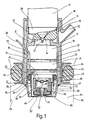
- a fuel injection device for an internal combustion engine a fuel injector 10 on that in the usual way in its outlet side End face 11 has a spray opening 12, the a valve seat 14 cooperating with a valve needle 13 assigned.
- valve needle 13 one extending through the spray opening 12
- Spray pin 13 'on when the injector is open 10 to form a hosed fuel lamella so in the outlet opening 12 is arranged that in a spray area 15 hosed fuel fins essentially is cone-shaped.
- the formation of the fuel lamella or one shaped in any other desired manner or multi-part fuel jet can also on others Way to be achieved. So it is z. B. possible, a spray orifice plate to be provided with one or more spray holes or to design the outlet opening as an annular gap.
- a Fuel evaporator 16 placed tightly on a housing 17th with a sleeve-shaped mounting section 18.
- a on Inner circumference of the mounting section 18 formed ring web 19 engages in an end of the injection valve on the intake pipe side 10 provided annular groove 20 and thus holds the fuel evaporator 16 close to the injection valve 10.
- the attachment The fuel vaporizer 16 can also be used in other ways respectively.
- a tight press fit connection is also conceivable between fuel evaporator 16 and injection valve 10th
- the heating elements 23 are for power supply via a electrical line 25 which is electrically insulated but gas-tight is inserted into the housing 17, with a not shown Power source connected.
- the heating elements 23 consist Washers. But there are also other geometric configurations of the heating elements 23 conceivable.
- FIG. 2 shows, for example, two sleeve-shaped heating elements 23 ', which are arranged coaxially to one another and to the receiving sleeve 22 and are held by a common holding part 24.
- the holding part 24 is on the side facing away from the injection valve 10 Side of the heating elements 23 'provided and in not shown in such a way that it is the exit not hindered by fuel vapor from the evaporator area 21.
- the inner heating element 23 ' is expediently shown in Axial direction shorter than the outer.
- For electrical Connection is the heating elements 23 'via a branch line 26 connected to line 25.
- Fig. 3 shows a further embodiment of the heating elements 23, at of the heating elements 23 "concentric to each other and to the receiving sleeve 22 are arranged.
- the two heating elements 23 " are held on holding parts 24 at their axial ends.
- the evaporator area 21 is between the heating elements 23 " doing so with a porous material 27, e.g. B. with porous ceramics or fine metal wool, filled for heat transfer to further improve the fuel.
- the individual Heating elements 23, 23 'and 23 made of a PTC resistance material, So from a resistance material with a positive temperature coefficients exist. It is also possible, an NTC resistance material, i.e. a resistance material to be used with a negative temperature coefficient. In this case, external temperature control is required provided.
- a temperature control device not shown, the in a control unit for the Internal combustion engine can be integrated, the temperature the heating elements 23, 23 'and 23 "corresponding temperature signal fed. To form the temperature signal can either the temperature-dependent internal resistance of the heating elements 23, 23 'and 23 "are used, or there is an in the drawing, not shown temperature sensor on one of the heating elements 23, 23 'and 23 "arranged.
- heating elements 23, 23 'and 23 "from one NTC resistance material is particularly advantageous if if due to different fuel throughputs Temperature control for the heating elements 23, 23 'and 23 "anyway is required.
- the exhaust valve 30, which has an acicular valve body 31st with a closing head 32 on its remote from the injection valve 10 End and includes a valve seat 33 is in one Holding sleeve 34 arranged on the outside of a assembled state against the inside of the receiving sleeve 22
- Sealing ring 35 carries between a radially outwardly projecting Flange 36 of the holding sleeve 34 and also one outwardly projecting flange 37 one on the outside on the holding sleeve 34 arranged support sleeve 38 is inserted.
- the holding sleeve 34 On hers outlet-side end, the holding sleeve 34 has a radial inwardly extending retaining flange 34 'on which a Valve seat 33 supporting valve seat body 39 is attached.
- a closing spring 41 which is expedient is designed as a compression spring and between the valve seat body 39 and an end facing away from the closing head 32 of the valve body 31 arranged support plate 42 clamped is, towards the injection valve 10 in its closed position biased, in which the the outer region of the exhaust valve 30 associated closing head 32 abuts the valve seat 33.
- the valve closing force generated by the closing spring 41 becomes preset so that the exhaust valve 30 at an inner Pressure from 2000 hPa to 4000 hPa opens.
- the z. B. from a permanent magnet is provided.
- the outlet valve 30 is another, sleeve-shaped heating element 43 assigned, which is attached to the valve seat body 39 and the valve body 31 and the closing spring 41 surrounds.
- the heating element 43 is on the one hand with the electrical Line 25 and on the other hand with an outer peripheral portion connected to the holding sleeve 34.
- Casing 17 comprising casing sleeve 50 is provided, which with the housing 17 together an annular cylindrical gas channel 51 forms the air on the inlet side or preferably from the internal combustion engine recirculated exhaust gas via a connection piece 52 can be fed.
- the jacket sleeve 50 flange-like bent inwards and lies with the bent Section 53 close to the housing 17.
- the housing 17 has at its end facing away from the injection valve 10 in Fuel injection direction seen behind the investment area of the sealing ring 35 has a plurality of outlet openings 54, arranged circumferentially at equal intervals, for example are.
- To guide 34 extends that facing away from the injector 10 End of the housing 17 or the receiving sleeve 22 to front end of the holding sleeve 34 for the outlet valve 30 and thus forms together with the holding sleeve 34 surrounding it exit cylinder 55 in the form of a ring cylinder for the air or exhaust flow front section the receiving sleeve 22, which surrounds the outlet channel 55 on the outside, can be slightly tapered inwards.
- the gas channel 51 comprising the fuel evaporator 16 is designed together with the outlet openings 54 so that air supplied or exhaust gas recirculated from the internal combustion engine at high speed from between the holding sleeve 34 and receiving sleeve 22 formed, annular-gap-shaped gas outlet opening 56 exits.
- Suction pipe 60 is a radially U-shaped in cross section externally open retaining ring 61 is provided on the casing sleeve 50, in which a sealing ring 62 is inserted, which in the installed state on an inner wall 63 of a corresponding opening 64 fits tightly in the intake manifold 60.
- the retaining ring 61 is used together with the sealing ring 62 as thermal insulation between the Fuel evaporator 16 and the intake manifold 60 of the internal combustion engine. If the sleeve 50 to form the fuel evaporator 16 comprehensive gas channel 51 is not provided is the retaining ring 61 directly on the housing 17th placed.
- Heating element 43 electrically heated. From the fuel meter Injection valve 10 in the spray area 15 in the fuel evaporator 16 injected fuel gets in from there the evaporator area 21, whereby it is applied to the heating elements 23, 23 ', 23 ", the holding parts 24 and in the embodiment according to FIG. 3 also on the porous material 27 in the evaporator region 21 strikes, is heated and at least partially evaporated. Depending on the shape of the sprayed fuel jet can also some of the liquid fuel on the inner surface the receiving sleeve 22 hit. There he will when the receiving sleeve 22 is sufficiently heated, also evaporated.
- the evaporation of fuel increases the pressure inside of the evaporator 16 to the preset opening pressure is reached, the outlet valve 30 opens and Fuel flows out.
- the outflowing, partly vaporous, partly liquid, hot fuel is from the heating element 43 and the exhaust valve 30 heated therefrom additionally heated.
- the heating elements are to provide a fuel / air mixture 23, 23 'and 23 "are designed accordingly and / or by the temperature control device controlled accordingly.
- a major advantage of the fuel evaporator according to the invention 16 is that the injection of liquid Fuel and the discharge of the hot fuel-fuel vapor mixture without affecting fuel metering can overlap in time without the metering function of the injection valve 10 is impaired.
- the fuel evaporator 16 is thereby heated up, and there is fuel evaporation reach without additional electrical heating.
- the air can be introduced into the gas channel 51 Support fuel atomization.
Landscapes
- Engineering & Computer Science (AREA)
- Chemical & Material Sciences (AREA)
- Combustion & Propulsion (AREA)
- Mechanical Engineering (AREA)
- General Engineering & Computer Science (AREA)
- Fuel-Injection Apparatus (AREA)
Claims (10)
- Dispositif d'injection de carburant pour un moteur à combustion interne comprenant un injecteur (10) de dosage et un évaporateur de carburant (16) installé du côté de la tubulure d'aspiration, devant l'orifice d'éjection (12) de l'injecteur (10), cet évaporateur ayant une zone d'évaporation (21) avec au moins un élément chauffant électrique (23, 23', 23") et une soupape d'éjection (30) qui ferme la zone d'évaporation (21) du côté de la sortie,
caractérisé en ce que
l'élément chauffant (23, 23', 23") associé à la zone d'évaporation (21) est réalisé comme premier élément chauffant (23, 23', 23") et au niveau de la soupape d'éjection (30) on a directement un second élément chauffant électrique (43), installé indépendamment d'au moins un premier élément chauffant (23, 23', 23"). - Dispositif d'injection de carburant selon la revendication 1,
caractérisé en ce que
la soupape d'éjection (30) comporte un corps de soupape (31) poussé de préférence par un ressort de fermeture réglable dans sa position de fermeture et qui est déplacé par la pression de l'évaporateur de carburant (16) dans sa position d'ouverture lorsque la force engendrée par la pression exercée sur le corps de soupape (31) dépasse la force de fermeture. - Dispositif d'injection de carburant selon la revendication 2,
caractérisé en ce que
le second élément chauffant (43) associé à la soupape d'éjection (30) est relié à un corps formant siège de soupape (39) et entoure suivant une forme de cylindre annulaire le corps de soupape (31) ainsi qu'un élément générant la force de fermeture de préférence un ressort de fermeture (41). - Dispositif d'injection de carburant selon l'une quelconque des revendications précédentes,
caractérisé en ce qu'
au moins un premier élément chauffant (23, 23', 23") est réalisé en une matière résistante ayant un coefficient de température positif. - Dispositif d'injection de carburant selon l'une quelconque des revendications 1 à 3,
caractérisé en ce qu'
au moins un premier élément chauffant (23, 23', 23") est réalisé en une matière résistante ayant un coefficient de température négatif. - Dispositif d'injection de carburant selon l'une quelconque des revendications 4 ou 5,
caractérisé en ce qu'
au moins l'un des premiers éléments chauffants (23, 23', 23") comporte une installation de commande de température servant à la régulation du courant de chauffage alimentant au moins un premier élément chauffant (23, 23', 23") et recevant le signal de température correspondant à la température de l'élément chauffant. - Dispositif d'injection de carburant selon la revendication 6,
caractérisé en ce que
pour former le signal de température, il est prévu au moins un capteur de température associé à l'un des premiers éléments chauffants (23, 23', 23"). - Dispositif d'injection de carburant selon l'une quelconque des revendications précédentes,
caractérisé en ce que
dans la zone d'évaporation (21) il y a au moins deux premiers éléments chauffants (23, 23', 23") et le volume libre compris entre les premiers éléments chauffants (23, 23', 23") est rempli d'une matière poreuse (27) de préférence de la céramique poreuse ou de la laine métallique fine favorisant le contact thermique avec les premiers éléments chauffants (23, 23', 23"). - Dispositif d'injection de carburant selon l'une quelconque des revendications précédentes,
caractérisé en ce que
l'évaporateur de carburant (16) est entouré par un canal de gaz (51) dont l'entrée reçoit de l'air et de préférence des gaz d'échappement ré-injectés et cet évaporateur débouche dans un canal de sortie (55) annulaire cylindrique entourant le manchon de fixation (34) de la soupape d'éjection (30), canal dont l'orifice de sortie de gaz (56), de forme annulaire, se situe essentiellement dans un plan avec une sortie d'un orifice traversant (40) de la soupape d'éjection (30). - Dispositif d'injection de carburant selon la revendication 9,
caractérisé en ce que
les moyens de guidage de gaz formés du canal de gaz (51) et du canal de sortie (55) entourent à la fois au moins un premier élément chauffant (23, 23', 23") et un second élément chauffant (43).
Applications Claiming Priority (3)
| Application Number | Priority Date | Filing Date | Title |
|---|---|---|---|
| DE19542317A DE19542317A1 (de) | 1995-11-14 | 1995-11-14 | Kraftstoffeinspritzvorrichtung für einen Verbrennungsmotor |
| DE19542317 | 1995-11-14 | ||
| PCT/DE1996/001512 WO1997018390A1 (fr) | 1995-11-14 | 1996-08-14 | Dispositif d'injection de carburant pour moteur a combustion interne |
Publications (2)
| Publication Number | Publication Date |
|---|---|
| EP0803027A1 EP0803027A1 (fr) | 1997-10-29 |
| EP0803027B1 true EP0803027B1 (fr) | 2002-03-20 |
Family
ID=7777364
Family Applications (1)
| Application Number | Title | Priority Date | Filing Date |
|---|---|---|---|
| EP96931751A Expired - Lifetime EP0803027B1 (fr) | 1995-11-14 | 1996-08-14 | Dispositif d'injection de carburant pour moteur a combustion interne |
Country Status (5)
| Country | Link |
|---|---|
| US (1) | US5947091A (fr) |
| EP (1) | EP0803027B1 (fr) |
| JP (1) | JPH10512651A (fr) |
| DE (2) | DE19542317A1 (fr) |
| WO (1) | WO1997018390A1 (fr) |
Families Citing this family (48)
| Publication number | Priority date | Publication date | Assignee | Title |
|---|---|---|---|---|
| US5758826A (en) | 1996-03-29 | 1998-06-02 | Siemens Automotive Corporation | Fuel injector with internal heater |
| DE19749471A1 (de) * | 1997-11-08 | 1999-05-12 | Bosch Gmbh Robert | Einrichtung zur Verdampfung von Brennstoff |
| DE19983386T1 (de) * | 1998-07-17 | 2001-06-13 | Timothy Wyse | Kraftstoffverdampfungssystem |
| AU4780300A (en) * | 1999-05-24 | 2000-12-12 | Nishiyama, Kenichi | Method of improving petroleum fuel combustion and device therefor |
| US6957013B2 (en) * | 2001-06-08 | 2005-10-18 | Algas-Sdi International Llc | Fluid heater |
| US6816669B2 (en) | 2001-06-08 | 2004-11-09 | Algas-Sdi International Llc | Vaporizer with capacity control valve |
| US6820598B2 (en) | 2002-03-22 | 2004-11-23 | Chrysalis Technologies Incorporated | Capillary fuel injector with metering valve for an internal combustion engine |
| US6779513B2 (en) | 2002-03-22 | 2004-08-24 | Chrysalis Technologies Incorporated | Fuel injector for an internal combustion engine |
| US7249596B2 (en) * | 2002-03-22 | 2007-07-31 | Philip Morris Usa Inc. | Fuel system for an internal combustion engine and method for controlling same |
| US6913004B2 (en) | 2002-03-22 | 2005-07-05 | Chrysalis Technologies Incorporated | Fuel system for an internal combustion engine and method for controlling same |
| US6913005B2 (en) | 2002-03-22 | 2005-07-05 | Chrysalis Technologies Incorporated | System and methodology for purging fuel from a fuel injector during start-up |
| MXPA04009181A (es) | 2002-03-22 | 2005-06-20 | Chrysalis Tech Inc | Inyector de combustible para motor de combustion interna. |
| US7032576B2 (en) | 2002-05-10 | 2006-04-25 | Philip Morris Usa Inc. | Capillary heating control and fault detection system and methodology for fuel system in an internal combustion engine |
| US7357124B2 (en) * | 2002-05-10 | 2008-04-15 | Philip Morris Usa Inc. | Multiple capillary fuel injector for an internal combustion engine |
| US6758194B2 (en) | 2002-11-12 | 2004-07-06 | Emission Controls Corporation | Parallel vaporized fuel system |
| DE10256453A1 (de) * | 2002-12-03 | 2004-06-24 | Robert Bosch Gmbh | Dosiereinrichtung |
| DE602004029049D1 (de) * | 2003-07-01 | 2010-10-21 | Philip Morris Usa Inc | Einrichtung zur leistungsabgabe und hybride kraftstoff-verdampfungseinrichtung hierzu |
| US6843236B1 (en) | 2003-07-14 | 2005-01-18 | Michael Shetley | Multi-phase fuel system |
| JP4567687B2 (ja) | 2003-10-30 | 2010-10-20 | フィリップ・モリス・ユーエスエイ・インコーポレイテッド | 内燃機関用の多重毛細管燃料噴射器 |
| US20050188963A1 (en) * | 2004-03-01 | 2005-09-01 | Gofar Laboratories | System, vaporizing fuel in vehicle |
| US20050193993A1 (en) * | 2004-03-04 | 2005-09-08 | Dale Thomas D. | Fuel vapor systems for internal combustion engines |
| US7337768B2 (en) * | 2004-05-07 | 2008-03-04 | Philip Morris Usa Inc. | Multiple capillary fuel injector for an internal combustion engine |
| DE102007004799A1 (de) * | 2007-01-31 | 2008-08-07 | Robert Bosch Gmbh | Dosiereinrichtung |
| GB2454022A (en) * | 2007-10-27 | 2009-04-29 | Uav Engines Ltd | Fuel heating apparatus to aid cold starts in low ambient temperatures |
| US8074625B2 (en) | 2008-01-07 | 2011-12-13 | Mcalister Technologies, Llc | Fuel injector actuator assemblies and associated methods of use and manufacture |
| US8225768B2 (en) | 2008-01-07 | 2012-07-24 | Mcalister Technologies, Llc | Integrated fuel injector igniters suitable for large engine applications and associated methods of use and manufacture |
| US7628137B1 (en) | 2008-01-07 | 2009-12-08 | Mcalister Roy E | Multifuel storage, metering and ignition system |
| US8365700B2 (en) | 2008-01-07 | 2013-02-05 | Mcalister Technologies, Llc | Shaping a fuel charge in a combustion chamber with multiple drivers and/or ionization control |
| US8635985B2 (en) | 2008-01-07 | 2014-01-28 | Mcalister Technologies, Llc | Integrated fuel injectors and igniters and associated methods of use and manufacture |
| US8561598B2 (en) | 2008-01-07 | 2013-10-22 | Mcalister Technologies, Llc | Method and system of thermochemical regeneration to provide oxygenated fuel, for example, with fuel-cooled fuel injectors |
| US8413634B2 (en) | 2008-01-07 | 2013-04-09 | Mcalister Technologies, Llc | Integrated fuel injector igniters with conductive cable assemblies |
| US8387599B2 (en) | 2008-01-07 | 2013-03-05 | Mcalister Technologies, Llc | Methods and systems for reducing the formation of oxides of nitrogen during combustion in engines |
| EP2470485A4 (fr) | 2009-08-27 | 2012-12-26 | Mcalister Technologies Llc | Isolateur céramique et ses procédés d'utilisation et de fabrication |
| CN102713244A (zh) | 2009-08-27 | 2012-10-03 | 麦卡利斯特技术有限责任公司 | 在具有多个驱动器和/或电离控制的燃烧室中成形供应燃料 |
| WO2011028225A1 (fr) * | 2009-08-27 | 2011-03-10 | Mcalister Technoligies, Llc | Procédé et système de régénération thermo-chimique en vue de l'obtention d'un combustible oxygéné, par exemple, pour des injecteurs refroidis par carburant |
| KR20120086375A (ko) | 2009-12-07 | 2012-08-02 | 맥알리스터 테크놀로지즈 엘엘씨 | 연료 인젝터 및 점화기를 위한 적응 제어 시스템 |
| CN102844540A (zh) | 2010-02-13 | 2012-12-26 | 麦卡利斯特技术有限责任公司 | 用于自适应地冷却发动机中的燃烧室的方法和系统 |
| US20110297753A1 (en) | 2010-12-06 | 2011-12-08 | Mcalister Roy E | Integrated fuel injector igniters configured to inject multiple fuels and/or coolants and associated methods of use and manufacture |
| US8205805B2 (en) | 2010-02-13 | 2012-06-26 | Mcalister Technologies, Llc | Fuel injector assemblies having acoustical force modifiers and associated methods of use and manufacture |
| US8528519B2 (en) | 2010-10-27 | 2013-09-10 | Mcalister Technologies, Llc | Integrated fuel injector igniters suitable for large engine applications and associated methods of use and manufacture |
| US8091528B2 (en) | 2010-12-06 | 2012-01-10 | Mcalister Technologies, Llc | Integrated fuel injector igniters having force generating assemblies for injecting and igniting fuel and associated methods of use and manufacture |
| US8820275B2 (en) | 2011-02-14 | 2014-09-02 | Mcalister Technologies, Llc | Torque multiplier engines |
| CN103890343B (zh) | 2011-08-12 | 2015-07-15 | 麦卡利斯特技术有限责任公司 | 用于改进的发动机冷却及能量产生的系统和方法 |
| US8919377B2 (en) | 2011-08-12 | 2014-12-30 | Mcalister Technologies, Llc | Acoustically actuated flow valve assembly including a plurality of reed valves |
| US9115325B2 (en) | 2012-11-12 | 2015-08-25 | Mcalister Technologies, Llc | Systems and methods for utilizing alcohol fuels |
| KR102409471B1 (ko) * | 2014-12-22 | 2022-06-16 | 가부시키가이샤 호리바 에스텍 | 유체 가열기 |
| EP3153697A1 (fr) * | 2015-10-09 | 2017-04-12 | Continental Automotive GmbH | Agencement d'ensemble de soupape pour soupape d'injection et ladite soupape |
| US20190170037A1 (en) * | 2017-12-06 | 2019-06-06 | Continental Automotive Systems, Inc. | Diesel dosing unit having an anti-coking injector assembly, and methods of constructing and utilizing same |
Citations (1)
| Publication number | Priority date | Publication date | Assignee | Title |
|---|---|---|---|---|
| WO1996024764A1 (fr) * | 1995-02-07 | 1996-08-15 | Siemens Aktiengesellschaft | Dispositif de dosage et d'atomisation de fluide |
Family Cites Families (14)
| Publication number | Priority date | Publication date | Assignee | Title |
|---|---|---|---|---|
| DE841973C (de) * | 1936-01-14 | 1952-06-23 | Daimler Benz Ag | Vorrichtung zum Aufbereiten und Einfuehren von Brennstoff in Brennkraftmaschinen mit Selbstzuendung |
| GB1282016A (en) * | 1969-07-21 | 1972-07-19 | Brian Thomas Croft | Fuel injectors for internal combustion engines |
| DE2057972C3 (de) * | 1970-11-25 | 1975-06-26 | Robert Bosch Gmbh, 7000 Stuttgart | Für fremdgezündete Brennkraftmaschinen bestimmte Kraftstoffeinspritzvorrichtung für den Kaltstart |
| US3999525A (en) * | 1970-11-25 | 1976-12-28 | Robert Bosch G.M.B.H. | Apparatus for the cold starting and warming run of spark plug-ignited internal combustion engines |
| DE2210250C2 (de) * | 1972-03-03 | 1982-05-13 | Robert Bosch Gmbh, 7000 Stuttgart | Kraftstoffeinspritzvorrichtung für den Kaltstart und den Warmlauf fremdgezündeter Brennkraftmaschinen |
| US4137872A (en) * | 1976-02-25 | 1979-02-06 | Loflin Max G | Fuel vaporizing device for internal combustion engines |
| JPS5453714A (en) * | 1977-10-06 | 1979-04-27 | Toyota Motor Corp | Internal combustion engine fuel injector |
| DE3240554C2 (de) * | 1982-11-03 | 1993-10-07 | Bosch Gmbh Robert | Kraftstoffeinspritzventil für eine Brennkraftmaschine |
| DE3327773A1 (de) * | 1983-05-13 | 1984-11-15 | Robert Bosch Gmbh, 7000 Stuttgart | Einrichtung zur kraftstoffeinspritzung in brennraeume |
| DE3335298A1 (de) * | 1983-09-29 | 1985-04-18 | Robert Bosch Gmbh, 7000 Stuttgart | Einrichtung zum einspritzen von kraftstoff in brennraeume von brennkraftmaschinen |
| GB2263501A (en) * | 1992-01-16 | 1993-07-28 | Ford Motor Co | I.c.engine fuel vaporiser having a porous electric heating element. |
| JPH05340325A (ja) * | 1992-04-07 | 1993-12-21 | Unisia Jecs Corp | アシストエア式燃料噴射装置 |
| GB2281101B (en) * | 1993-07-19 | 1997-05-07 | Univ London | Combined fuel vaporiser and atomiser |
| DE4446242A1 (de) * | 1994-12-23 | 1996-06-27 | Bosch Gmbh Robert | Kraftstoffeinspritzvorrichtung für einen Verbrennungsmotor |
-
1995
- 1995-11-14 DE DE19542317A patent/DE19542317A1/de not_active Withdrawn
-
1996
- 1996-08-14 JP JP9518485A patent/JPH10512651A/ja not_active Abandoned
- 1996-08-14 WO PCT/DE1996/001512 patent/WO1997018390A1/fr not_active Ceased
- 1996-08-14 DE DE59608923T patent/DE59608923D1/de not_active Expired - Fee Related
- 1996-08-14 US US08/860,916 patent/US5947091A/en not_active Expired - Fee Related
- 1996-08-14 EP EP96931751A patent/EP0803027B1/fr not_active Expired - Lifetime
Patent Citations (1)
| Publication number | Priority date | Publication date | Assignee | Title |
|---|---|---|---|---|
| WO1996024764A1 (fr) * | 1995-02-07 | 1996-08-15 | Siemens Aktiengesellschaft | Dispositif de dosage et d'atomisation de fluide |
Also Published As
| Publication number | Publication date |
|---|---|
| DE59608923D1 (de) | 2002-04-25 |
| EP0803027A1 (fr) | 1997-10-29 |
| DE19542317A1 (de) | 1997-05-15 |
| WO1997018390A1 (fr) | 1997-05-22 |
| US5947091A (en) | 1999-09-07 |
| JPH10512651A (ja) | 1998-12-02 |
Similar Documents
| Publication | Publication Date | Title |
|---|---|---|
| EP0803027B1 (fr) | Dispositif d'injection de carburant pour moteur a combustion interne | |
| DE69724172T2 (de) | Vorrichtung zur direkten Kraftstoffeinspritzung und mit dieser Vorrichtung ausgestatteter Verbrennungsmotor | |
| EP0677653B1 (fr) | Dispositif pour atomiser du carburant | |
| DE3032067C2 (fr) | ||
| DE2843534C2 (de) | Kraftstoffliefereinrichtung für eine Brennkraftmaschine | |
| DE60220456T2 (de) | Kraftstoffzufuhrsystem | |
| EP0770175A1 (fr) | Dispositif d'injection de carburant destine a un moteur a combustion interne | |
| EP0151793B1 (fr) | Buse d'injection de combustible pour moteurs à combustion interne | |
| DE3032066A1 (de) | Gemischbildungsanlage fuer gemischverdichtende fremgezuendete brennkraftmaschinen | |
| DE3010078A1 (de) | Mit fluessigem brennstoff betriebener brenner fuer heizvorrichtungen | |
| EP0148837B1 (fr) | Dispositif d'injection de carburant dans un ecoulement secondaire d'air de combustion d'une chambre de combustion | |
| EP1291579B1 (fr) | Buse pour la pulvérisation d'un carburant liquide | |
| DE60108178T2 (de) | Kaltstartsystem für dieselmotoren mit schneller direkteinspritzung | |
| EP1327820A1 (fr) | Atténuateur actif de bruit pour systèmes de gaz d'échappement | |
| DE3307666A1 (de) | Einrichtung zum einspritzen von kraftstoff in brennraeume, insbesondere in brennkammern von dieselmotoren | |
| DE4309833C2 (de) | Verfahren und Vorrichtung zum Betrieb einer Brennkraftmaschine oder Feuerungsstätte | |
| DE3716411A1 (de) | Verdampferkerze | |
| WO1997022799A1 (fr) | Dispositif d'injection de carburant pour moteurs a combustion interne | |
| DE19843317A1 (de) | Beheiztes Einspritzventil für fremdgezündete Brennkraftmaschinen | |
| DE4242091C2 (de) | Vorrichtung zum Starten des Regenerationsbrenners eines Partikelfiltersystems bei niedrigen Temperaturen | |
| DE19506711C1 (de) | Flammglühkerze für eine Dieselbrennkraftmaschine | |
| DE2310326A1 (de) | Kraftstoff-einspritzduese fuer verbrennungskraftmaschinen | |
| DE2621555A1 (de) | Kraftstoffeinspritzanlage | |
| DE19542318A1 (de) | Kraftstoffeinspritzvorrichtung für einen Verbrennungsmotor | |
| DE4412448C2 (de) | Einrichtung zur Vernebelung von Kraftstoff |
Legal Events
| Date | Code | Title | Description |
|---|---|---|---|
| PUAI | Public reference made under article 153(3) epc to a published international application that has entered the european phase |
Free format text: ORIGINAL CODE: 0009012 |
|
| AK | Designated contracting states |
Kind code of ref document: A1 Designated state(s): DE FR GB IT |
|
| 17P | Request for examination filed |
Effective date: 19971124 |
|
| 17Q | First examination report despatched |
Effective date: 19991028 |
|
| GRAG | Despatch of communication of intention to grant |
Free format text: ORIGINAL CODE: EPIDOS AGRA |
|
| GRAG | Despatch of communication of intention to grant |
Free format text: ORIGINAL CODE: EPIDOS AGRA |
|
| GRAH | Despatch of communication of intention to grant a patent |
Free format text: ORIGINAL CODE: EPIDOS IGRA |
|
| GRAH | Despatch of communication of intention to grant a patent |
Free format text: ORIGINAL CODE: EPIDOS IGRA |
|
| REG | Reference to a national code |
Ref country code: GB Ref legal event code: IF02 |
|
| GRAA | (expected) grant |
Free format text: ORIGINAL CODE: 0009210 |
|
| AK | Designated contracting states |
Kind code of ref document: B1 Designated state(s): DE FR GB IT |
|
| REF | Corresponds to: |
Ref document number: 59608923 Country of ref document: DE Date of ref document: 20020425 |
|
| GBT | Gb: translation of ep patent filed (gb section 77(6)(a)/1977) |
Effective date: 20020529 |
|
| ET | Fr: translation filed | ||
| PLBE | No opposition filed within time limit |
Free format text: ORIGINAL CODE: 0009261 |
|
| STAA | Information on the status of an ep patent application or granted ep patent |
Free format text: STATUS: NO OPPOSITION FILED WITHIN TIME LIMIT |
|
| 26N | No opposition filed |
Effective date: 20021223 |
|
| PGFP | Annual fee paid to national office [announced via postgrant information from national office to epo] |
Ref country code: GB Payment date: 20030729 Year of fee payment: 8 |
|
| PGFP | Annual fee paid to national office [announced via postgrant information from national office to epo] |
Ref country code: FR Payment date: 20030819 Year of fee payment: 8 |
|
| PG25 | Lapsed in a contracting state [announced via postgrant information from national office to epo] |
Ref country code: GB Free format text: LAPSE BECAUSE OF NON-PAYMENT OF DUE FEES Effective date: 20040814 |
|
| GBPC | Gb: european patent ceased through non-payment of renewal fee |
Effective date: 20040814 |
|
| PG25 | Lapsed in a contracting state [announced via postgrant information from national office to epo] |
Ref country code: FR Free format text: LAPSE BECAUSE OF NON-PAYMENT OF DUE FEES Effective date: 20050429 |
|
| REG | Reference to a national code |
Ref country code: FR Ref legal event code: ST |
|
| PG25 | Lapsed in a contracting state [announced via postgrant information from national office to epo] |
Ref country code: IT Free format text: LAPSE BECAUSE OF NON-PAYMENT OF DUE FEES;WARNING: LAPSES OF ITALIAN PATENTS WITH EFFECTIVE DATE BEFORE 2007 MAY HAVE OCCURRED AT ANY TIME BEFORE 2007. THE CORRECT EFFECTIVE DATE MAY BE DIFFERENT FROM THE ONE RECORDED. Effective date: 20050814 |
|
| PGFP | Annual fee paid to national office [announced via postgrant information from national office to epo] |
Ref country code: DE Payment date: 20051021 Year of fee payment: 10 |
|
| PG25 | Lapsed in a contracting state [announced via postgrant information from national office to epo] |
Ref country code: DE Free format text: LAPSE BECAUSE OF NON-PAYMENT OF DUE FEES Effective date: 20070301 |