EP0803042B1 - Dispositif pour epurer des gaz brules - Google Patents
Dispositif pour epurer des gaz brules Download PDFInfo
- Publication number
- EP0803042B1 EP0803042B1 EP96900836A EP96900836A EP0803042B1 EP 0803042 B1 EP0803042 B1 EP 0803042B1 EP 96900836 A EP96900836 A EP 96900836A EP 96900836 A EP96900836 A EP 96900836A EP 0803042 B1 EP0803042 B1 EP 0803042B1
- Authority
- EP
- European Patent Office
- Prior art keywords
- fact
- burner
- cover
- combustion chamber
- outer pipe
- Prior art date
- Legal status (The legal status is an assumption and is not a legal conclusion. Google has not performed a legal analysis and makes no representation as to the accuracy of the status listed.)
- Expired - Lifetime
Links
Images


Classifications
-
- F—MECHANICAL ENGINEERING; LIGHTING; HEATING; WEAPONS; BLASTING
- F23—COMBUSTION APPARATUS; COMBUSTION PROCESSES
- F23G—CREMATION FURNACES; CONSUMING WASTE PRODUCTS BY COMBUSTION
- F23G7/00—Incinerators or other apparatus for consuming industrial waste, e.g. chemicals
- F23G7/06—Incinerators or other apparatus for consuming industrial waste, e.g. chemicals of waste gases or noxious gases, e.g. exhaust gases
-
- F—MECHANICAL ENGINEERING; LIGHTING; HEATING; WEAPONS; BLASTING
- F23—COMBUSTION APPARATUS; COMBUSTION PROCESSES
- F23J—REMOVAL OR TREATMENT OF COMBUSTION PRODUCTS OR COMBUSTION RESIDUES; FLUES
- F23J15/00—Arrangements of devices for treating smoke or fumes
- F23J15/02—Arrangements of devices for treating smoke or fumes of purifiers, e.g. for removing noxious material
- F23J15/04—Arrangements of devices for treating smoke or fumes of purifiers, e.g. for removing noxious material using washing fluids
-
- B—PERFORMING OPERATIONS; TRANSPORTING
- B01—PHYSICAL OR CHEMICAL PROCESSES OR APPARATUS IN GENERAL
- B01D—SEPARATION
- B01D53/00—Separation of gases or vapours; Recovering vapours of volatile solvents from gases; Chemical or biological purification of waste gases, e.g. engine exhaust gases, smoke, fumes, flue gases, aerosols
- B01D53/34—Chemical or biological purification of waste gases
- B01D53/46—Removing components of defined structure
-
- B—PERFORMING OPERATIONS; TRANSPORTING
- B01—PHYSICAL OR CHEMICAL PROCESSES OR APPARATUS IN GENERAL
- B01D—SEPARATION
- B01D53/00—Separation of gases or vapours; Recovering vapours of volatile solvents from gases; Chemical or biological purification of waste gases, e.g. engine exhaust gases, smoke, fumes, flue gases, aerosols
- B01D53/34—Chemical or biological purification of waste gases
- B01D53/74—General processes for purification of waste gases; Apparatus or devices specially adapted therefor
- B01D53/77—Liquid phase processes
- B01D53/78—Liquid phase processes with gas-liquid contact
-
- F—MECHANICAL ENGINEERING; LIGHTING; HEATING; WEAPONS; BLASTING
- F23—COMBUSTION APPARATUS; COMBUSTION PROCESSES
- F23G—CREMATION FURNACES; CONSUMING WASTE PRODUCTS BY COMBUSTION
- F23G7/00—Incinerators or other apparatus for consuming industrial waste, e.g. chemicals
- F23G7/06—Incinerators or other apparatus for consuming industrial waste, e.g. chemicals of waste gases or noxious gases, e.g. exhaust gases
- F23G7/061—Incinerators or other apparatus for consuming industrial waste, e.g. chemicals of waste gases or noxious gases, e.g. exhaust gases with supplementary heating
- F23G7/065—Incinerators or other apparatus for consuming industrial waste, e.g. chemicals of waste gases or noxious gases, e.g. exhaust gases with supplementary heating using gaseous or liquid fuel
-
- B—PERFORMING OPERATIONS; TRANSPORTING
- B01—PHYSICAL OR CHEMICAL PROCESSES OR APPARATUS IN GENERAL
- B01D—SEPARATION
- B01D2258/00—Sources of waste gases
- B01D2258/02—Other waste gases
- B01D2258/0216—Other waste gases from CVD treatment or semi-conductor manufacturing
-
- F—MECHANICAL ENGINEERING; LIGHTING; HEATING; WEAPONS; BLASTING
- F23—COMBUSTION APPARATUS; COMBUSTION PROCESSES
- F23G—CREMATION FURNACES; CONSUMING WASTE PRODUCTS BY COMBUSTION
- F23G2209/00—Specific waste
- F23G2209/14—Gaseous waste or fumes
- F23G2209/142—Halogen gases, e.g. silane
-
- F—MECHANICAL ENGINEERING; LIGHTING; HEATING; WEAPONS; BLASTING
- F23—COMBUSTION APPARATUS; COMBUSTION PROCESSES
- F23J—REMOVAL OR TREATMENT OF COMBUSTION PRODUCTS OR COMBUSTION RESIDUES; FLUES
- F23J2219/00—Treatment devices
- F23J2219/40—Sorption with wet devices, e.g. scrubbers
Definitions
- the invention relates to a device for cleaning Exhaust gases, in particular exhaust gases from CVD, plasma etching or similar processes, with at least one combustion chamber in the vertical Arrangement within an outer tube through a umbrella-like cover is limited at the top and an interior or external mixing burner, the fuel gas nozzles in the Protrude into the combustion chamber, with the burner fuel gas, oxygen, or air and exhaust gas is supplied, and means for supply and derivation of sorbent or sorbent and oxidant in a washroom above the combustion chamber.
- Such exhaust gases are usually cleaned in two Stages by burning the exhaust gases first and then be cleaned in a wash.
- the combustion of the exhaust gases, or their oxidation takes place here with the help of gas-powered Burners within a combustion chamber.
- EP 0 346 893 B1 describes such a device for Exhaust gas cleaning has become known from a post bottom body essentially closed and top body open with a circular cross section.
- This basic body consists of a cylindrical outer wall and a concentric one to this arranged inner wall, which is a combustion chamber limited.
- This body protrudes from below Burner to burn the together with the fuel gas Exhaust gases fed into the burner into the combustion chamber.
- the top of the combustion chamber is limited by a splash guard, above which there is a washing or rinsing chamber.
- In this rinsing chamber is a centrally arranged
- a nozzle that is used to generate a spray cone of a detergent is, with the aerosols and solid components from the burned Exhaust gas can be flushed out. With the splash guard prevents detergent from entering the combustion chamber and thus is sprayed into the burner or into the flame.
- the rinsed out residues are run along with the detergent the inside of the cylindrical outer wall downwards and derived through a drain located in the base body.
- US 5,123,836 also shows a device for combustion of exhaust gases containing toxic gases within a combustion chamber.
- a Arranged burner which is directed downward into the combustion chamber Burner flame generated.
- the burner is besides Fuel gas supplied the toxic gas to be burned.
- spray nozzles which are a water mist generate, with the help of the combustion emerging microparticles are washed out. It will burned gas quickly cooled down at the same time.
- spray nozzles which are a water mist generate, with the help of the combustion emerging microparticles are washed out. It will burned gas quickly cooled down at the same time.
- on the inner wall of the combustion chamber in a tangential direction downward flowing water film produced. This water film prevents the deposition of microparticles on the inner wall the combustion chamber.
- This device is very complex in its construction and is only for removing microparticles from the burned Suitable for gas.
- the invention is therefore based on the object of a device to create exhaust gases that are inexpensive is producible and with the disadvantages of the stand of technology can be avoided.
- the object underlying the invention is in a Device for cleaning exhaust gases of the aforementioned Art solved in that the burner centrally in the cover is attached that the burner fuel gas nozzles and at least has an exhaust gas supply nozzle that is vertically down into the Combustion chamber are directed that the combustion chamber at the lower end is limited by the main body that inside the outer
- An inner tube is provided which extends from the cover (15) to extends the base body and at a distance above the Bottom of the base body ends, and laterally delimits the combustion chamber, which during the combustion process emerging reaction products along the inside of the outer tube from the body up into the washroom are passed and the sorbent after its distribution in the washroom and enrichment with the reaction products along the inside of the outer tube over the base body is derived.
- the burner has several exhaust gas nozzles, which are surrounded concentrically by the fuel gas nozzles.
- a cooling device This is inside the outside Pipe and above the burner a spray nozzle for that Sorbent or detergent arranged, the one hand serves to purge the exhaust gas emerging from the combustion chamber and at the same time cools the burner housing.
- the spray nozzle can be used as a ring nozzle, as a full cone or hollow cone nozzle be trained so that a sufficient amount of Flushing liquid hits the burner housing.
- the ring nozzle is above the cover on the inner wall attached to the outer tube.
- the resulting spray ring in this case is both parallel to the inner wall of the outer Pipe, as well as on the burner housing, see above that the entire cross section is covered within the outer tube becomes.
- a significant improvement in burner cooling will be reached when using the spray nozzle via a feed line a chamber inside the burner is connected via the the sorbent or detergent can be supplied to the spray nozzle.
- the burner is cooled internally, so that higher Firing temperatures can be allowed.
- This execution is therefore particularly suitable for hydrogen burners, the Chamber between the fuel gas nozzles and the exhaust gas supply nozzle, these concentrically surrounding should be arranged.
- a nozzle ring with nozzles for feeding a detergent arranged against the inner wall of the inner tube are directed. This is during the pauses in operation of the device cleaning the combustion chamber possible with water or a sorbent without this would have to be opened.
- the outer and that exist inner tube each consisting of an upper and a lower part, which are detachably connected to each other, the base body detachable with the outer tube or the lower part of the outer Tube is connected.
- the upper part a narrowing of the cross-section of the inner tube at the lower end on that with the upper end of the lower part an annulus forms.
- a protective tube is arranged which covers the upper edge of the lower Part covered.
- the combustion chamber is a further development of the invention connected to the space outside the pipe via bushings, in which devices for igniting or monitoring the Burner are arranged; or the burner itself contains Devices for its ignition and monitoring.
- the outer tube is above the cover over one or several separators to a ventilation system for generation a negative pressure in the combustion chamber and in the washroom.
- a ventilation system for generation a negative pressure in the combustion chamber and in the washroom.
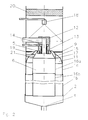
- the device for cleaning Exhaust gases from an outer tube 1 in a vertical arrangement, which is closed at its lower end by a base body 2 is.
- the base body 2 has a conical shape or domed bottom 3, which is at its deepest Place is provided with a drain 4.
- a widening downwards umbrella-like cover 5 arranged a lower Combustion chamber 6 from a washroom 7 located above it departments.
- the cover 5 is held in the outer tube 1 thereby through connecting elements provided with openings 8 9, for example pieces of pipe on which the cover 5 is attached.
- the diameter of the cover 5 smaller than the inner diameter of the outer tube 1. This creates an annular gap 10 in the area of the inner wall of the outer tube 1 kept clear by one the cover 5 attached brush edge 11 is covered.
- the exhaust gas supply nozzle 14 is designed as a central nozzle, that of an annular fuel gas nozzle 13 or more Fuel gas nozzles 13 is surrounded.
- the fuel gas comes here in particular Natural gas into consideration, which with an excess of oxygen is burned, or hydrogen, which also with Excess oxygen is burned.
- the burner 12 is located below the cover 5 or the heat shield surrounding the fuel gas and exhaust gas supply nozzles 13, 14 15, which widens conically downwards and in particular serves to increase the heat load on the cover 5 to reduce.
- the inner tube 16 which extends into the base body, also serves to separate the flame in the combustion chamber 6 from the exhaust gases added in the thermal reaction area, the as reaction gases from the base body 2 on the inside of the outer tube 1 are guided upwards into the washroom 7.
- a spray nozzle 18 for feeding and very fine distribution, or generation of the smallest droplets of a sorbent.
- This sorbent is used to wash out the Burning the exhaust gas resulting gaseous or solid Reaction products.
- the spray cone of the spray nozzle 18 is there designed as a full cone and extends to the inside of the outer tube 1. At the same time cooling in this way of the burner 12 reached.
- the sorbent becomes like an aerosol through the spray nozzle 18 evenly distributed in the washroom 7 and then through the cover 5 and the brush edge 11 attached to it the inside of the outer tube 1 passed and flows from there in the base body 2 and via the drain 4 in one not illustrated container.
- a separator 20 forms the upper end of the washroom 7 for the retention of solid or liquid aerosols with a Exhaust system, not shown, is connected at the same time generates the necessary negative pressure.
- Ignition of the burner flame and to monitor the combustion process extends a bushing 21 from the outside Tube 1 through the cover 5 in the heat shield 15.
- a pilot burner and / or a UV flame sensor can be used to be ordered.
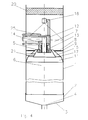
- Fig. 2 basically shows the same device for cleaning of exhaust gases, the outer and inner tubes 1, 16 are divided, so that the device particularly can be easily disassembled or serviced.
- the outer tube 1 consists of an upper and a lower part 1a, 1b and the inner tube 16 from an upper and a lower part 16a, 16b, which are each releasably connected to one another.
- the base body 2 with the outer tube 1 or the lower part la of the outer tube 1 releasably connected be.
- the upper part la of the outer tube 1 with the attached Burner 12, the cover 5, the upper part 16a of the inner Tube 16, the heat shield 15, the openings 8 and the Nozzle ring 19 can also be axially upwards, or the base body 2 axially movable down. This can the combustion chamber 6 can be cleaned particularly easily.
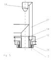
- FIG. 3 shows a special variant of the invention, with an internal exhaust gas recirculation and internal purging of the inner tube 16 is realized.
- the basic structure corresponds to the variant shown in Fig. 2, wherein the upper part 16a of the inner tube 16 at the lower end one Cross-sectional constriction 22 which is concentric with the lower Part 16b is arranged and protrudes into it.
- the circular gap 23 thus formed are parts of the between the lower part 16b and the inside of the lower Part 1b transported exhaust gases up the combustion chamber again 6 fed and exposed again to the hot flame. Furthermore, this return causes the inside to be rinsed of the lower part 16b reached, so that there the deposition of particles is at least partially prevented.
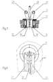
- Fig. 4 shows an embodiment which is not part of the invention in which the combustion chamber 6 is only enclosed by the outer tube 1.
- the supply of the sorbent to the spray nozzle 18 via the burner 12 by inserting the feed line 25 into the housing the burner 12 is guided, as explained below.
- FIG. 5 A particularly effective variant for cooling the burner 12 is apparent from Fig. 5.
- a chamber 26 which surrounds the exhaust gas supply nozzle 14 concentrically.
- This chamber 26 is on the one hand via a line 27 with the spray nozzle 18 and on the other hand with a feed device for rinsing or Sorbent connected. This way one becomes special intensive cooling of the burner is achieved without the temperature the combustion process itself is affected.
- this variant especially for hydrogen burners or for Combustion processes suitable for higher temperatures.
- the number of exhaust gas feeds 29, 29 ' not limited, only the size of the burner 12
- For safe operation with multiple exhaust gas inlets is only a concern to bear that a backflow of the exhaust gas in the exhaust gas inlets 29, 29 'is reliably prevented.
Landscapes
- Engineering & Computer Science (AREA)
- Environmental & Geological Engineering (AREA)
- Chemical & Material Sciences (AREA)
- General Engineering & Computer Science (AREA)
- Mechanical Engineering (AREA)
- Chemical Kinetics & Catalysis (AREA)
- General Chemical & Material Sciences (AREA)
- Oil, Petroleum & Natural Gas (AREA)
- Analytical Chemistry (AREA)
- Biomedical Technology (AREA)
- Health & Medical Sciences (AREA)
- Incineration Of Waste (AREA)
- Treating Waste Gases (AREA)
- Chimneys And Flues (AREA)
- Filtering Of Dispersed Particles In Gases (AREA)
- Electrical Discharge Machining, Electrochemical Machining, And Combined Machining (AREA)
- Processes For Solid Components From Exhaust (AREA)
- Gas Separation By Absorption (AREA)
Claims (21)
- Appareil d'épuration des gaz d'échappement, particulièrement des gaz issus de procédés CVD, de procédés de corrosion plasmatique et similaires, pourvu d'au moins une chambre de combustion (6) disposée verticalement dans un tube externe (1), lequel est limité vers le haut par un couvercle en écran (5), et d'un brûleur (12) à mélange interne ou externe dont les becs (13) dépassent à l'intérieur de la chambre de combustion (6), alimenté en gaz de combustion, en oxygène ou en air et en gaz d'échappement, ainsi que de dispositifs (18) d'amenée et d'évacuation de sorbants ou de sorbants et oxydants dans une chambre d'épuration située au dessus de la chambre de combustion et en plus l'appareil présente les caractéristiques suivantes que le brûleur (12) est fixé au centre du couvercle (5), et le brûleur (12) muni de buses d'alimentation en gaz de combustion (13) et d'au moins une buse d'alimentation en gaz d'échappement (14), dirigées verticalement vers le bas dans la chambre de combustion (6) et la chambre de combustion (6) est limitée vers le bas par un corps de base (2) et dans le tube externe (1), entre le couvercle (5) et le corps de base (2), est placé un tube interne (16) et en plus un espace reste libre entre l'extrémité du tube interne et le fond (3) du corps de base (2) et Le tube interne (16) limite latéralement la chambre de combustion et désormais les produits réactionnels résultant de la combustion sont évacués du corps de base (2) vers le haut dans la chambre d'épuration (7) le long de la paroi intérieure du tube externe (1) et le sorbant, après introduction dans la chambre d'épuration (7) et enrichissement en produits réactionnels, descend le long de la paroi intérieure du tube externe (1) et est évacué par le corps de base (2).
- Appareil selon la spécification 1, caractérisé par la disposition concentrique des buses d'alimentation en gaz de combustion (13) autour des buses d'alimentation en gaz d'échappement (14).
- Appareil selon les spécifications 1 et 2, caractérisé par un brûleur (12) muni d'un dispositif de refroidissement.
- Appareil selon l'une des spécifications 1 à 3, caractérisé par la présence à l'intérieur du tube externe (1) et au dessus du brûleur (12) d'une buse de vaporisation (18) du sorbant ou agent de nettoyage, laquelle se présente soit sous forme de buse annulaire, soit en cône plein ou encore en cône creux.
- Appareil selon la spécification 4, caractérisé par la buse de vaporisation (18) étant reliée par une conduite (27) à une chambre (26) située à l'intérieur du brûleur (12), par laquelle le sorbant ou agent de nettoyage est amené à la buse de vaporisation (18).
- Appareil selon la spécification 5, caractérisé par la disposition concentrique de la chambre (26) entre les buses d'alimentation en gaz de combustion (13) et les buses d'alimentation en gaz d'échappement (14).
- Appareil selon les spécifications 1 à 6, caractérisé par la présence d'un écran thermique (15) entre la chambre de combustion (6) et le couvercle (5), disposé de façon concentrique autour du brûleur (12) et s'élargissant vers le bas.
- Appareil selon les spécifications 1 à 7, caractérisé par le tube interne (16) encerclant l'écran thermique (15).
- Appareil selon la spécification 8, caractérisé par la présence d'un passage annulaire (17) entre l'écran thermique (15) et la paroi intérieure du tube interne (16), et par la présence d'ouvertures (8) reliant l'espace compris entre le couvercle (5) et l'écran thermique (15) à l'espace situé en dehors du tube externe (1).
- Appareil selon l'une des spécifications 7 à 9 caractérisé par la présence d'une couronne directrice (19) dans l'espace compris entre le couvercle (5) et l'écran thermique (15), laquelle est pourvue de buses d'alimentation en agent de nettoyage dirigées contre la paroi intérieure du tube interne (16).
- Appareil selon l'une des spécifications 1 à 10, caractérisé par la présence d'une vidange au point le plus bas du fond (3) du corps de base (2).
- Appareil selon l'une des spécifications 1 à 12, caractérisé par les tubes externe et interne (1, 16) se composant chacun d'une partie supérieure et inférieure (1a, 16a; 1b, 16b), chaque partie étant amovible.
- Appareil selon la spécification 12, caractérisé par le corps de base (2) pouvant se détacher du tube externe (1) ou de la partie (1b) du tube externe (1).
- Appareil selon les spécifications 12 et 13, caractérisé par le permettant un déplacement axial vers le haut de la partie supérieure (1a) du tube externe (1), du couvercle (5) brûleur (1) compris, de la partie supérieure (16a) du tube interne (16), de l'écran thermique (15) des ouvertures (8) et de la couronne directrice (19).
- Appareil selon les spécifications 12 et 13, caractérisé par le permettant un déplacement axial vers le bas du corps de base (2).
- Appareil selon les spécifications 12 à 14, caractérisé par une réduction de section (22) de la partie supérieure (16a) du tube interne (16), laquelle forme un passage en couronne (23) avec l'extrémité supérieure de la partie inférieure (16b).
- Appareil selon la spécification 16, caractérisé par la présence d'un tube protecteur (24) entre la partie supérieure (1a) du tube externe (16) et la partie supérieure du tube interne, lequel recouvre le bord supérieur de la partie inférieure (16b).
- Appareil selon les spécifications 1 à 17, caractérisé par la présence de traversées (21) reliant la chambre de combustion (6) à l'espace en dehors du tube (1) et dans les traversées (21) sont placés des dispositifs d'allumage ou de surveillance du brûleur (12).
- Appareil selon les spécifications 1 à 18, caractérisé par le brûleur lui-même (12) étant pourvu de dispositifs d'allumage ou de surveillance.
- Appareil selon les spécifications 1 à 19, caractérisé par la présence de brosses (11) entre le couvercle (5) et la paroi intérieure du tube externe (1).
- Appareil selon les spécifications 1 à 20, caractérisé par le raccordement, au moyen de un ou plusieurs séparateurs (20), du tube externe (1) au dessus du couvercle (5) à une installation aéraulique servant à provoquer une dépression dans la chambre de combustion (6) et la chambre d'épuration (7).
Applications Claiming Priority (3)
| Application Number | Priority Date | Filing Date | Title |
|---|---|---|---|
| DE19501914 | 1995-01-23 | ||
| DE19501914A DE19501914C1 (de) | 1995-01-23 | 1995-01-23 | Vorrichtung zur Reinigung von Abgasen |
| PCT/DE1996/000076 WO1996023173A1 (fr) | 1995-01-23 | 1996-01-19 | Dispositif pour epurer des gaz brules |
Publications (2)
| Publication Number | Publication Date |
|---|---|
| EP0803042A1 EP0803042A1 (fr) | 1997-10-29 |
| EP0803042B1 true EP0803042B1 (fr) | 1998-08-19 |
Family
ID=7752085
Family Applications (1)
| Application Number | Title | Priority Date | Filing Date |
|---|---|---|---|
| EP96900836A Expired - Lifetime EP0803042B1 (fr) | 1995-01-23 | 1996-01-19 | Dispositif pour epurer des gaz brules |
Country Status (10)
| Country | Link |
|---|---|
| US (1) | US5900217A (fr) |
| EP (1) | EP0803042B1 (fr) |
| JP (1) | JP3111080B2 (fr) |
| KR (1) | KR100421814B1 (fr) |
| AT (1) | ATE169994T1 (fr) |
| AU (1) | AU4480896A (fr) |
| DE (2) | DE19501914C1 (fr) |
| FI (1) | FI973084A7 (fr) |
| RU (1) | RU2158391C2 (fr) |
| WO (1) | WO1996023173A1 (fr) |
Cited By (2)
| Publication number | Priority date | Publication date | Assignee | Title |
|---|---|---|---|---|
| WO2006034684A1 (fr) * | 2004-09-28 | 2006-04-06 | Centrotherm Clean Solutions Gmbh + Co. Kg | Ensemble pour epurer des gaz toxiques de processus de production |
| CN108437294A (zh) * | 2018-04-24 | 2018-08-24 | 德昌金锋橡胶有限公司 | 一种充分分解废旧轮胎的工艺 |
Families Citing this family (26)
| Publication number | Priority date | Publication date | Assignee | Title |
|---|---|---|---|---|
| US5955037A (en) * | 1996-12-31 | 1999-09-21 | Atmi Ecosys Corporation | Effluent gas stream treatment system having utility for oxidation treatment of semiconductor manufacturing effluent gases |
| DE29712026U1 (de) | 1997-07-09 | 1998-11-12 | EBARA Germany GmbH, 63452 Hanau | Brenner für die Verbrennung von Abgasen mit mindestens einer kondensationsfähigen Komponente |
| US6153150A (en) * | 1998-01-12 | 2000-11-28 | Advanced Technology Materials, Inc. | Apparatus and method for controlled decomposition oxidation of gaseous pollutants |
| US6261524B1 (en) * | 1999-01-12 | 2001-07-17 | Advanced Technology Materials, Inc. | Advanced apparatus for abatement of gaseous pollutants |
| CN1141167C (zh) * | 1998-05-29 | 2004-03-10 | 森托塞姆投资两合公司 | 工业废气净化方法 |
| DE19927540A1 (de) | 1999-06-16 | 2000-12-21 | Ct Therm Elek Sche Anlagen Gmb | Abgasreinigungssystem |
| US6423284B1 (en) * | 1999-10-18 | 2002-07-23 | Advanced Technology Materials, Inc. | Fluorine abatement using steam injection in oxidation treatment of semiconductor manufacturing effluent gases |
| US6736635B1 (en) | 1999-11-02 | 2004-05-18 | Ebara Corporation | Combustor for exhaust gas treatment |
| TW542886B (en) * | 2000-08-22 | 2003-07-21 | Ebara Corp | Method and device for combustion type exhaust gas treatment |
| DE10342692B4 (de) * | 2003-09-09 | 2006-01-12 | DAS-Dünnschicht Anlagen Systeme GmbH Dresden | Vorrichtung zur thermischen Behandlung von Schadstoffe enthaltenden Prozessabgasen |
| DE10355970A1 (de) * | 2003-11-24 | 2005-06-23 | DAS-Dünnschicht Anlagen Systeme GmbH Dresden | Vorrichtung und Verfahren für die Separation von Partikeln aus thermisch nachbehandelten Prozessabgasen |
| US7569193B2 (en) | 2003-12-19 | 2009-08-04 | Applied Materials, Inc. | Apparatus and method for controlled combustion of gaseous pollutants |
| US7736599B2 (en) * | 2004-11-12 | 2010-06-15 | Applied Materials, Inc. | Reactor design to reduce particle deposition during process abatement |
| SE0501840L (sv) * | 2005-08-19 | 2007-02-20 | Aga Ab | Förfarande jämte för övervakning av en brännare |
| CN101300411B (zh) * | 2005-10-31 | 2012-10-03 | 应用材料公司 | 制程减降反应器 |
| KR100650937B1 (ko) * | 2005-11-09 | 2006-11-29 | 주식회사 글로벌스탠다드테크놀로지 | 폐가스 정화처리장치의 버너조립체 |
| KR100634173B1 (ko) * | 2006-06-23 | 2006-10-16 | 주식회사 이즈컨텍 | 폐가스 처리장치 |
| JP2009174740A (ja) * | 2008-01-22 | 2009-08-06 | Fine Energy Kk | 廃棄物処理方法及び装置 |
| US9089811B2 (en) * | 2012-04-30 | 2015-07-28 | Highvac Corp. | Coaxial / coaxial treatment module |
| GB2516267B (en) * | 2013-07-17 | 2016-08-17 | Edwards Ltd | Head assembly |
| CN103830994B (zh) * | 2013-12-05 | 2016-03-02 | 山东派力迪环保工程有限公司 | 一种排级式等离子体裂解氧化反应器 |
| CN107246616B (zh) * | 2017-06-09 | 2018-12-18 | 加拿大艾浦莱斯有限公司 | 一种等离子体催化合成气燃烧室 |
| NL2032864B1 (en) * | 2022-08-26 | 2024-03-05 | Levitech B V | An exhaust abatement apparatus and a method for abating reactive gasses |
| KR20250149991A (ko) | 2023-02-17 | 2025-10-17 | 파이퍼 팝 솔루션즈 게엠베하 | 환경적으로 해로운 및/또는 독성을 갖는 배기 가스를 처리하고 중화하기 위한 방법 및 장치 |
| US20250149314A1 (en) * | 2023-11-03 | 2025-05-08 | Samsung Electronics Co., Ltd. | Scrubber, substrate processing system including the same, and substrate processing method using the same |
| DE102024132019A1 (de) | 2024-11-04 | 2026-05-07 | Pfeiffer FAB Solutions GmbH | Verfahren zur Behandlung von Abgasbestandteilen und Abgasbehandlungssystem |
Family Cites Families (8)
| Publication number | Priority date | Publication date | Assignee | Title |
|---|---|---|---|---|
| US4555389A (en) * | 1984-04-27 | 1985-11-26 | Toyo Sanso Co., Ltd. | Method of and apparatus for burning exhaust gases containing gaseous silane |
| SU1395901A1 (ru) * | 1986-06-18 | 1988-05-15 | Предприятие П/Я В-8796 | Устройство дл дожигани отбросных газов |
| DE3731205A1 (de) * | 1987-09-17 | 1989-03-30 | Erdoelchemie Gmbh | Vorrichtung zum eintrag von gasen in brennraeume sowie verfahren zur minderung von schadstoffen bei verbrennungsvorgaengen |
| DD273009A1 (de) * | 1988-06-15 | 1989-11-01 | Elektromat Veb | Verfahren zur reinigung von abgasen aus cvd-prozessen |
| DD273008A1 (de) * | 1988-06-15 | 1989-11-01 | Elektromat Veb | Vorrichtung zum reinigen von abgasen aus niederdruckprozessen |
| US5123836A (en) * | 1988-07-29 | 1992-06-23 | Chiyoda Corporation | Method for the combustion treatment of toxic gas-containing waste gas |
| DE4320044A1 (de) * | 1993-06-17 | 1994-12-22 | Das Duennschicht Anlagen Sys | Verfahren und Einrichtung zur Reinigung von Abgasen |
| DE19600873A1 (de) * | 1996-01-12 | 1997-10-02 | Das Duennschicht Anlagen Sys | Verfahren und Einrichtung zur Reinigung von schadstoffhaltigen Abgasen durch Verbrennen und chemische Umsetzung mit Hilfe einer Flamme in einer Brennkammer |
-
1995
- 1995-01-23 DE DE19501914A patent/DE19501914C1/de not_active Expired - Fee Related
-
1996
- 1996-01-19 US US08/875,312 patent/US5900217A/en not_active Expired - Lifetime
- 1996-01-19 AT AT96900836T patent/ATE169994T1/de active
- 1996-01-19 DE DE59600454T patent/DE59600454D1/de not_active Expired - Fee Related
- 1996-01-19 AU AU44808/96A patent/AU4480896A/en not_active Abandoned
- 1996-01-19 JP JP08522542A patent/JP3111080B2/ja not_active Expired - Fee Related
- 1996-01-19 EP EP96900836A patent/EP0803042B1/fr not_active Expired - Lifetime
- 1996-01-19 WO PCT/DE1996/000076 patent/WO1996023173A1/fr not_active Ceased
- 1996-01-19 KR KR1019970704967A patent/KR100421814B1/ko not_active Expired - Fee Related
- 1996-01-19 RU RU97114190/03A patent/RU2158391C2/ru active
-
1997
- 1997-07-22 FI FI973084A patent/FI973084A7/fi unknown
Cited By (3)
| Publication number | Priority date | Publication date | Assignee | Title |
|---|---|---|---|---|
| WO2006034684A1 (fr) * | 2004-09-28 | 2006-04-06 | Centrotherm Clean Solutions Gmbh + Co. Kg | Ensemble pour epurer des gaz toxiques de processus de production |
| CN101031349B (zh) * | 2004-09-28 | 2011-01-19 | 森特罗瑟清洁方案商业有限两合公司 | 用于清洁生产过程中产生的有毒气体的装置 |
| CN108437294A (zh) * | 2018-04-24 | 2018-08-24 | 德昌金锋橡胶有限公司 | 一种充分分解废旧轮胎的工艺 |
Also Published As
| Publication number | Publication date |
|---|---|
| WO1996023173A1 (fr) | 1996-08-01 |
| JP3111080B2 (ja) | 2000-11-20 |
| EP0803042A1 (fr) | 1997-10-29 |
| KR19980701575A (ko) | 1998-05-15 |
| KR100421814B1 (ko) | 2004-04-21 |
| FI973084A0 (fi) | 1997-07-22 |
| FI973084A7 (fi) | 1997-09-23 |
| DE19501914C1 (de) | 1996-04-04 |
| DE59600454D1 (de) | 1998-09-24 |
| RU2158391C2 (ru) | 2000-10-27 |
| US5900217A (en) | 1999-05-04 |
| AU4480896A (en) | 1996-08-14 |
| ATE169994T1 (de) | 1998-09-15 |
| JPH10510914A (ja) | 1998-10-20 |
Similar Documents
| Publication | Publication Date | Title |
|---|---|---|
| EP0803042B1 (fr) | Dispositif pour epurer des gaz brules | |
| EP1796820B1 (fr) | Ensemble pour epurer des gaz toxiques de procedes de production | |
| EP0438682B1 (fr) | Système d'échappement avec filtre à particules et brûleur de régénération | |
| DE19802404B4 (de) | Vorrichtung zur Gasreinigung sowie Verfahren zur Behandlung eines zu reinigenden Gases | |
| DE60212546T2 (de) | Gaswäscher zur Entfernung von Feststoffpartikeln von Abgasen | |
| DD227980A1 (de) | Apparat fuer die vergasung von kohlenstaub | |
| EP0429942B1 (fr) | Appareil pour l'échange d'une matière entre un courant gazeux chaud et un liquide | |
| EP0346893B1 (fr) | Dispositif pour purifier des gaz d'échappement d'un procédé CVD | |
| DE10304489A1 (de) | Einrichtung zur Reinigung von Abgasen mit fluorhaltigen Verbindungen in einem Verbrennungsreaktor mit niedriger Stickoxidemission | |
| DE3242226A1 (de) | Oeffnungsanordnung zur gaseinleitung mit teilchensperre | |
| EP0347753A1 (fr) | Procédé pour la purification de gaz d'échappement | |
| DE2502694A1 (de) | Vorrichtung und verfahren zur ueberwachung der verunreinigung von daempfen oder gasen | |
| WO2003085321A1 (fr) | Dispositif de purification de gaz d'echappement renfermant des composes contenant du fluor dans un reacteur de combustion | |
| DE10140422C1 (de) | Thermische Nachverbrennungsvorrichtung | |
| DE10342498B4 (de) | Verfahren und Vorrichtung für die thermische Abgasreinigung | |
| DE2419085A1 (de) | Vorrichtung zum verbrennen von abfall | |
| DE3105099A1 (de) | Verbrennungsvorrichtung | |
| EP1108186B1 (fr) | Procede et dispositif pour la purification d'effluents gazeux par postcombustion thermique | |
| DE2300389C3 (de) | Verbrennungsofen zum Verbrennen flußiger Abfalle | |
| EP4437273B1 (fr) | Procédé et dispositif de traitement et de neutralisation d'effluents gazeux nocifs pour l'environnement et/ou toxiques | |
| WO1993000148A1 (fr) | Dispositif de nettoyage par voie humide, notamment pour separer des impuretes gazeuses, liquides et/ou solides contenues dans des courants gazeux | |
| DE2508810C2 (de) | Verbrennungsofen für gasförmige, flüssige bzw. aufgeschlämmte feste Abfälle | |
| DE3434866C2 (de) | Tauchkühler zum Kühlen und Waschen von strömenden staubbeladenen, heißen Gasen | |
| DE3717375A1 (de) | Einrichtung fuer die reinigung von ventilationsausscheidungen | |
| DE1596326C (de) | Vorrichtung zum Kühlen und Reinigen von Gasen |
Legal Events
| Date | Code | Title | Description |
|---|---|---|---|
| PUAI | Public reference made under article 153(3) epc to a published international application that has entered the european phase |
Free format text: ORIGINAL CODE: 0009012 |
|
| 17P | Request for examination filed |
Effective date: 19970701 |
|
| AK | Designated contracting states |
Kind code of ref document: A1 Designated state(s): AT BE CH DE FR GB IE LI NL |
|
| GRAG | Despatch of communication of intention to grant |
Free format text: ORIGINAL CODE: EPIDOS AGRA |
|
| GRAG | Despatch of communication of intention to grant |
Free format text: ORIGINAL CODE: EPIDOS AGRA |
|
| GRAG | Despatch of communication of intention to grant |
Free format text: ORIGINAL CODE: EPIDOS AGRA |
|
| GRAH | Despatch of communication of intention to grant a patent |
Free format text: ORIGINAL CODE: EPIDOS IGRA |
|
| 17Q | First examination report despatched |
Effective date: 19980123 |
|
| GRAH | Despatch of communication of intention to grant a patent |
Free format text: ORIGINAL CODE: EPIDOS IGRA |
|
| GRAA | (expected) grant |
Free format text: ORIGINAL CODE: 0009210 |
|
| AK | Designated contracting states |
Kind code of ref document: B1 Designated state(s): AT BE CH DE FR GB IE LI NL |
|
| REF | Corresponds to: |
Ref document number: 169994 Country of ref document: AT Date of ref document: 19980915 Kind code of ref document: T |
|
| REG | Reference to a national code |
Ref country code: CH Ref legal event code: EP |
|
| REF | Corresponds to: |
Ref document number: 59600454 Country of ref document: DE Date of ref document: 19980924 |
|
| REG | Reference to a national code |
Ref country code: IE Ref legal event code: FG4D Free format text: GERMAN |
|
| GBT | Gb: translation of ep patent filed (gb section 77(6)(a)/1977) |
Effective date: 19981113 |
|
| REG | Reference to a national code |
Ref country code: CH Ref legal event code: NV Representative=s name: ARNOLD & SIEDSMA AG |
|
| ET | Fr: translation filed | ||
| NLR4 | Nl: receipt of corrected translation in the netherlands language at the initiative of the proprietor of the patent | ||
| PG25 | Lapsed in a contracting state [announced via postgrant information from national office to epo] |
Ref country code: IE Free format text: LAPSE BECAUSE OF NON-PAYMENT OF DUE FEES Effective date: 19990504 |
|
| PLBE | No opposition filed within time limit |
Free format text: ORIGINAL CODE: 0009261 |
|
| STAA | Information on the status of an ep patent application or granted ep patent |
Free format text: STATUS: NO OPPOSITION FILED WITHIN TIME LIMIT |
|
| REG | Reference to a national code |
Ref country code: IE Ref legal event code: FD4D |
|
| 26N | No opposition filed | ||
| PG25 | Lapsed in a contracting state [announced via postgrant information from national office to epo] |
Ref country code: DE Free format text: LAPSE BECAUSE OF NON-PAYMENT OF DUE FEES Effective date: 19991103 |
|
| PGFP | Annual fee paid to national office [announced via postgrant information from national office to epo] |
Ref country code: NL Payment date: 20011220 Year of fee payment: 7 |
|
| REG | Reference to a national code |
Ref country code: GB Ref legal event code: IF02 |
|
| PGFP | Annual fee paid to national office [announced via postgrant information from national office to epo] |
Ref country code: CH Payment date: 20020124 Year of fee payment: 7 |
|
| PGFP | Annual fee paid to national office [announced via postgrant information from national office to epo] |
Ref country code: BE Payment date: 20020125 Year of fee payment: 7 |
|
| PG25 | Lapsed in a contracting state [announced via postgrant information from national office to epo] |
Ref country code: LI Free format text: LAPSE BECAUSE OF NON-PAYMENT OF DUE FEES Effective date: 20030131 Ref country code: CH Free format text: LAPSE BECAUSE OF NON-PAYMENT OF DUE FEES Effective date: 20030131 Ref country code: BE Free format text: LAPSE BECAUSE OF NON-PAYMENT OF DUE FEES Effective date: 20030131 |
|
| PG25 | Lapsed in a contracting state [announced via postgrant information from national office to epo] |
Ref country code: NL Free format text: LAPSE BECAUSE OF NON-PAYMENT OF DUE FEES Effective date: 20030801 |
|
| REG | Reference to a national code |
Ref country code: CH Ref legal event code: PL |
|
| NLV4 | Nl: lapsed or anulled due to non-payment of the annual fee |
Effective date: 20030801 |
|
| REG | Reference to a national code |
Ref country code: GB Ref legal event code: 732E |
|
| REG | Reference to a national code |
Ref country code: FR Ref legal event code: TP |
|
| PGFP | Annual fee paid to national office [announced via postgrant information from national office to epo] |
Ref country code: FR Payment date: 20110201 Year of fee payment: 16 Ref country code: AT Payment date: 20110120 Year of fee payment: 16 |
|
| PGFP | Annual fee paid to national office [announced via postgrant information from national office to epo] |
Ref country code: GB Payment date: 20110121 Year of fee payment: 16 |
|
| GBPC | Gb: european patent ceased through non-payment of renewal fee |
Effective date: 20120119 |
|
| REG | Reference to a national code |
Ref country code: FR Ref legal event code: ST Effective date: 20120928 |
|
| PG25 | Lapsed in a contracting state [announced via postgrant information from national office to epo] |
Ref country code: GB Free format text: LAPSE BECAUSE OF NON-PAYMENT OF DUE FEES Effective date: 20120119 |
|
| REG | Reference to a national code |
Ref country code: AT Ref legal event code: MM01 Ref document number: 169994 Country of ref document: AT Kind code of ref document: T Effective date: 20120119 |
|
| PG25 | Lapsed in a contracting state [announced via postgrant information from national office to epo] |
Ref country code: FR Free format text: LAPSE BECAUSE OF NON-PAYMENT OF DUE FEES Effective date: 20120131 |
|
| PG25 | Lapsed in a contracting state [announced via postgrant information from national office to epo] |
Ref country code: AT Free format text: LAPSE BECAUSE OF NON-PAYMENT OF DUE FEES Effective date: 20120119 |