EP0803285A2 - Process and device for effecting the transition from a continuous to a discontinuous process stage - Google Patents
Process and device for effecting the transition from a continuous to a discontinuous process stage Download PDFInfo
- Publication number
- EP0803285A2 EP0803285A2 EP97105991A EP97105991A EP0803285A2 EP 0803285 A2 EP0803285 A2 EP 0803285A2 EP 97105991 A EP97105991 A EP 97105991A EP 97105991 A EP97105991 A EP 97105991A EP 0803285 A2 EP0803285 A2 EP 0803285A2
- Authority
- EP
- European Patent Office
- Prior art keywords
- continuous
- discontinuous
- process stage
- continuous process
- stage
- Prior art date
- Legal status (The legal status is an assumption and is not a legal conclusion. Google has not performed a legal analysis and makes no representation as to the accuracy of the status listed.)
- Withdrawn
Links
- 238000000034 method Methods 0.000 title claims abstract description 30
- 230000007704 transition Effects 0.000 title 1
- 238000010924 continuous production Methods 0.000 claims abstract description 23
- 238000009825 accumulation Methods 0.000 claims description 7
- 238000010327 methods by industry Methods 0.000 claims description 5
- 239000007787 solid Substances 0.000 claims description 4
- 239000008187 granular material Substances 0.000 claims description 3
- 238000001816 cooling Methods 0.000 description 6
- 239000000725 suspension Substances 0.000 description 4
- 230000008020 evaporation Effects 0.000 description 3
- 238000001704 evaporation Methods 0.000 description 3
- 238000004519 manufacturing process Methods 0.000 description 2
- 238000003860 storage Methods 0.000 description 2
- 239000013590 bulk material Substances 0.000 description 1
- 238000002425 crystallisation Methods 0.000 description 1
- 230000008025 crystallization Effects 0.000 description 1
- 238000011143 downstream manufacturing Methods 0.000 description 1
- 238000012432 intermediate storage Methods 0.000 description 1
- 239000000463 material Substances 0.000 description 1
- 239000002904 solvent Substances 0.000 description 1
- 238000001228 spectrum Methods 0.000 description 1
- 239000000126 substance Substances 0.000 description 1
Images
Classifications
-
- B—PERFORMING OPERATIONS; TRANSPORTING
- B01—PHYSICAL OR CHEMICAL PROCESSES OR APPARATUS IN GENERAL
- B01J—CHEMICAL OR PHYSICAL PROCESSES, e.g. CATALYSIS OR COLLOID CHEMISTRY; THEIR RELEVANT APPARATUS
- B01J4/00—Feed or outlet devices; Feed or outlet control devices
- B01J4/008—Feed or outlet control devices
-
- B—PERFORMING OPERATIONS; TRANSPORTING
- B01—PHYSICAL OR CHEMICAL PROCESSES OR APPARATUS IN GENERAL
- B01J—CHEMICAL OR PHYSICAL PROCESSES, e.g. CATALYSIS OR COLLOID CHEMISTRY; THEIR RELEVANT APPARATUS
- B01J19/00—Chemical, physical or physico-chemical processes in general; Their relevant apparatus
- B01J19/18—Stationary reactors having moving elements inside
-
- B—PERFORMING OPERATIONS; TRANSPORTING
- B01—PHYSICAL OR CHEMICAL PROCESSES OR APPARATUS IN GENERAL
- B01J—CHEMICAL OR PHYSICAL PROCESSES, e.g. CATALYSIS OR COLLOID CHEMISTRY; THEIR RELEVANT APPARATUS
- B01J19/00—Chemical, physical or physico-chemical processes in general; Their relevant apparatus
- B01J19/18—Stationary reactors having moving elements inside
- B01J19/20—Stationary reactors having moving elements inside in the form of helices, e.g. screw reactors
-
- B—PERFORMING OPERATIONS; TRANSPORTING
- B01—PHYSICAL OR CHEMICAL PROCESSES OR APPARATUS IN GENERAL
- B01J—CHEMICAL OR PHYSICAL PROCESSES, e.g. CATALYSIS OR COLLOID CHEMISTRY; THEIR RELEVANT APPARATUS
- B01J2219/00—Chemical, physical or physico-chemical processes in general; Their relevant apparatus
- B01J2219/00049—Controlling or regulating processes
- B01J2219/00164—Controlling or regulating processes controlling the flow
Definitions
- discontinuous process step can only be implemented as a continuous process step with great technical effort, e.g. if a material flow of solid granular material has to be conveyed between process stages in which there is different gas pressure or the downstream process step requires a very narrow residence time spectrum, e.g. may be the case in the production of polymeric molecules of the same molecular weight or crystallization processes.
- a continuous process stage is linked to a downstream discontinuous process stage via an intermediate buffer vessel into which the continuous stage is continuously conveyed and from which the discontinuous process stage is fed in batches.
- a buffer vessel is particularly technically complex if certain process engineering conditions such as temperature, atmosphere or movement have to be maintained for the product stream to be buffered.
- the object of the present invention is to link a continuous process stage with a downstream discontinuous process stage without an intermediate buffer vessel.
- the object is achieved in that the product discharge from the continuous process stage is interrupted at intervals by means of a damming device.
- the process according to the invention is particularly suitable for continuous process stages which are carried out in large-volume, only partially filled reactors such as screw machines or stirred tanks.
- the process according to the invention can be used particularly advantageously if the residence time in the continuous process stage is a multiple of the residence time in the discontinuous process stage.
- the batch of the discontinuous process stage should preferably be less than 20%, in particular less than 15%, of the filling volume of the continuous process stage, so that the dwell time in the continuous process stage is influenced only to a reasonable extent by the accumulation.
- the required dwell time in the downstream discontinuous stage is greater than the permissible dwell time fluctuation in the continuous stage, this can be taken into account by connecting two or more discontinuous stages to the continuous stage, the interval frequency of the damming device being correspondingly doubled or multiplied. Furthermore, it is possible to provide a separate accumulation device for each subsequent discontinuous process stage, the accumulation devices working out of phase.
- Valves in particular slide or piston valves, are suitable as accumulation devices, each of which is opened at intervals to fill the discontinuous process stage. While the accumulation device is closed, the continuous process stage is fed continuously, so that the degree of filling of the continuous stage increases approximately by the batch volume of the discontinuous stage.
- the product is preferably removed from the continuous stage by means of an overflow, the lower level of which corresponds approximately to the lower filling level of the continuous stage.
- the overflow is closed or opened at intervals by means of the storage device.
- the product of the continuous process step is a (preferably) solid granular material
- pressure equalization via the accumulation device between the continuous process stage and the feed line to the discontinuous process stage is advantageous.
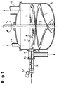
- the continuous process stage shown as an example consists of a container 1 in which there is a stirrer 3 which is driven through the wall and is driven via the stirrer axis 2.
- the continuous process stage is used to evaporate solutions and / or suspensions to dry matter.
- the solution and / or suspension to be evaporated is continuously conveyed into the container 1 via the feed pipe 4.
- a bed of granular solid mass 5, which can preferably consist of previously generated dry mass, is kept in the container at a temperature above the evaporation temperature of the solution and / or suspension.
- the container 1 also has a steam exhaust pipe 6, via which the evaporated solvent or suspension medium is drawn off.
- a pressure of 10 to 100 mbar prevails in the gas space above the stirred dry mass 5.
- an overflow pipe 7 is arranged, through which the dry mass produced by evaporation is discharged and, for example, fed to a stirred cooling container which is operated under normal pressure.
- the cooling container has valves on the inlet and outlet sides and is operated discontinuously.
- the overflow pipe 7 can be closed at intervals by means of a storage device.
- a stowage device is shown as an example, which is formed from a stowage piston 8 movable in the direction of the axis 9 by means of the drive device 10.
- the piston 8 is in the closing function (as shown)
- the filling level of the stirred bed rises from the filling level A to the filling level B.
- the piston 8 is moved back to the position 8a, the filling level of the stirred container 1 drops very quickly from the filling level B to the filling level A.
- the dry matter emerging through the overflow pipe 7 is filled directly into the discontinuously operated cooling container without intermediate storage.
- the piston 8 is moved back into the stowed position, the inlet valve of the cooling container is closed, the cooling container is vented. After the dry matter has cooled, the outlet valve of the cooling container is opened and the cooled batch is emptied.
Landscapes
- Chemical & Material Sciences (AREA)
- Organic Chemistry (AREA)
- Chemical Kinetics & Catalysis (AREA)
- Basic Packing Technique (AREA)
- Air Transport Of Granular Materials (AREA)
- Stacking Of Articles And Auxiliary Devices (AREA)
- Container Filling Or Packaging Operations (AREA)
- Feeding, Discharge, Calcimining, Fusing, And Gas-Generation Devices (AREA)
- Physical Or Chemical Processes And Apparatus (AREA)
- Filling Or Emptying Of Bunkers, Hoppers, And Tanks (AREA)
- Inorganic Insulating Materials (AREA)
- Auxiliary Devices For And Details Of Packaging Control (AREA)
- Luminescent Compositions (AREA)
Abstract
Es werden ein Verfahren und eine Vorrichtung beschrieben bestehend aus einer kontinuierlichen Prozeßstufe und einer nachgeschalteten diskontinuierlichen Prozeßstufe, wobei der Produktauslaß der kontinuierlichen Prozeßstufe mit einer intervallweise betriebenen Stauvorrichtung versehen ist, so daß auf ein Zwischenpuffergefäß verzichtet werden kann.
Description
Zur wirtschaftlichen Herstellung von Produkten der chemischen, pharmazeutischen oder Lebensmittelindustrie ist es erforderlich, eine möglichst unterbrechungsfreie Prozeßkette zu realisieren. Laufen die einzelnen Prozeßstufen dabei kontinuierlich ab, können diese direkt miteinander gekoppelt werden. Dies wird in der Regel angestrebt.For the economical production of products in the chemical, pharmaceutical or food industry, it is necessary to implement a process chain that is as uninterrupted as possible. If the individual process stages run continuously, they can be linked directly to one another. This is usually the goal.
Vielfach ergibt sich jedoch die Notwendigkeit, kontinuierliche Prozeßschritte mit diskontinuierlichen, d.h. chargenweisen, Prozeßschritten zu verbinden. Dies ist regelmäßig dann der Fall, wenn sich der diskontinuierliche Prozeßschritt nur mit hohem technischem Aufwand als kontinuierlicher Prozeßschritt realisieren läßt, z.B. wenn ein Stoffstrom aus festem körnigem Material zwischen Prozeßstufen, in denen unterschiedlicher Gasdruck herrscht, zu fördern ist oder der nachgeschaltete Prozeßschritt ein sehr enges Verweilzeitspektrum erfordert, wie das z.B. bei der Herstellung von polymeren Molekülen gleichen Molekulargewichtes oder Kristallisationsprozessen der Fall sein kann.In many cases, however, there is a need for continuous process steps with discontinuous, i.e. batch-wise to combine process steps. This is regularly the case if the discontinuous process step can only be implemented as a continuous process step with great technical effort, e.g. if a material flow of solid granular material has to be conveyed between process stages in which there is different gas pressure or the downstream process step requires a very narrow residence time spectrum, e.g. may be the case in the production of polymeric molecules of the same molecular weight or crystallization processes.
Üblicherweise erfolgt die Verknüpfung einer kontinuierlichen Prozeßstufe mit einer nachgeschalteten diskontinuierlichen Prozeßstufe über ein Zwischenpuffergefäß, in das aus der kontinuierlichen Stufe kontinuierlich gefördert wird und aus dem die diskontinuierliche Prozeßstufe chargenweise beschickt wird. Ein solches Puffergefäß ist insbesondere dann technisch aufwendig, wenn für den zu puffernden Produktstrom bestimmte verfahrenstechnische Bedingungen wie Temperatur, Atmosphäre oder Bewegung aufrechtzuerhalten sind.Usually, a continuous process stage is linked to a downstream discontinuous process stage via an intermediate buffer vessel into which the continuous stage is continuously conveyed and from which the discontinuous process stage is fed in batches. Such a buffer vessel is particularly technically complex if certain process engineering conditions such as temperature, atmosphere or movement have to be maintained for the product stream to be buffered.
Aufgabe der vorliegenden Erfindung ist es, eine kontinuierliche Prozeßstufe mit einer nachgeschalteten diskontinuierlichen Prozeßstufe ohne ein zwischengeschaltetes Puffergefäß verfahrenstechnisch zu verknüpfen.The object of the present invention is to link a continuous process stage with a downstream discontinuous process stage without an intermediate buffer vessel.
Die Aufgabe wird dadurch gelöst, daß der Produktaustritt aus der kontinuierlichen Prozeßstufe intervallweise mittels einer Stauvorrichtung unterbrochen wird.The object is achieved in that the product discharge from the continuous process stage is interrupted at intervals by means of a damming device.
Das erfindungsgemäße Verfahren ist insbesondere für kontinuierliche Prozeßstufen geeignet, die in großvolumigen, nur teilweise gefüllten Reaktoren durchgeführt werden, wie z.B. Schneckenmaschinen oder Rührbehältern. Insbesondere vorteilhaft kann das erfindungsgemäße Verfahren dann eingesetzt werden, wenn die Verweilzeit in der kontinuierlichen Prozeßstufe ein mehrfaches der Verweilzeit in der diskontinuierlichen Prozeßstufe beträgt. Bevorzugt soll die Charge der diskontinuierlichen Prozeßstufe weniger als 20 %, insbesondere weniger als 15 %, des Füllvolumens der kontinuierlichen Prozeßstufe betragen, so daß die Verweilzeit in der kontinuierlichen Prozeßstufe durch das Anstauen nur in vertretbarem Rahmen beeinflußt wird.The process according to the invention is particularly suitable for continuous process stages which are carried out in large-volume, only partially filled reactors such as screw machines or stirred tanks. The process according to the invention can be used particularly advantageously if the residence time in the continuous process stage is a multiple of the residence time in the discontinuous process stage. The batch of the discontinuous process stage should preferably be less than 20%, in particular less than 15%, of the filling volume of the continuous process stage, so that the dwell time in the continuous process stage is influenced only to a reasonable extent by the accumulation.
Ist die erforderliche Verweilzeit in der nachgeschalteten diskontinuierlichen Stufe größer als die zulässige Verweilzeitschwankung in der kontinuierlichen Stufe, kann dem dadurch Rechnung getragen werden, daß zwei oder mehr diskontinuierliche Stufen der kontinuierlichen Stufe nachgeschaltet werden, wobei die Intervallfrequenz der Stauvorrichtung entsprechend verdoppelt bzw. vervielfacht wird. Ferner ist es möglich, für jede nachgeschaltete diskontinuierliche Prozeßstufe eine getrennte Stauvorrichtung vorzusehen, wobei die Stauvorrichtungen phasenverschoben arbeiten.If the required dwell time in the downstream discontinuous stage is greater than the permissible dwell time fluctuation in the continuous stage, this can be taken into account by connecting two or more discontinuous stages to the continuous stage, the interval frequency of the damming device being correspondingly doubled or multiplied. Furthermore, it is possible to provide a separate accumulation device for each subsequent discontinuous process stage, the accumulation devices working out of phase.
Als Stauvorrichtungen sind Ventile, insbesondere Schieber bzw. Kolbenventile geeignet, die jeweils intervallweise zur Befüllung der diskontinuierlichen Prozeßstufe geöffnet werden. Während die Stauvorrichtung geschlossen ist, wird die kontinuierliche Prozeßstufe kontinuierlich weiter beschickt, so daß der Füllgrad der kontinuierlichen Stufe etwa um das Chargenvolumen der diskontinuierlichen Stufe ansteigt.Valves, in particular slide or piston valves, are suitable as accumulation devices, each of which is opened at intervals to fill the discontinuous process stage. While the accumulation device is closed, the continuous process stage is fed continuously, so that the degree of filling of the continuous stage increases approximately by the batch volume of the discontinuous stage.
Vorzugsweise erfolgt die Produktentnahme aus der kontinuierlichen Stufe mittels eines Überlaufs, dessen unteres Niveau etwa dem unteren Füllniveau der kontinuierlichen Stufe entspricht. Mittels der Stauvorrichtung wird der Überlauf intervallweise verschlossen bzw. geöffnet.The product is preferably removed from the continuous stage by means of an overflow, the lower level of which corresponds approximately to the lower filling level of the continuous stage. The overflow is closed or opened at intervals by means of the storage device.
Im Falle, daß das Produkt der kontinuierlichen Prozeßstufe ein (bevorzugt) festes körniges Material ist, ist es nicht erforderlich, daß die Stauvorrichtung vollständig abdichtet. Es ist in diesem Falle völlig ausreichend, daß der Schüttgutstrom unterbrochen ist. Im Gegenteil ist ein Druckausgleich über die Stauvorrichtung zwischen der kontinuierlichen Prozeßstufe und der Zuleitung zur diskontinuierlichen Prozeßstufe vorteilhaft.In the event that the product of the continuous process step is a (preferably) solid granular material, it is not necessary for the dam to seal completely. In this case it is entirely sufficient that the bulk material flow is interrupted. On the contrary, pressure equalization via the accumulation device between the continuous process stage and the feed line to the discontinuous process stage is advantageous.
Das Verfahren wird anhand der beigefügten Fig. 1 naher erläutert: Die beispielhaft dargestellte kontinuierliche Prozeßstufe besteht aus einem Behälter 1, in dem sich ein wandgängiger Rührer 3, der über die Rührerachse 2 angetrieben ist, befindet. Beispielsweise dient die kontinuierliche Prozeßstufe zur Eindampfung von Lösungen und/oder Suspensionen zur Trockenmasse. Die einzudampfende Lösung und/oder Suspension wird über das Beschickungsrohr 4 kontinuierlich in den Behälter 1 gefördert. Im Behälter wird ein Bett aus körniger Feststoffmasse 5, die vorzugsweise aus vorher erzeugter Trockenmasse bestehen kann, bei einer Temperatur oberhalb der Verdampfungstemperatur der Lösung und/oder Suspension gehalten. Der Behälter 1 weist ferner ein Dampfabzugsrohr 6 auf, über das das verdampfte Lösungsmittel bzw. Suspensionsmedium abgezogen wird. Im Gasraum über der gerührten Trockenmasse 5 herrscht ein Druck von 10 bis 100 mbar.The method is explained in more detail with reference to the attached FIG. 1: The continuous process stage shown as an example consists of a container 1 in which there is a
Spezielle Eindampfverfahren dieser Art sind beispielsweise in der DE-A 44 30 591 sowie in der nicht vorveröffentlichten DE-A 196 006 30 beschrieben.Special evaporation processes of this type are described, for example, in DE-A 44 30 591 and in unpublished DE-A 196 006 30.
In Höhe des Füllniveaus des Behälters 1 ist ein Überlaufrohr 7 angeordnet, über das die durch Eindampfen erzeugte Trockenmasse ausgetragen und beispielsweise einem gerührten Kühlbehälter, der unter Normaldruck betrieben wird, zugeführt wird. Der Kühlbehälter weist eingangs- und ausgangsseitig Ventile auf und wird diskontinuierlich betrieben.At the level of the filling of the container 1, an overflow pipe 7 is arranged, through which the dry mass produced by evaporation is discharged and, for example, fed to a stirred cooling container which is operated under normal pressure. The cooling container has valves on the inlet and outlet sides and is operated discontinuously.
Erfindungsgemäß ist nun vorgesehen, daß das Überlaufrohr 7 mittels einer Stauvorrichtung intervallweise verschlossen werden kann. Beispielhaft dargestellt ist eine Stauvorrichtung, die aus einem in Richtung der Achse 9 mittels Antriebsvorrichtung 10 beweglichen Staukolben 8 gebildet ist. Solange der Kolben 8 sich in Schließfunktion (wie dargestellt) befindet, steigt das Füllniveau des gerührten Bettes vom Füllstand A bis zum Füllstand B an. Wird der Kolben 8 in die Position 8a zurückgefahren, sinkt das Füllniveau des gerührten Behälters 1 sehr schnell vom Füllstand B auf den Füllstand A ab. Die durch das Überlaufrohr 7 austretende Trockenmasse wird ohne Zwischenspeicherung direkt in den diskontinuierlich betriebenen Kühlbehälter eingefüllt. Anschließend wird der Kolben 8 wieder in die Staustellung gefahren, das Einlaßventil des Kühlbehälters geschlossen, der Kühlbehälter belüftet. Nach Abkühlung der Trockenmasse wird das Auslaßventil des Kühlbehälters geöffnet und die abgekühlte Charge entleert.According to the invention, it is now provided that the overflow pipe 7 can be closed at intervals by means of a storage device. A stowage device is shown as an example, which is formed from a
Claims (8)
Applications Claiming Priority (2)
| Application Number | Priority Date | Filing Date | Title |
|---|---|---|---|
| DE1996116361 DE19616361C1 (en) | 1996-04-24 | 1996-04-24 | Transition from continuous to discontinuous process stage, process and device |
| DE19616361 | 1996-04-24 |
Publications (2)
| Publication Number | Publication Date |
|---|---|
| EP0803285A2 true EP0803285A2 (en) | 1997-10-29 |
| EP0803285A3 EP0803285A3 (en) | 1998-06-10 |
Family
ID=7792305
Family Applications (1)
| Application Number | Title | Priority Date | Filing Date |
|---|---|---|---|
| EP97105991A Withdrawn EP0803285A3 (en) | 1996-04-24 | 1997-04-11 | Process and device for effecting the transition from a continuous to a discontinuous process stage |
Country Status (6)
| Country | Link |
|---|---|
| EP (1) | EP0803285A3 (en) |
| JP (1) | JPH1043580A (en) |
| BR (1) | BR9701912A (en) |
| CA (1) | CA2203235A1 (en) |
| DE (1) | DE19616361C1 (en) |
| TW (1) | TW356431B (en) |
Cited By (2)
| Publication number | Priority date | Publication date | Assignee | Title |
|---|---|---|---|---|
| CN110773100A (en) * | 2019-10-28 | 2020-02-11 | 江苏华海三联净化材料有限公司 | Reaction device with improved structure for producing desulfurizer |
| CN112827452A (en) * | 2021-01-06 | 2021-05-25 | 长江师范学院 | A stirring reaction device used in chemical experiments |
Families Citing this family (1)
| Publication number | Priority date | Publication date | Assignee | Title |
|---|---|---|---|---|
| CN106179128B (en) * | 2016-08-19 | 2018-05-22 | 郭应权 | A kind of reaction kettle quantitative liquid feeding device and its application method |
Family Cites Families (8)
| Publication number | Priority date | Publication date | Assignee | Title |
|---|---|---|---|---|
| US2491752A (en) * | 1945-11-15 | 1949-12-20 | Standard Oil Dev Co | Apparatus and method for polymerizing olefins |
| DE972895C (en) * | 1949-10-31 | 1959-10-22 | Koppers Gmbh Heinrich | Device for the continuous transfer of a finely divided solid material from a room with normal pressure into a room under increased pressure |
| BE510124A (en) * | 1951-03-22 | |||
| DE1054908B (en) * | 1951-09-22 | 1959-04-09 | Giovanni Rossi Dr Ing | Device for conveying small and / or powdery substances from one room into another room under pressure different from the first |
| DE1017016B (en) * | 1955-01-31 | 1957-10-03 | Meyer Hans | Device for the continuous removal of digested pulp from continuously operated pulp digesters |
| IL28461A (en) * | 1966-08-17 | 1970-06-17 | Universal Oil Prod Co | Liquid despensing apparatus providing an automatic intermittent supply |
| US3877881A (en) * | 1968-10-08 | 1975-04-15 | Mitsubishi Heavy Ind Ltd | Reactors for highly viscous materials |
| CH632939A5 (en) * | 1978-02-01 | 1982-11-15 | List Ind Verfahrenstech | Method and appliance for solidifying vapours, melts or pastes |
-
1996
- 1996-04-24 DE DE1996116361 patent/DE19616361C1/en not_active Expired - Fee Related
-
1997
- 1997-04-10 TW TW086104560A patent/TW356431B/en active
- 1997-04-11 EP EP97105991A patent/EP0803285A3/en not_active Withdrawn
- 1997-04-21 CA CA 2203235 patent/CA2203235A1/en not_active Abandoned
- 1997-04-22 JP JP11746897A patent/JPH1043580A/en active Pending
- 1997-04-23 BR BR9701912A patent/BR9701912A/en active Search and Examination
Cited By (2)
| Publication number | Priority date | Publication date | Assignee | Title |
|---|---|---|---|---|
| CN110773100A (en) * | 2019-10-28 | 2020-02-11 | 江苏华海三联净化材料有限公司 | Reaction device with improved structure for producing desulfurizer |
| CN112827452A (en) * | 2021-01-06 | 2021-05-25 | 长江师范学院 | A stirring reaction device used in chemical experiments |
Also Published As
| Publication number | Publication date |
|---|---|
| CA2203235A1 (en) | 1997-10-24 |
| MX9702971A (en) | 1997-10-31 |
| TW356431B (en) | 1999-04-21 |
| JPH1043580A (en) | 1998-02-17 |
| BR9701912A (en) | 1999-02-09 |
| EP0803285A3 (en) | 1998-06-10 |
| DE19616361C1 (en) | 1997-12-18 |
Similar Documents
| Publication | Publication Date | Title |
|---|---|---|
| DE3813756C1 (en) | ||
| DE2330641C2 (en) | Device for discharging items to be treated from a treatment room | |
| WO1998017558A1 (en) | Process and device for pneumatically conveying powdery substances and their use | |
| EP1294506B1 (en) | Method and device for the preparation of foundry sand | |
| DE4329110C1 (en) | Process and apparatus for pellet freezing of pelletisable liquids | |
| DE69022659T2 (en) | Continuous deep-fryer under vacuum. | |
| DE2400661A1 (en) | IMPROVED FALL FLOW EVAPORATION PROCESS | |
| DE1461452C3 (en) | Method and device for filtering | |
| DE69309258T2 (en) | Device for shaping and solidifying cheese, in particular pasta filata cheese | |
| DE2309027C2 (en) | Polycondensation reactor | |
| DE3716047A1 (en) | Method and device for operating a filling apparatus for dust-like or granular material | |
| DE19616361C1 (en) | Transition from continuous to discontinuous process stage, process and device | |
| EP0116565B1 (en) | Plant for the drying of loaded material | |
| DE3133032C2 (en) | ||
| DE1495657A1 (en) | Process for the separation of monomers and oligomers from linear polyamides | |
| DE3215577A1 (en) | Process and apparatus for solidifying vapours, melts or pastes | |
| DE102005033907A1 (en) | Apparatus and method for transporting mass flow forming articles and apparatus for filling a downstream device with rod-shaped articles | |
| DE19516924A1 (en) | Dosing device | |
| DE2139465A1 (en) | Fluidised bed assembly - for treatment of particles eg drying | |
| AT405302B (en) | DEVICE FOR LEAVING OR MASS STORAGE OF VISCOSES | |
| EP3520887B1 (en) | Device for sequentially introducing additives in a polymer granulate and use of the device | |
| EP1161302B1 (en) | Installation and method for separating substance mixtures having different densities | |
| DE3822208C2 (en) | ||
| DE60201058T2 (en) | Concentric double vane pump | |
| DE1905919C3 (en) | Process and device for the continuous production of polyvinyl acetate or polystyrene |
Legal Events
| Date | Code | Title | Description |
|---|---|---|---|
| PUAI | Public reference made under article 153(3) epc to a published international application that has entered the european phase |
Free format text: ORIGINAL CODE: 0009012 |
|
| AK | Designated contracting states |
Kind code of ref document: A2 Designated state(s): BE DE ES FR GB IT |
|
| PUAL | Search report despatched |
Free format text: ORIGINAL CODE: 0009013 |
|
| AK | Designated contracting states |
Kind code of ref document: A3 Designated state(s): BE DE ES FR GB IT |
|
| 17P | Request for examination filed |
Effective date: 19981210 |
|
| STAA | Information on the status of an ep patent application or granted ep patent |
Free format text: STATUS: THE APPLICATION HAS BEEN WITHDRAWN |
|
| 18W | Application withdrawn |
Withdrawal date: 20020417 |