EP0803323A1 - Procédé et dispositif pour mesurer le diamètre d'un objet tournant excentriquement - Google Patents
Procédé et dispositif pour mesurer le diamètre d'un objet tournant excentriquement Download PDFInfo
- Publication number
- EP0803323A1 EP0803323A1 EP97106038A EP97106038A EP0803323A1 EP 0803323 A1 EP0803323 A1 EP 0803323A1 EP 97106038 A EP97106038 A EP 97106038A EP 97106038 A EP97106038 A EP 97106038A EP 0803323 A1 EP0803323 A1 EP 0803323A1
- Authority
- EP
- European Patent Office
- Prior art keywords
- workpiece
- measuring head
- measuring
- diameter
- orbit section
- Prior art date
- Legal status (The legal status is an assumption and is not a legal conclusion. Google has not performed a legal analysis and makes no representation as to the accuracy of the status listed.)
- Granted
Links
- 238000000034 method Methods 0.000 title claims abstract description 21
- 230000033001 locomotion Effects 0.000 claims abstract description 40
- 238000005259 measurement Methods 0.000 claims abstract description 25
- 230000002093 peripheral effect Effects 0.000 claims abstract description 10
- 239000000523 sample Substances 0.000 claims description 22
- 238000001514 detection method Methods 0.000 claims description 16
- 238000003754 machining Methods 0.000 claims description 5
- 238000012545 processing Methods 0.000 claims description 2
- 238000011161 development Methods 0.000 description 3
- 230000018109 developmental process Effects 0.000 description 3
- 238000010079 rubber tapping Methods 0.000 description 3
- 230000008901 benefit Effects 0.000 description 2
- 238000013461 design Methods 0.000 description 2
- 230000001771 impaired effect Effects 0.000 description 1
- 238000002360 preparation method Methods 0.000 description 1
- 230000000284 resting effect Effects 0.000 description 1
Images


Classifications
-
- B—PERFORMING OPERATIONS; TRANSPORTING
- B24—GRINDING; POLISHING
- B24B—MACHINES, DEVICES, OR PROCESSES FOR GRINDING OR POLISHING; DRESSING OR CONDITIONING OF ABRADING SURFACES; FEEDING OF GRINDING, POLISHING, OR LAPPING AGENTS
- B24B5/00—Machines or devices designed for grinding surfaces of revolution on work, including those which also grind adjacent plane surfaces; Accessories therefor
- B24B5/36—Single-purpose machines or devices
- B24B5/42—Single-purpose machines or devices for grinding crankshafts or crankpins
-
- B—PERFORMING OPERATIONS; TRANSPORTING
- B23—MACHINE TOOLS; METAL-WORKING NOT OTHERWISE PROVIDED FOR
- B23Q—DETAILS, COMPONENTS, OR ACCESSORIES FOR MACHINE TOOLS, e.g. ARRANGEMENTS FOR COPYING OR CONTROLLING; MACHINE TOOLS IN GENERAL CHARACTERISED BY THE CONSTRUCTION OF PARTICULAR DETAILS OR COMPONENTS; COMBINATIONS OR ASSOCIATIONS OF METAL-WORKING MACHINES, NOT DIRECTED TO A PARTICULAR RESULT
- B23Q17/00—Arrangements for observing, indicating or measuring on machine tools
- B23Q17/20—Arrangements for observing, indicating or measuring on machine tools for indicating or measuring workpiece characteristics, e.g. contour, dimension, hardness
-
- B—PERFORMING OPERATIONS; TRANSPORTING
- B24—GRINDING; POLISHING
- B24B—MACHINES, DEVICES, OR PROCESSES FOR GRINDING OR POLISHING; DRESSING OR CONDITIONING OF ABRADING SURFACES; FEEDING OF GRINDING, POLISHING, OR LAPPING AGENTS
- B24B49/00—Measuring or gauging equipment for controlling the feed movement of the grinding tool or work; Arrangements of indicating or measuring equipment, e.g. for indicating the start of the grinding operation
- B24B49/02—Measuring or gauging equipment for controlling the feed movement of the grinding tool or work; Arrangements of indicating or measuring equipment, e.g. for indicating the start of the grinding operation according to the instantaneous size and required size of the workpiece acted upon, the measuring or gauging being continuous or intermittent
- B24B49/04—Measuring or gauging equipment for controlling the feed movement of the grinding tool or work; Arrangements of indicating or measuring equipment, e.g. for indicating the start of the grinding operation according to the instantaneous size and required size of the workpiece acted upon, the measuring or gauging being continuous or intermittent involving measurement of the workpiece at the place of grinding during grinding operation
-
- G—PHYSICS
- G01—MEASURING; TESTING
- G01B—MEASURING LENGTH, THICKNESS OR SIMILAR LINEAR DIMENSIONS; MEASURING ANGLES; MEASURING AREAS; MEASURING IRREGULARITIES OF SURFACES OR CONTOURS
- G01B5/00—Measuring arrangements characterised by the use of mechanical techniques
- G01B5/08—Measuring arrangements characterised by the use of mechanical techniques for measuring diameters
- G01B5/10—Measuring arrangements characterised by the use of mechanical techniques for measuring diameters of objects while moving
Definitions
- the invention relates to a method and a device for measuring the diameter of a workpiece rotating eccentrically around a circumferential axis, for example a crank pin of a crankshaft rotating on a machine tool, in particular a grinding machine, during machining according to the preamble of claim 1 and claim 7, respectively.
- This known device has a measuring head which can be moved in the longitudinal direction on an arm of a rocker and has buttons for picking up the workpiece diameter.
- the measuring head which is applied to the peripheral surface of a crank pin and pressed with a certain force, follows the full rotation of the crank pin because of its pivotable and longitudinally movable arrangement, the buttons permanently measuring the diameter of the workpiece and forming the corresponding diameter measurement values for controlling the workpiece machining . In this way, a current measured diameter value is always available, but this must be purchased with a relatively high outlay on equipment.
- the invention has for its object to provide a further method and another device of the type specified.
- the measuring probes of the measuring head are applied to the rotating workpiece only in a predetermined orbit section and in that the workpiece diameter is detected when passing through this predetermined orbit section.
- the workpiece diameter is recorded only once during each workpiece revolution when it passes through the predetermined orbit section.
- the invention is based on the knowledge that that it is sufficient to measure the workpiece diameter only once during a workpiece revolution or only in a predetermined orbit section. This can be carried out with a measuring head arrangement which is greatly simplified compared to the prior art, so that technical outlay and costs are considerably reduced.
- the precision of the workpiece machining does not suffer, because in most modern control systems the nominal diameter is only given once per workpiece revolution and the one-time recording of the actual diameter is therefore sufficient for the adjustment.
- claim 3 specifies features of details of the measuring method.
- the provided and controlled pivoting of the measuring head prevents loads on the probe from the moving workpiece, which benefits the reliability of the measurement.
- the pivoting movement of the measuring head is driven and controlled in synchronism with the workpiece movement.
- Claim 5 shows a particularly simple process design, which requires at most little mechanical effort for the entraining movement of the measuring head and does not require its own drive with numerical control.
- the features of claim 6 define the currently preferred relative position of the measuring head and workpiece for the measurement. According to claim 6, the section of the path of movement of the workpiece is selected for the tapping of the workpiece diameter, in which the linear relative movement between the buttons is the smallest. This means that optimal measurement results can be expected.
- Claim 8 contains a currently preferred embodiment of the measuring head arrangement for realizing the inventive concept.
- the claims 9 and 10 relate to the drive and the control of the pivoting movement of the measuring head, which ensure the trouble-free diameter detection.
- the design of the device according to claim 11 is characterized by particular simplicity which nevertheless leads to perfect measurement results.
- Claim 12 contains a measuring head variant, which is advantageously suitable for the case of the pivoting movement of the measuring head driven by the workpiece itself. The same applies to the device variants specified in claims 13 and 14.
- the features of claim 15 enable the quick and automatic preparation of the measuring head for the next measuring process.
- the invention offers the advantage that only relatively little mechanical effort is required for measuring the diameter of a workpiece eccentrically rotating around an orbit.
- the device is satisfied with an essentially conventional measuring head with measuring probes, which is only pivotably arranged in a short arc about a fixed axis.
- a linear guide of the measuring head corresponding to the stroke of the eccentrically rotating workpieces and guide prisms resting on the workpiece are not necessary. Since the probes are not in constant contact with the rotating workpiece, their wear is reduced without the measurement and the machine control utilizing the measured values being impaired.
- the intermittent tapping of the workpiece diameter proposed according to the invention thus leads to an extension of the service life of the device without loss of precision.
- the invention can be used in grinding processes with continuous infeed and has proven to be particularly advantageous in connection with an infeed method in which the infeed is carried out step by step, preferably once per workpiece revolution, in each case in specific angular positions of the workpiece.
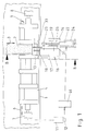
- Figure 1 shows a schematic representation of a plan view of the workpiece table of a crankshaft grinding machine with a measuring device according to the invention approximately in the direction of view indicated by arrow A in Figure 3.
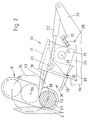
- Figure 2 shows a schematic view of the device according to the invention along the line B-B of Figure 1. The same parts are provided with the same reference numerals in the figures.
- FIG. 1 denotes the machine bed of a crankshaft grinding machine, on which a grinding headstock, not shown, with a grinding wheel 2 can be moved in the direction of the arrow 3.
- a workpiece table or workpiece slide 4 is guided in the direction of arrow 6 transversely to the grinding wheel 2 on the machine bed 1.
- the workpiece carriage 4 carries a workpiece headstock 7 and a tailstock 8 with centering tips, between which a crankshaft 9 is clamped in the usual way.
- the workpiece spindle is driven by a motor 11 which is connected to an angle sensor 12 for detecting the angular position of the crankshaft 9.
- the workpiece carriage 4 is positioned in the direction of the arrow 6 such that a crank pin 13 as a workpiece is in the machining position in front of the grinding wheel 2.
- a measuring device 16 for detecting the diameter of the crank pin 13 during its processing by the grinding wheel 2 is arranged on a console 14 of the machine bed 1.
- This measuring device 16 has a measuring head 17 with probes 18.
- the measuring head 17 is attached to a measuring head carrier 21 which can be pivoted about a pivot axis 19.
- the swivel drive 22 is articulated on a bracket 24 of the console 14.
- a bearing block 26 carries the pivot bearing 27 of the measuring head carrier 21.
- the bearing block 26 is positioned on the bracket in a receptacle 28 by means of a positioning element 29 in a correct position with respect to the rotating crank pin 13 and clamped by means of clamping means, for example clamping screws 31.
- the positioning element 29 has a stop surface 32 for the extreme lower pivoting position of the measuring head carrier 21 on.
- the measuring head carrier 21 is provided with a rigid guide ruler 33 which engages in the orbit 34 of the workpiece 13 around a circumferential axis 36, in the given example the crankshaft axis.
- the guide ruler 33 extends beyond the length of the key 18 tangentially to the circumferential surface 37 of the crank pin 13 into its path of movement.
- the measuring head 17 is pivoted by pivoting the measuring head carrier 21 by means of the drive 22 into its extreme lower position shown in FIG. 2, in which the measuring head carrier rests on the stop surface 32 of the positioning element 29. In this position, the measuring head 17 is aligned with the movement path 34 of the crank pin 13 in such a way that the peripheral surface 37 of the crank pin lies in a tangential sliding manner on a guide surface 38 of the guide ruler when it contacts the tip of the guide ruler 33. As the crank pin 13 moves further along its movement path 34, its peripheral surface 37 slides along the guide surface 38 and pivots the measuring head clockwise about the pivot axis 19. The drive 22 is switched off so that it does not oppose the pivoting movement of the measuring head 17 .
- crank pin 13 pivots the measuring head 17 further clockwise until the guide surface 38 of the guide ruler 33 in the exit position shown in FIG. 4 extends tangentially to the peripheral surface 37 of the crank pin 13.
- the crank pin 13 is released from the guide surface 38 of the guide ruler 33 in a sliding and shock-free manner. This may prevent the measurement from falsifying vibrations in the measuring head.
- the angle transmitter 12 (see FIG. 1) of the crankshaft drive 11 in a predetermined angular position of the crankshaft emits a signal to a control arrangement 44 which starts the swivel drive 22, which thereupon moved the measuring head carrier 21 with the measuring head 17 counterclockwise against the stop surface 32 in order to bring the measuring head into the position shown in FIG. 2, suitable for the next diameter measurement.
- the measuring head 17 is pivoted further clockwise by the swivel drive 22, starting from the position shown in FIG. 4, until its feelers move completely out of the range of motion of the rotating crank pin 13 are. This position is not shown.
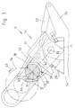
- Figures 5 to 9 show a variant of the diameter detection of an eccentrically rotating Workpiece with a measuring head, the pivoting movement of which is numerically controlled.
- the workpiece for example again a crank pin 13 of a crankshaft, which is otherwise not shown, rotates along the movement path 34 in the direction of arrow 43.
- this rotary movement is driven by the crankshaft drive 11, the angular position of which is detected by the rotary angle sensor 12.
- the angle encoder 12 generates angle signals corresponding to the angular position of the crankshaft, which it outputs to the control arrangement 44, for example the machine control.
- the measuring head is designed in the same way as that shown in connection with FIGS. 1 to 4 and is also designated by reference number 17.
- the structure of the measuring head arrangement is not shown again in FIGS. 5 to 9. It can be designed in the same way as shown in FIGS. 1 to 4, the swivel drive 22 and the stop surface 32 being eliminated.
- the pivoting movement of the measuring head 17 is driven by a motor 46, which is controlled by the control arrangement 44 as a function of the angular position of the workpiece 13 on its path of motion 34.
- the various positions which the measuring head 17 assumes during the detection of a workpiece diameter are shown in FIGS. 5 to 8.
- the measuring head 17 is pivoted into an entry position in which the buttons 18 are aligned tangentially to the circumferential surface 37 of the incoming crank pin 13 and engage in the movement path 34 of the crank pin.
- the crank pin 13 has moved into the detection area 39 between the buttons 18 of the measuring head 17, the contact between the buttons and the peripheral surface of the workpiece when entering the detection area is largely smooth and smooth due to the tangential orientation of the buttons.
- the crank pin 13 now continues to move along its path of motion 34, the measuring head 17 is simultaneously pivoted clockwise by its drive 46 depending on the angular position of the workpiece 13 about its axis 19, so that between the two buttons 18 and the workpiece always a stress-free touch takes place.
- the workpiece 13 has left the detection area 39 of the buttons 18 during its rotation along its movement path 34 and completes its rotation, while at the same time, which is not shown in FIGS. 5 to 9, is still in contact with the grinding wheel and ground becomes.
- the measuring head 17 is now pivoted counterclockwise around its pivot axis 19 into the entry position of FIG. 5 in order to be ready for the next diameter measurement in the next revolution of the workpiece.
- This return movement of the measuring head is controlled by the control arrangement 44 as a function of the angular position of the workpiece on its path of movement in order to avoid collisions between the workpiece and the probes during this return movement.
- FIG. 9 shows an inactive position of the measuring head 17, in which the diameter of the workpiece 13 is not detected when its axis passes through the connecting plane 42.
- the diameter D of an eccentrically rotating workpiece is therefore not recorded during the entire workpiece circulation, but only in a specific orbit section.
- This orbit section is defined by the overlap of the movement path 34 of the workpiece 13 with the detection area 39 between the probes 18 of the measuring head 17. It may be sufficient to detect the diameter of the workpiece 13 in this orbit section only once and through the control arrangement to one to process the corresponding diameter signal. It is of course also possible within the scope of the invention to record the diameter several times within the predetermined orbit section and to form corresponding single or average signals of the diameter. In any case, it is sufficient for the measurement-controlled grinding of eccentrically rotating workpieces to measure the diameter only once during the rotation. This applies in particular when the grinding wheel is not being fed in continuously, but rather the grinding wheel is infeed only once during each workpiece revolution.
- a commercially available measuring head with two measuring probes movable relative to one another is used for the diameter measurement.
- the absolute diameter measurement is also possible if a movable probe measures the workpiece diameter against a rigid reference element, ie the second probe is rigidly arranged on the measuring head as a reference element.
- This variant is not specifically shown in the drawing. It can be implemented by rigidly arranging or omitting the probe 18 lying on the side of the guide ruler 33 in the measuring head embodiment according to FIGS. 2 to 4.
- the guide ruler 33 then simultaneously fulfills the task of a rigid probe or reference element for the diameter detection with the second, movable probe.
Landscapes
- Engineering & Computer Science (AREA)
- Mechanical Engineering (AREA)
- Physics & Mathematics (AREA)
- General Physics & Mathematics (AREA)
- Machine Tool Sensing Apparatuses (AREA)
- Constituent Portions Of Griding Lathes, Driving, Sensing And Control (AREA)
- A Measuring Device Byusing Mechanical Method (AREA)
Applications Claiming Priority (2)
| Application Number | Priority Date | Filing Date | Title |
|---|---|---|---|
| DE19616353 | 1996-04-24 | ||
| DE19616353A DE19616353A1 (de) | 1996-04-24 | 1996-04-24 | Verfahren und Vorrichtung zum Messen des Durchmessers exzentrisch umlaufender Werkstücke |
Publications (2)
| Publication Number | Publication Date |
|---|---|
| EP0803323A1 true EP0803323A1 (fr) | 1997-10-29 |
| EP0803323B1 EP0803323B1 (fr) | 2000-11-15 |
Family
ID=7792300
Family Applications (1)
| Application Number | Title | Priority Date | Filing Date |
|---|---|---|---|
| EP97106038A Expired - Lifetime EP0803323B1 (fr) | 1996-04-24 | 1997-04-12 | Procédé et dispositif pour mesurer le diamètre d'un objet tournant excentriquement |
Country Status (2)
| Country | Link |
|---|---|
| EP (1) | EP0803323B1 (fr) |
| DE (2) | DE19616353A1 (fr) |
Cited By (7)
| Publication number | Priority date | Publication date | Assignee | Title |
|---|---|---|---|---|
| GB2329472A (en) * | 1997-09-23 | 1999-03-24 | Unova Uk Ltd | Workpiece gauging |
| EP0985493A3 (fr) * | 1998-09-08 | 2002-05-08 | Walter AG | Machine-outil avec commande/surveillance automatique d'opérations |
| CN103857493A (zh) * | 2011-09-27 | 2014-06-11 | 弗立兹·斯图特公司 | 机床及用于测量工件的方法 |
| CN107214575A (zh) * | 2017-07-31 | 2017-09-29 | 江西杰克机床有限公司 | 一种固定式砂轮防护罩上的翻转量仪测量装置 |
| CN107806809A (zh) * | 2017-10-30 | 2018-03-16 | 浙江精雷电器股份有限公司 | 一种偏心距采集检测设备 |
| CN113483643A (zh) * | 2021-07-05 | 2021-10-08 | 桂林福达曲轴有限公司 | 一种曲轴油孔偏心距的检验方法 |
| CN114111680A (zh) * | 2021-12-04 | 2022-03-01 | 陕西渭河工模具有限公司 | 一种螺尖丝锥斜槽芯径的高精度检测装置及检测方法 |
Families Citing this family (2)
| Publication number | Priority date | Publication date | Assignee | Title |
|---|---|---|---|---|
| DE102007060661B4 (de) * | 2007-12-17 | 2015-09-03 | Erwin Junker Maschinenfabrik Gmbh | Messvorrichtung, an einer Werkzeugmaschine, insbesondere Schleifmaschine, angeordnet, zur Bestimmung der Querschnittsabmessung von rotationssymmetrischen Werkstück-Bereichen |
| DE102012110673B4 (de) * | 2012-11-07 | 2014-05-15 | Fritz Studer Ag | Werkzeugmaschine und Verfahren zur Vermessung eines Werkstücks |
Citations (2)
| Publication number | Priority date | Publication date | Assignee | Title |
|---|---|---|---|---|
| DE3521710A1 (de) * | 1984-07-03 | 1986-01-09 | Schaudt Maschinenbau Gmbh, 7000 Stuttgart | Vorrichtung an einer werkzeugmaschine, insbesondere an einer schleifmaschine, zum messen des durchmessers exzentrisch umlaufender werkstuecke |
| DE4412682A1 (de) * | 1994-04-13 | 1995-10-26 | Doerries Scharmann Ag | Vorrichtung zum Vermessen exzentrisch umlaufender Werkstücke |
Family Cites Families (2)
| Publication number | Priority date | Publication date | Assignee | Title |
|---|---|---|---|---|
| DE2211590C3 (de) * | 1971-04-20 | 1980-04-17 | Veb Werkzeugmaschinenkombinat 7. Oktober Berlin, Ddr 1120 Berlin | Absolutmeßsteuergerät für Werkzeugmaschinen, insbesondere Schleifmaschinen |
| DE4419656C2 (de) * | 1994-06-06 | 1996-05-15 | Naxos Union Schleifmittel | Einrichtung zur Durchmesser- und/oder Rundheitsmessung beim exzentrischen Rundschleifen |
-
1996
- 1996-04-24 DE DE19616353A patent/DE19616353A1/de not_active Withdrawn
-
1997
- 1997-04-12 EP EP97106038A patent/EP0803323B1/fr not_active Expired - Lifetime
- 1997-04-12 DE DE59702626T patent/DE59702626D1/de not_active Expired - Fee Related
Patent Citations (2)
| Publication number | Priority date | Publication date | Assignee | Title |
|---|---|---|---|---|
| DE3521710A1 (de) * | 1984-07-03 | 1986-01-09 | Schaudt Maschinenbau Gmbh, 7000 Stuttgart | Vorrichtung an einer werkzeugmaschine, insbesondere an einer schleifmaschine, zum messen des durchmessers exzentrisch umlaufender werkstuecke |
| DE4412682A1 (de) * | 1994-04-13 | 1995-10-26 | Doerries Scharmann Ag | Vorrichtung zum Vermessen exzentrisch umlaufender Werkstücke |
Cited By (10)
| Publication number | Priority date | Publication date | Assignee | Title |
|---|---|---|---|---|
| GB2329472A (en) * | 1997-09-23 | 1999-03-24 | Unova Uk Ltd | Workpiece gauging |
| GB2329472B (en) * | 1997-09-23 | 2002-03-27 | Unova Uk Ltd | Improvements in and relating to workpiece gauging |
| EP0985493A3 (fr) * | 1998-09-08 | 2002-05-08 | Walter AG | Machine-outil avec commande/surveillance automatique d'opérations |
| CN103857493A (zh) * | 2011-09-27 | 2014-06-11 | 弗立兹·斯图特公司 | 机床及用于测量工件的方法 |
| CN103857493B (zh) * | 2011-09-27 | 2016-11-02 | 弗立兹·斯图特公司 | 机床及用于测量工件的方法 |
| CN107214575A (zh) * | 2017-07-31 | 2017-09-29 | 江西杰克机床有限公司 | 一种固定式砂轮防护罩上的翻转量仪测量装置 |
| CN107806809A (zh) * | 2017-10-30 | 2018-03-16 | 浙江精雷电器股份有限公司 | 一种偏心距采集检测设备 |
| CN113483643A (zh) * | 2021-07-05 | 2021-10-08 | 桂林福达曲轴有限公司 | 一种曲轴油孔偏心距的检验方法 |
| CN114111680A (zh) * | 2021-12-04 | 2022-03-01 | 陕西渭河工模具有限公司 | 一种螺尖丝锥斜槽芯径的高精度检测装置及检测方法 |
| CN114111680B (zh) * | 2021-12-04 | 2024-05-14 | 陕西渭河工模具有限公司 | 一种螺尖丝锥斜槽芯径的高精度检测装置及检测方法 |
Also Published As
| Publication number | Publication date |
|---|---|
| DE19616353A1 (de) | 1997-10-30 |
| DE59702626D1 (de) | 2000-12-21 |
| EP0803323B1 (fr) | 2000-11-15 |
Similar Documents
| Publication | Publication Date | Title |
|---|---|---|
| DE69605320T2 (de) | Vorrichtung zur prüfung des durchmessers von kurbelwellenzapfen rotierend mit einer orbitalen bewegung | |
| DE69901004T2 (de) | Verfahren und vorrichtung zur bearbeitung von vorbearbeiteten, verzahnten werkstücken wie zahnräder | |
| DE102008061444B4 (de) | Drehmaschine mit einer Messvorrichtung und Verfahren zum Vermessen eines Werkstückes auf solch einer Drehmaschine | |
| EP0252164B1 (fr) | Méthode et dispositif pour déterminer la position radiale d'un profil neuf obtenu par fraisage | |
| DE19928500B4 (de) | Verfahren und Vorrichtung zur automatischen Messung von Prozess- und Werkstückkennwerten beim Schleifen von Zahnrädern | |
| DE102007050111B4 (de) | Verfahren und Anlage-Sensorvorrichtung zu einer Anlagemessung bei einer Werkzeugmaschine | |
| DE19857364A1 (de) | Verfahren und Schleifmaschine zur Prozeßführung beim Schälschleifen eines Werkstückes | |
| DE2760477C2 (de) | Verfahren zum Schleifen einer Planfläche und einer daran anschließenden zylindrischen Längsfläche eines Werkstückes | |
| DE4420137A1 (de) | Meßgerät zur Überprüfung der Abmessungen von zylindrischen Werkstücken | |
| DE10030087B4 (de) | Verfahren und Vorrichtung zum Vermessen und Bearbeiten von Werkstücken | |
| DE102007050482B4 (de) | Verfahren und Vorrichtung zur Finishbearbeitung | |
| EP0803323B1 (fr) | Procédé et dispositif pour mesurer le diamètre d'un objet tournant excentriquement | |
| WO1998004379A1 (fr) | Machine a usiner des pieces avec des dents de coupe, notamment des lames de scie | |
| DE4419656C2 (de) | Einrichtung zur Durchmesser- und/oder Rundheitsmessung beim exzentrischen Rundschleifen | |
| DE69615259T2 (de) | Antrieb, Steuervorrichtung und sich darauf beziehendes Verfahren für eine Schleifmaschine | |
| DE4412682C2 (de) | Vorrichtung zum Vermessen exzentrisch umlaufender Werkstücke | |
| DE4432317B4 (de) | Meßvorrichtung für Spanwerkzeuge | |
| DE2537086C2 (de) | Einrichtung zum Messen des Verschleißes an einem abgefahrenen und nachzuarbeitenden Schienenrad an einer Drehmaschine | |
| EP0317760A1 (fr) | Tête de mesure rotative pour la palpation de surfaces cylindriques d'objets sous investigation | |
| DE3521710C2 (de) | Vorrichtung an einer Werkzeugmaschine, insbesondere an einer Schleifmaschine, zum Messen des Durchmessers exzentrisch umlaufender Werkstücke | |
| EP0315575A1 (fr) | Procédé et appareil de mesure pour la détermination du diamètre de roulement | |
| DE19609511A1 (de) | Hilfsvorrichtung für handgeführte Werkzeuge | |
| DE69712222T2 (de) | Verfahren zur steuerung einer werkzeugmaschine | |
| DE69705873T2 (de) | Schleifverfahren und -vorrichtung für zylindrische Werkstücke | |
| DE10205212A1 (de) | Meßeinrichtung für Maschinen zum Bearbeiten von Werkstücken, insbesondere von Kurbelwellen, Nockenwellen |
Legal Events
| Date | Code | Title | Description |
|---|---|---|---|
| PUAI | Public reference made under article 153(3) epc to a published international application that has entered the european phase |
Free format text: ORIGINAL CODE: 0009012 |
|
| AK | Designated contracting states |
Kind code of ref document: A1 Designated state(s): CH DE FR GB IT LI |
|
| 17P | Request for examination filed |
Effective date: 19980404 |
|
| 17Q | First examination report despatched |
Effective date: 19980930 |
|
| GRAG | Despatch of communication of intention to grant |
Free format text: ORIGINAL CODE: EPIDOS AGRA |
|
| 17Q | First examination report despatched |
Effective date: 19991018 |
|
| GRAG | Despatch of communication of intention to grant |
Free format text: ORIGINAL CODE: EPIDOS AGRA |
|
| GRAH | Despatch of communication of intention to grant a patent |
Free format text: ORIGINAL CODE: EPIDOS IGRA |
|
| GRAH | Despatch of communication of intention to grant a patent |
Free format text: ORIGINAL CODE: EPIDOS IGRA |
|
| GRAA | (expected) grant |
Free format text: ORIGINAL CODE: 0009210 |
|
| AK | Designated contracting states |
Kind code of ref document: B1 Designated state(s): CH DE FR GB IT LI |
|
| PG25 | Lapsed in a contracting state [announced via postgrant information from national office to epo] |
Ref country code: IT Free format text: LAPSE BECAUSE OF FAILURE TO SUBMIT A TRANSLATION OF THE DESCRIPTION OR TO PAY THE FEE WITHIN THE PRESCRIBED TIME-LIMIT;WARNING: LAPSES OF ITALIAN PATENTS WITH EFFECTIVE DATE BEFORE 2007 MAY HAVE OCCURRED AT ANY TIME BEFORE 2007. THE CORRECT EFFECTIVE DATE MAY BE DIFFERENT FROM THE ONE RECORDED. Effective date: 20001115 Ref country code: FR Free format text: LAPSE BECAUSE OF FAILURE TO SUBMIT A TRANSLATION OF THE DESCRIPTION OR TO PAY THE FEE WITHIN THE PRESCRIBED TIME-LIMIT Effective date: 20001115 |
|
| REG | Reference to a national code |
Ref country code: CH Ref legal event code: EP |
|
| GBT | Gb: translation of ep patent filed (gb section 77(6)(a)/1977) |
Effective date: 20001115 |
|
| REF | Corresponds to: |
Ref document number: 59702626 Country of ref document: DE Date of ref document: 20001221 |
|
| PG25 | Lapsed in a contracting state [announced via postgrant information from national office to epo] |
Ref country code: GB Free format text: LAPSE BECAUSE OF NON-PAYMENT OF DUE FEES Effective date: 20010412 |
|
| EN | Fr: translation not filed | ||
| PG25 | Lapsed in a contracting state [announced via postgrant information from national office to epo] |
Ref country code: LI Free format text: LAPSE BECAUSE OF NON-PAYMENT OF DUE FEES Effective date: 20010511 Ref country code: CH Free format text: LAPSE BECAUSE OF NON-PAYMENT OF DUE FEES Effective date: 20010511 |
|
| PLBE | No opposition filed within time limit |
Free format text: ORIGINAL CODE: 0009261 |
|
| STAA | Information on the status of an ep patent application or granted ep patent |
Free format text: STATUS: NO OPPOSITION FILED WITHIN TIME LIMIT |
|
| 26N | No opposition filed | ||
| GBPC | Gb: european patent ceased through non-payment of renewal fee |
Effective date: 20010412 |
|
| REG | Reference to a national code |
Ref country code: CH Ref legal event code: PL |
|
| PG25 | Lapsed in a contracting state [announced via postgrant information from national office to epo] |
Ref country code: DE Free format text: LAPSE BECAUSE OF NON-PAYMENT OF DUE FEES Effective date: 20020201 |