EP0803331B1 - Dispositif de serrage à genouillère pour la construction en carrosserie - Google Patents
Dispositif de serrage à genouillère pour la construction en carrosserie Download PDFInfo
- Publication number
- EP0803331B1 EP0803331B1 EP97104333A EP97104333A EP0803331B1 EP 0803331 B1 EP0803331 B1 EP 0803331B1 EP 97104333 A EP97104333 A EP 97104333A EP 97104333 A EP97104333 A EP 97104333A EP 0803331 B1 EP0803331 B1 EP 0803331B1
- Authority
- EP
- European Patent Office
- Prior art keywords
- piston rod
- toggle
- grip holder
- section
- switches
- Prior art date
- Legal status (The legal status is an assumption and is not a legal conclusion. Google has not performed a legal analysis and makes no representation as to the accuracy of the status listed.)
- Expired - Lifetime
Links
Images
Classifications
-
- B—PERFORMING OPERATIONS; TRANSPORTING
- B25—HAND TOOLS; PORTABLE POWER-DRIVEN TOOLS; MANIPULATORS
- B25B—TOOLS OR BENCH DEVICES NOT OTHERWISE PROVIDED FOR, FOR FASTENING, CONNECTING, DISENGAGING, OR HOLDING
- B25B5/00—Clamps
- B25B5/16—Details, e.g. jaws, jaw attachments
-
- B—PERFORMING OPERATIONS; TRANSPORTING
- B25—HAND TOOLS; PORTABLE POWER-DRIVEN TOOLS; MANIPULATORS
- B25B—TOOLS OR BENCH DEVICES NOT OTHERWISE PROVIDED FOR, FOR FASTENING, CONNECTING, DISENGAGING, OR HOLDING
- B25B5/00—Clamps
- B25B5/06—Arrangements for positively actuating jaws
- B25B5/12—Arrangements for positively actuating jaws using toggle links
- B25B5/122—Arrangements for positively actuating jaws using toggle links with fluid drive
-
- Y—GENERAL TAGGING OF NEW TECHNOLOGICAL DEVELOPMENTS; GENERAL TAGGING OF CROSS-SECTIONAL TECHNOLOGIES SPANNING OVER SEVERAL SECTIONS OF THE IPC; TECHNICAL SUBJECTS COVERED BY FORMER USPC CROSS-REFERENCE ART COLLECTIONS [XRACs] AND DIGESTS
- Y10—TECHNICAL SUBJECTS COVERED BY FORMER USPC
- Y10S—TECHNICAL SUBJECTS COVERED BY FORMER USPC CROSS-REFERENCE ART COLLECTIONS [XRACs] AND DIGESTS
- Y10S269/00—Work holders
- Y10S269/903—Work holder for electrical circuit assemblages or wiring systems
Definitions
- the invention relates to a toggle lever clamping device for the body shop with a rectangular in a cross-section perpendicular to the longitudinal axis of the piston rod cross-section, which is constructed from two housing parts, and with an axially extending to the cylinder-side end of the clamping head, in which an alternating on both sides by means of pressure medium pressure, in particular by air pressure to be acted upon pistons, which are guided in a longitudinally displaceable and sealing manner and which axially engages through the cylinder and a cavity of the clamping head with its piston rod, with a toggle joint arrangement which is coupled to a clamping arm being attached to the free end of the piston rod, with limit switches or Position transmitters in the form of microswitches, inductive switches, pneumatic switches or sensors which are integrated in a space of the clamping head, the switches being adjustable relative to one another and forming a cover for the same End holder are arranged and fastened as an overall interchangeable query cassette in the form of a board in the area of a slot in the
- Such a toggle lever tensioning device forms the subject of the applicant declining DE 93 11 132.0 U1 and the same European Patent application 0 636 449 (94 105 296.1-2302).
- no slot is provided, while in the embodiment 8 the cassette is grown from the side.
- DE-U-90 16 781.3 describes a tensioning device with an adjusting unit, Tension arm, end position interrogation devices and actuator stem with which the tension arm directly or indirectly between the end position sensing elements predetermined end positions is pivotable, previously known.
- the End position query elements are in a separate, with the clamping device Detachably connected housing in addition to an axial in this housing guided and adjustable sensor rod provided with position transmitter, which extends parallel to a housing connection surface and with its upper end protrudes from the housing, between the and the Position rod one with the upper end and the control rod axially fixed Driver crossbar is arranged.
- the end position query elements are in the housing is arranged adjustable in relation to the position transmitter.
- This Clamping device is arranged with a clamping arm in a on the drive unit fork-like head piece pivotally mounted.
- the case is on the Clamping arm side or the side of the device remote from the clamping arm with its housing connection surface arranged, the entrainer from the Guide rod between the fork parts of the head piece to the control rod extends.
- At least in one fork part of the head piece is laterally and parallel to the control rod a longitudinal slot and on the longitudinal slot side of the device arranged the housing, which is between the upper end of the Sensor rod and the actuator cross bar extending through extends the longitudinal slot.
- the control rod is with the tension arm from the drive unit simultaneously rotating and movable in the axial direction.
- the housing is arranged on one of the two sides of the device remote from the swivel range, the driver crossbar with the adjusting rod and / or the tension arm is rotatably connected.
- the connecting rod end of the driver crossbar on the rod side is fork-shaped.
- DE 30 22 376 C2 describes a toggle lever clamping device for clamping of workpieces, in particular body parts, consisting of a Pressure cylinder with double-acting piston and piston rod, previously known, the end of which is provided with a head piece which is in one on the cylinder guided axially attached guide piece and a hinged intermediate member movable with one on the guide piece on one side Swivel-mounted tension lever connected and via a flat guide is supported on the guide piece, this flat guide in one Plane is parallel to the one through the piston rod axis Level and on the side facing away from the swivel joint of the tensioning lever is arranged.
- the flat guide is on a maximum inner surface of the piston rod axis Guide piece arranged.
- a Stroke control element arranged near the flat guide.
- the invention has for its object a toggle lever device in the genre-presupposed kind in such a way that they do not only from the back, but also from all four sides of device parts can be added while maintaining the well-known cassette technology Advantages.
- the query cassette is removed from the Back of the tensioner housing through a narrow, slit-shaped recess inserted into the housing.
- the query cassette is only narrow designed and includes the sensors, the plugs that are wired together and any fastening nuts or screws.
- the cultivation option located there can be fully used means that the toggle clamp device can also be attached from this side.
- the toggle lever tensioning device can thus also be attached from the rear or consoles, brackets etc. located there can be screwed on become. Any limit switches, microswitches, adjustable inductive switches, sensors or the like, to set different opening angles, strokes or the like.
- the interrogation cassette has an approximately L-shaped shape in a section made orthogonal to the longitudinal axis of the piston rod, on the end of which a shape is orthogonal to the longitudinal axis of the L "running flange connects in one piece, with which the query cassette, covering the slot-shaped recess of the housing, is screwed to the housing.
- the rail of the query cassette extends in the longitudinal axis direction of the piston rod, that is to say runs parallel to the latter.
- the limit switches, microswitches, inductive switches or sensors are arranged in a variable position and are damped by a switching flag assigned to the piston rod, that is to say they are swept over when the piston rod is displaced and thereby trigger the various sequential controls.
- Claim 4 describes a further advantageous embodiment of the invention.
- a toggle lever clamping device in a device, for example for the body shop of the motor vehicle industry, requires a precise procedure to ensure that the clamping force is also guaranteed after the clamping arm has been set up.
- a screw is screwed in except for the block in the delivery state of the toggle lever tensioning device. Due to this screw position, the tab of the toggle lever tensioning device is at an angle of approximately 12 degrees. Now that the pressure piece has been attached to the clamping arm, this screw is unscrewed, up to the end stop.
- the toggle lever clamping device can then be moved to the dead center position by pressure medium pressure, for example by pneumatic pressure, as a result of which the full clamping force is applied.
- the toggle lever tensioning device can also be released from this over-dead center position by screwing in, if necessary, in order to enable manual opening or retraction of the toggle lever tensioning device.
- the screw thus serves to set up the tensioning device and to achieve the tensioning force and also to release the toggle lever tensioning device from the dead center or over dead center position ( claim 5 ).
- a threaded plug is provided, which is set as a further end stop of the toggle joint.
- the toggle lever joint moves against a stop, in the present case against a threaded plug, in order to thereby bring the tension arm into a play-free and absolutely fixed position.
- the threaded plug is adjustable from the outside and is therefore easy to assemble in order to compensate for any tolerances of the joint parts.
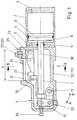
- the reference numeral 1 designates a clamping head on which axially one Cylinder 2 connects.
- the cylinder 2 is facing the clamping head 1 End through a cover 3 and on its opposite end face a bottom cover 4 delimited pressure-tight.
- a piston 6 is longitudinally displaceable in the cylinder 2 via a seal 5 guided longitudinally and sealingly, which is connected to a piston rod 7 is.
- the piston rod 7 passes through a bore 8 in the cover 3 and is sealed with a seal 9 fluid-tight.
- the piston rod 7 passes axially through the clamping head 1 and is at its end connected to a toggle joint assembly 10, which is an unspecified Clamp arm is assigned.
- the tension arm is in direction A or B pivotable about a certain opening angle about an axis 11 fixed to the housing arranged in the clamping head 1.
- the opening angle can be obtuse be.
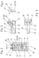
- the chuck 1 has a housing that in the illustrated embodiment consists of two shell-shaped housing parts 12 and 13 (FIG. 2), which lie on top of each other in a sandwich-like and gap-free manner and thus the piston rod 7, the toggle joint assembly 10 and all other between the Housing parts 12 and 13 objects are dirt and moisture proof encapsulate.
- the housing parts 12 and 13 are through a straight dividing plane 14 (Fig. 2) separated from each other, so that the housing parts 12 and 13 flat through walls 15 and 16, respectively, and by screws (not referred to) are releasably connected. If necessary, can the walls may also be assigned sealing elements (not shown).
- the housing parts 12 and 13 are closed on all sides and have only on one side each have an approximately semicircular recess (not shown), which thus complement each other through a bore through which the piston rod 7 in the space 17 delimited by the housing parts 12 and 13 protrudes.
- the toggle joint arrangement 10 is also arranged in this space 17. The end of the piston rod 7 located within the space 17 and the toggle joint arrangement 10 are thus dirt, dust and spray liquid tight encapsulated to the outside.
- the two shell-shaped housing parts 12 and 13 each have an orthogonally penetrating bore (not shown) through which the axis 11 passes. Instead, the Axis 11 but also in non-penetrating formations of the relevant housing part 12 or 13 may be mounted.
- the two shell-shaped housing parts 12 and 13 guide grooves (not shown) on.
- the guide grooves can be of the same design and with each other in the assembled state, the housing parts 12 and 13 correspond, such that the toggle joint assembly 10 with associated components in Longitudinal axis direction is performed.
- the housing parts 12 and 13 holes for screws, not shown, by means of which the housing parts 12 and 13 can be screwed together in a joint-tight manner.
- the holes of a housing part as through holes be formed while the associated coaxially arranged thereto Holes of the other housing part are blind holes with thread.
- By screwing in bolts can be the housing parts 12 and 13 releasably, but tightly connect.
- the Housing parts 12 and 13 can be made of steel or aluminum or another suitable workpiece, for example also from an injection molding material, consist.
- the walls 15, 16 can be of high quality at the parting plane 14 trained, for example ground or with appropriate surface quality be poured so that they are full and tight on one another.
- the toggle joint arrangement 10 can be assigned fork arms (not shown) be with their ends square or polygonal in cross section designed end portions of the axis 11 are arranged. For this may be provided a tab that against the fork-shaped end of the assigned fork arm attacks and with formally adapted recesses engages around the end sections of the pivot pin and with the relevant one Fork arm is connected by screws (also not shown).
- the housing of the clamping head 1 is in an orthogonal to the longitudinal axis 18 of the piston rod 7 cross section rectangular educated.
- this means that the housing can be namely on the opposite sides of the rectangle either on device parts, for example in the body shop of the automotive industry, grown, for example screwed on.
- Fig. 2 shows that in the area of one narrow side of the rectangular Basic shape of the housing, a slot 19 of width X is arranged is (Fig. 1) extends approximately over the length Y and in which a query cassette 20 is arranged.
- This query cassette 20 essentially consists from a guided in an orthogonal to the longitudinal axis 18 of the piston rod 7
- Cross-section L-shaped profile 21 which is designed as a mounting rail and has two spaced switches 22 and 23, respectively
- Microswitches, inductive switches, limit switches or pneumatic switches can be and adjustable in the longitudinal axis direction of the L-profile 21 and are arranged lockable, depending on the desired operating conditions.
- switches 22 and 23 are parallel to the Parting plane 14 extending web of the L-profile 21 attached during this orthogonal transverse web 24 is arranged in the slot 19 and seals it as joint-tight as possible to the outside and thus space 17 also closes to the outside here.
- the crossbar 24 extends over the Length Y (FIG. 1) of the slot 19.
- a flange 25 is suitably made in one piece with the L-shaped profile 21 connected, the present two through holes 26 (Fig. 5) for arrangement of the feeders 27 and 28 for electrical cables 29 and 30, respectively are connected to switches 22 and 23.
- the flange 25 a through hole 31 through which a screw, not shown reaches through, by means of which the query cassette 20 on the clamping head 1 can be exchanged is attached.
- a switching flag 32 is connected to the piston rod 7, which is arranged with a gap distance to the switches 22 and 23 and at damped the reciprocation of the piston rod 7 and thereby switching functions triggers.
- the query cassette 20 with the L-shaped profile 21 within the contours of the housing comes to lie so that it does not interfere with the outside. Only the feeders 27 and 28 protrude above the projection.
- the flange 25 is also on the outside arranged the housing 1. However, this also gives the opportunity to side of the toggle clamp device, i.e. from the back to install any device parts.
- the reference numeral 34 denotes an adjusting screw, which is also is accessible from the outside. Assembling a toggle clamp of the shown construction namely requires a precise procedure to ensure that the clamping force after setting up the clamping arm too is actually guaranteed. To achieve this, the adjusting screw 34 when leaving the manufacturing plant down to the block, i.e. fully screwed in. Due to this screw position, the tab of the toggle joint arrangement is located 10 at an angle of about 12 degrees. Now that Pressure piece was attached to the clamping arm, which later on the workpiece acts, the adjusting screw 34 is unscrewed to a further end stop. The toggle clamp device can now by the appropriate Pressurizing the piston 6 to the dead center position be driven, i.e. apply their maximum resilience.
- the toggle lever clamping device from its dead center position can be easily solved to manually open or retract the To enable Spanners.
- the adjustment screw 34 is also used for setting up of the clamping arm and for achieving the clamping force.
Landscapes
- Engineering & Computer Science (AREA)
- Mechanical Engineering (AREA)
- Jigs For Machine Tools (AREA)
- Clamps And Clips (AREA)
- A Measuring Device Byusing Mechanical Method (AREA)
- Mechanical Control Devices (AREA)
Claims (6)
- Dispositif de serrage à genouillère pour la construction de carrosseries, comprenant une tête de serrage (1) rectangulaire guidée dans une section perpendiculaire à l'axe longitudinal (18) de la tige (7) du piston, laquelle tête de serrage est formée de deux pièces de boítier (12, 13), et comprenant un vérin (2) raccordé à l'extrémité de la tête de serrage (1) côté vérin pour en former le prolongement axial, vérin dans lequel est guidé longitudinalement et alternativement dans les deux sens sous l'effet de la pression d'un fluide sous pression, en particulier de l'air comprimé, un piston (6) étanchant dont la tige (7) traverse axialement le vérin (2) et une cavité de la tête de serrage (1), un ensemble articulé à genouillère (10) étant fixé contre l'extrémité libre de la tige de piston (7), cet ensemble étant couplé à un bras de serrage, à des commutateurs fin de course et transmetteurs de position en forme de microcommutateurs, détecteurs inductifs, commutateurs pneumatiques ou sondes (22, 23) intégrés dans un compartiment (17) de la tête de serrage (1), ces commutateurs (22, 23) étant réglables les uns relativement aux autres et étant agencés et fixés contre une fixation officiant de couvercle pour ces commutateurs, donnant ainsi une cassette de captage (20) interchangeable en bloc et se présentant en forme de platine située et fixée dans la zone d'une fente (19) dans le sens axial de la tête de serrage (1), cette cassette de captage (20) présentant vue de dessus une géométrie en "T" avec un rail de fixation et une bride (25) à laquelle vient se raccorder un profilé (21) dont l'axe longitudinal est parallèle à l'axe longitudinal (18) de la tige du piston, caractérisé en ce que la cassette de captage (20) s'enfiche par le dos du boítier de la tête de serrage (1), via une fente étroite (19) s'étendant en direction de l'axe longitudinal (18) de la tige du piston (7) tout en conservant le possibilité de monter le dispositif de serrage à genouillère rapporté par ses quatre côtés et en particulier par son dos, de telle sorte que le profilé (21) rende la fente (19) la plus hermétique possible par rapport à l'extérieur au moyen de joints étanches.
- Dispositif de serrage à genouillère selon la revendication 1, caractérisé en ce que le profilé (21) présente, perpendiculaire à l'axe longitudinal (18) de la tige de piston (7), une section en forme de "L", la branche longue du "L" ayant un tracé parallèle à l'axe longitudinal (18) de la tige de piston (7), et présentant des commutateurs (22, 23) déplaçables, tandis que la branche transversale (24) du "L" obture la fente (19) par rapport à l'extérieur.
- Dispositif de serrage à genouillère selon la revendication 1 ou 2, comportant une tête de serrage (1) formée de deux pièces de boítier (12, 13) en forme de coquilles dont les surfaces appliquent l'une sur l'autre sur un plan et encapsulent de manière étanche aux salissures et à la poussière extérieures l'ensemble articulé à genouillère (10), la tige de piston (7), les commutateurs fin de course (22, 23), caractérisé en ce que les deux pièces de boítier (12, 13) en forme de coquilles présentent, sur le côté plus étroit de la tête de serrage (1) de section rectangulaire, la fente (19) servant à agencer la cassette de captage (20).
- Dispositif de serrage à genouillère selon la revendication 2 ou 3, caractérisé en ce que le profilé (21) plonge dans la fente (19) à une profondeur telle qu'un côté, le côté plus étroit de la tête de serrage (1) à section rectangulaire, fait salle au-dessus de la limitation, regardant vers l'extérieur, du profilé en "L" (21).
- Dispositif de serrage à genouillère selon la revendication 4, avec une butée finale (33) pour l'ensemble articulé à genouillère (10), butée positionnée de préférence au point mort haut de l'articulation à genouillère, caractérisé en ce que la butée fin de course (33) est configurée en butée actionnable de l'extérieur et déplaçable dans le sens de son axe longitudinal, en particulier configurée en bouchon fileté (33).
- Dispositif de serrage à genouillère selon la revendication 5, caractérisé en ce que côté frontal est agencé, contre la tête de serrage (1), une autre butée finale (34) déplaçable permettant de faire quitter manuellement son point mort haut à l'ensemble articulé à genouillère.
Applications Claiming Priority (2)
| Application Number | Priority Date | Filing Date | Title |
|---|---|---|---|
| DE19616441 | 1996-04-25 | ||
| DE19616441A DE19616441C1 (de) | 1996-04-25 | 1996-04-25 | Kniehebelspannvorrichtung für den Karosseriebau |
Publications (2)
| Publication Number | Publication Date |
|---|---|
| EP0803331A1 EP0803331A1 (fr) | 1997-10-29 |
| EP0803331B1 true EP0803331B1 (fr) | 1999-08-04 |
Family
ID=7792358
Family Applications (1)
| Application Number | Title | Priority Date | Filing Date |
|---|---|---|---|
| EP97104333A Expired - Lifetime EP0803331B1 (fr) | 1996-04-25 | 1997-03-14 | Dispositif de serrage à genouillère pour la construction en carrosserie |
Country Status (4)
| Country | Link |
|---|---|
| US (1) | US5845897A (fr) |
| EP (1) | EP0803331B1 (fr) |
| DE (1) | DE19616441C1 (fr) |
| ES (1) | ES2135962T3 (fr) |
Cited By (1)
| Publication number | Priority date | Publication date | Assignee | Title |
|---|---|---|---|---|
| DE202014102804U1 (de) | 2014-05-22 | 2014-07-29 | Pepperl + Fuchs Gmbh | Geber für Kraftspanner |
Families Citing this family (66)
| Publication number | Priority date | Publication date | Assignee | Title |
|---|---|---|---|---|
| DE19702204C1 (de) * | 1997-01-23 | 1998-04-23 | Sta Co Mettallerzeugnisse Gmbh | Pneumatische Endstellungsabfrageeinrichtung |
| DE19702203A1 (de) * | 1997-01-23 | 1998-07-30 | Sta Co Mettallerzeugnisse Gmbh | Pneumatische Endstellungsabfrageeinrichtung |
| FR2769255B1 (fr) * | 1997-10-08 | 1999-12-03 | Genus Technologie Ind | Dispositif de maintien, de positionnement, ou de serrage |
| DE19751950C1 (de) * | 1997-11-24 | 1999-03-04 | Isi International Sa | Kniehebelspannvorrichtung, insbesondere zur Verwendung im Karosseriebau der Kfz-Industrie |
| DE19801433A1 (de) * | 1998-01-16 | 1999-07-22 | Sta Co Mettallerzeugnisse Gmbh | Spannvorrichtung |
| DE19808631A1 (de) * | 1998-02-28 | 1999-09-02 | Sta Co Mettallerzeugnisse Gmbh | Spannvorrichtung |
| US6192284B1 (en) | 1998-05-15 | 2001-02-20 | Norgren Automotive, Inc. | Clamping arm position sensing apparatus |
| DE19824579C1 (de) * | 1998-06-02 | 1999-06-17 | Tuenkers Maschinenbau Gmbh | Kniehebelspannvorrichtung, insbesondere zur Verwendung im Karosseriebau der Kfz-Industrie |
| US6189877B1 (en) | 1998-06-26 | 2001-02-20 | Genus Technologies | Device for positioning, holding or gripping |
| FR2780324B1 (fr) * | 1998-06-26 | 2000-08-18 | Genus Technologies | Dispositif de positionnement, de maintien ou de serrage |
| DE29903281U1 (de) | 1999-02-24 | 1999-07-01 | Festo AG & Co, 73734 Esslingen | Kniehebel-Spannvorrichtung |
| CN1104999C (zh) * | 1999-04-28 | 2003-04-09 | Smc株式会社 | 夹紧装置 |
| JP3634190B2 (ja) * | 1999-05-24 | 2005-03-30 | Smc株式会社 | クランプ装置 |
| DE19930990C1 (de) * | 1999-07-05 | 2000-12-28 | Tuenkers Maschinenbau Gmbh | Kraftangetriebene Kniehebelspannvorrichtung, insbesondere zur Verwendung im Karosseriebau der Kfz-Industrie |
| DE19931723C1 (de) * | 1999-07-08 | 2000-09-21 | Tuenkers Maschinenbau Gmbh | Kraftangetriebene Kniehebelspannvorrichtung zur Verwendung im Karosseriebau der Kfz-Industrie |
| DE19931987C1 (de) * | 1999-07-09 | 2000-10-19 | Tuenkers Maschinenbau Gmbh | Verfahren zum Feststellen von Funktionsstörungen an Spannvorrichtungen, insbesondere an Kniehebelspannvorrichtungen, zur Verwendung im Karosseriebau der Kfz-Industrie, und Vorrichtung zum Durchführen dieses Verfahrens |
| US6557452B1 (en) | 1999-07-16 | 2003-05-06 | Norgren Automotive, Inc. | Valve and position control system integrable with clamp |
| JP3683447B2 (ja) * | 1999-10-15 | 2005-08-17 | Smc株式会社 | クランプ装置 |
| DE10047798A1 (de) * | 2000-09-23 | 2002-04-18 | Ms Trade Gmbh & Co | Abstützvorrichtung für eine Golftasche |
| US6502880B1 (en) | 2000-03-08 | 2003-01-07 | Btm Corporation | Pin part locator |
| DE10013874B4 (de) * | 2000-03-21 | 2013-04-18 | De-Sta-Co Metallerzeugnisse Gmbh | Kniehebelspannvorrichtung mit Öffnungswinkelbegrenzung |
| US6565074B1 (en) * | 2001-06-26 | 2003-05-20 | Norgren Automotive, Inc. | Rotary clamp having an adjustable pre-stop |
| US6666489B2 (en) | 2001-08-23 | 2003-12-23 | Btm Corporation | Sealed gripper apparatus |
| DE10159874C1 (de) | 2001-12-06 | 2003-02-27 | Tuenkers Maschinenbau Gmbh | Werkzeug |
| EP1355424A1 (fr) * | 2002-04-17 | 2003-10-22 | Senstronic, S.A. | Dispositif capteur comprenant des unités sans fil de détection pour un dispositif de serrage |
| US6786478B2 (en) * | 2002-07-10 | 2004-09-07 | Welker Bearing Company | Locating assembly having an extendable clamping finger |
| US6988440B2 (en) * | 2002-07-18 | 2006-01-24 | Phd, Inc. | Rotary actuator assembly |
| ITMI20021914A1 (it) | 2002-09-10 | 2004-03-11 | Univer Spa | Dispositivo di bloccaggio con leva manuale di comando |
| US7114408B2 (en) * | 2003-01-30 | 2006-10-03 | Delaware Capital Formation, Inc. | Drop away leaf pivot unit |
| FR2852873B1 (fr) * | 2003-03-24 | 2005-05-27 | Usines Quiri Et Cie Soc D | Dispositif a commande de deplacement hydraulique muni de moyens de detection pneumatique sans fuite des positions |
| ITMI20030667A1 (it) * | 2003-04-04 | 2004-10-05 | Univer Spa | Apparecchiatura di bloccaggio con dispositivo lineare indicizzato di rilevamento delle posizioni dell'organo di bloccaggio |
| BR0301329B1 (pt) * | 2003-05-12 | 2011-09-06 | suporte de sensor de proximidade, compressor, placa de válvulas e refrigerador. | |
| US7815176B2 (en) | 2003-09-11 | 2010-10-19 | Phd, Inc. | Lock mechanism for pin clamp assembly |
| KR100520991B1 (ko) * | 2003-09-15 | 2005-10-11 | 현대모비스 주식회사 | 오디오/비디오 시스템의 구동부 어셈블리 |
| ITTO20030814A1 (it) | 2003-10-16 | 2005-04-17 | Vep Automation Srl | Gruppo di controllo delle posizioni di fine corsa angolare del braccio di serraggio di un dispositivo di chiusura a leva articolata. |
| DE102004007346B3 (de) * | 2003-11-04 | 2005-04-21 | Tünkers Maschinenbau Gmbh | Kniehebelspannvorrichtung - auch Spannwerkzeug wie Punktschweißvorrichtung mit Kniehebelgelenkanordnung, oder Clinchwerkzeug mit Kniehebelgelenkanordnung oder dergleichen -, zur Verwendung im Karosseriebau der Kfz-Industrie |
| US20070023410A1 (en) * | 2003-11-24 | 2007-02-01 | Miguel Sarabia Trilla | Clamping jaw for automated welding installations |
| DE102004007463A1 (de) * | 2004-02-13 | 2005-09-01 | De-Sta-Co Metallerzeugnisse Gmbh | Antriebsvorrichtung |
| DE102004007465A1 (de) * | 2004-02-13 | 2005-09-01 | De-Sta-Co Metallerzeugnisse Gmbh | Antriebsvorrichtung |
| US7182326B2 (en) | 2004-04-02 | 2007-02-27 | Phd, Inc. | Pin clamp |
| US7516948B2 (en) | 2004-04-02 | 2009-04-14 | Phd, Inc. | Pin clamp accessories |
| DE102004018195B4 (de) * | 2004-04-15 | 2006-12-14 | Tünkers Maschinenbau Gmbh | Kniehebelspannvorrichtung zum Spannen, Clinchen, Kleben, Schweißen oder dergleichen, vornehmlich zur Verwendung im Karosseriebau der Kfz-Industrie |
| ITMI20041584A1 (it) * | 2004-08-02 | 2004-11-02 | Univer Spa | Sistema per la rilevazione di posizioni operative per un dispositivo di ritegno per pezzi da lavorare |
| US7448607B2 (en) | 2004-12-15 | 2008-11-11 | Phd, Inc. | Pin clamp assembly |
| DE102005004908B4 (de) * | 2005-02-02 | 2011-03-17 | Ifm Electronic Gmbh | Anschlagselement zur axialen Begrenzung der Position eines Sensors |
| DE102006041707B4 (de) * | 2006-05-10 | 2009-01-02 | Tünkers Maschinenbau Gmbh | Kolben-Zylinder-Einheit (Arbeitszylinder) zum Spannen, und/oder Pressen, und/oder Fügen, und/oder Stanzen, und/oder Prägen, und/oder Lochen und/oder Schweißen, zum Beispiel unter Zwischenschaltung einer Kniehebelgelenkanordnung |
| DE102006022950A1 (de) * | 2006-05-17 | 2007-11-22 | De-Sta-Co Europe Gmbh | Spannvorrichtung zum Festlegen von Werkstücken |
| ES2707249T3 (es) | 2007-06-19 | 2019-04-03 | Phd Inc | Conjunto de abrazadera de pasador |
| DE202008012622U1 (de) | 2007-08-13 | 2008-12-24 | De-Sta-Co Europe Gmbh | Spannvorrichtung |
| WO2009155261A1 (fr) | 2008-06-18 | 2009-12-23 | Phd, Inc. | Pince à broche à enlèvement |
| DE202008009702U1 (de) | 2008-07-17 | 2008-09-25 | Tünkers Maschinenbau Gmbh | Kniehebelspannvorrichtung, insbesondere zur Verwendung im Karosseriebau der Kfz-Industrie |
| DE202009002141U1 (de) | 2009-02-14 | 2009-04-23 | Tünkers Maschinenbau Gmbh | Vorrichtung mit einem über ein Stellglied und einer Kniehebelgelenkanordnung durch einen Antrieb in entgegengesetzten Richtungen antreibbaren Hebel, dem eine oder mehrere Massen zugeordnet ist bzw. sind, insbesondere zur Verwendung im Karosseriebau der Kfz-Industrie |
| DE102009048510A1 (de) | 2009-10-09 | 2011-04-14 | De-Sta-Co Europe Gmbh | Spannvorrichtung |
| DE102009054153A1 (de) | 2009-11-23 | 2011-05-26 | De-Sta-Co Europe Gmbh | Spannvorrichtung |
| WO2012045320A1 (fr) | 2010-10-06 | 2012-04-12 | Tünkers Maschinenbau Gmbh | Unité piston-cylindre (cylindre de travail) économe en énergie, en particulier pour une utilisation dans la construction de carrosserie de l'industrie automobile |
| US9453521B1 (en) | 2011-12-30 | 2016-09-27 | Lincoln Global IP | Clamp and method of use |
| DE202012013044U1 (de) * | 2012-02-28 | 2014-11-12 | Springer Gmbh | Antriebsvorrichtung zum Antreiben einer Vorrichtung zum Greifen und/oder Spannen eines Werkstückes, wie zum Beispiel eines Bleches oder dergleichen, und Vorrichtungen zum Greifen und/oder Spannen eines Werkstückes |
| US10625382B2 (en) | 2012-08-01 | 2020-04-21 | Delaware Capital Formation, Inc. | Toggle lever clamp |
| DE102013107661A1 (de) | 2013-07-18 | 2015-01-22 | Behringer Gmbh | Werkstück-Spannvorrichtung, Werkzeugmaschine und Verfahren zum Einspannen eines Werkstücks |
| DE202014103575U1 (de) * | 2014-08-01 | 2014-09-02 | Pepperl + Fuchs Gmbh | Abfrageeinheit für Kniehebelspanner |
| EP3116685B1 (fr) | 2015-04-29 | 2017-08-30 | Pneumax S.p.A. | Dispositif a actuation du type pourvu d'un élément d'actuation et des moyens de détection pour révéler le positionnement de l'élément d'actuation |
| CN108620916B (zh) * | 2018-06-14 | 2023-12-29 | 苏州利航精密制造有限公司 | 一种航空零件车加工夹具 |
| US10967472B2 (en) * | 2018-09-18 | 2021-04-06 | Hammill Manufacturing Company, Co-op Tool Divison | Position detection device |
| CN112848829A (zh) * | 2021-03-15 | 2021-05-28 | 中国第一汽车股份有限公司 | 前滑柱总成与转向节总成装配角度控制调整装置及方法 |
| CN113953608B (zh) * | 2021-10-26 | 2022-08-12 | 首都航天机械有限公司 | 一种电火花加工锁柄v型槽专用夹具 |
| DE102022122108B3 (de) * | 2022-09-01 | 2024-01-18 | Destaco Europe Gmbh | Positioniervorrichtung mit Stellglied und Gegenanschlag aus Keilelementen |
Family Cites Families (15)
| Publication number | Priority date | Publication date | Assignee | Title |
|---|---|---|---|---|
| US3371953A (en) * | 1967-03-16 | 1968-03-05 | Leland F. Blatt | Gripper |
| US3482831A (en) * | 1967-09-11 | 1969-12-09 | Leland F Blatt | Toggle action jaw type gripper |
| DE3022376C2 (de) * | 1980-06-14 | 1985-08-01 | De-Sta-Co Metallerzeugnisse Gmbh, 6000 Frankfurt | Kniehebelspannvorrichtung zum Festspannen von Werkstücken |
| US4635911A (en) * | 1985-08-30 | 1987-01-13 | Lovrenich Rodger T | Motorized over center clamp |
| US4664364A (en) * | 1986-08-15 | 1987-05-12 | Ozz Industries, Inc. | Proximity switch assembly |
| ES2023238B3 (es) * | 1987-10-29 | 1992-01-01 | De-Sta-Co Metallerzeugnisse Gmbh | Montaje de fijacion |
| US4905973B1 (en) * | 1989-01-11 | 1994-07-05 | John A Blatt | Power operated clamp with externally mounted adjustable clamp arm |
| US5201838A (en) * | 1989-09-05 | 1993-04-13 | Philippe Roudaut | Position indicator for a piston controlled robot part |
| FR2651543B1 (fr) * | 1989-09-05 | 1991-12-06 | Roudaut Philippe | Ensemble piston-cylindre muni de moyens de determination et de validation de la position du piston. |
| US5072652A (en) * | 1990-11-16 | 1991-12-17 | Blatt John A | Gripping device having impact cushioning means |
| DE9215151U1 (de) * | 1992-05-14 | 1993-01-21 | De-Sta-Co Metallerzeugnisse Gmbh, 6000 Frankfurt | Spannvorrichtung |
| DE4236670A1 (de) * | 1992-10-30 | 1994-05-05 | Sta Co Mettallerzeugnisse Gmbh | Klemmspannvorrichtung |
| DE9311132U1 (de) * | 1993-07-26 | 1993-09-09 | Tünkers Maschinenbau GmbH, 40880 Ratingen | Kniehebelspannvorrichtung für den Karosseriebau |
| DE9412722U1 (de) * | 1994-08-06 | 1994-09-29 | DE-STA-CO Metallerzeugnisse GmbH, 61449 Steinbach | Kniehebelspannvorrichtung |
| DE29513586U1 (de) * | 1995-08-24 | 1995-12-07 | Tünkers Maschinenbau GmbH, 40880 Ratingen | Kniehebelspannvorrichtung für den Karosseriebau |
-
1996
- 1996-04-25 DE DE19616441A patent/DE19616441C1/de not_active Expired - Lifetime
-
1997
- 1997-03-14 EP EP97104333A patent/EP0803331B1/fr not_active Expired - Lifetime
- 1997-03-14 ES ES97104333T patent/ES2135962T3/es not_active Expired - Lifetime
- 1997-04-17 US US08/842,829 patent/US5845897A/en not_active Expired - Lifetime
Cited By (5)
| Publication number | Priority date | Publication date | Assignee | Title |
|---|---|---|---|---|
| DE202014102804U1 (de) | 2014-05-22 | 2014-07-29 | Pepperl + Fuchs Gmbh | Geber für Kraftspanner |
| DE102014107267A1 (de) | 2014-05-22 | 2015-11-26 | Pepperl + Fuchs Gmbh | Geber für Kraftspanner |
| WO2015177291A1 (fr) | 2014-05-22 | 2015-11-26 | Pepperl + Fuchs Gmbh | Capteur pour dispositif de serrage électrique |
| DE102014107267B4 (de) | 2014-05-22 | 2019-06-13 | Pepperl + Fuchs Gmbh | Kniehebelspannvorrichtung mit Abfrageeinheit sowie Abfrageeinheit für eine vereinfachte Montage |
| US10688626B2 (en) | 2014-05-22 | 2020-06-23 | Pepperl+Fuchs Gmbh | Sensor for power clamp |
Also Published As
| Publication number | Publication date |
|---|---|
| US5845897A (en) | 1998-12-08 |
| DE19616441C1 (de) | 1997-06-26 |
| EP0803331A1 (fr) | 1997-10-29 |
| ES2135962T3 (es) | 1999-11-01 |
Similar Documents
| Publication | Publication Date | Title |
|---|---|---|
| DE19616441C1 (de) | Kniehebelspannvorrichtung für den Karosseriebau | |
| EP0962285B1 (fr) | Dispositif de serrage à genouillère, en particulier pour la construction en carrosserie dans l'industrie automobile | |
| DE10159874C1 (de) | Werkzeug | |
| EP1309426B1 (fr) | Dispositif de serrage a genouillere | |
| EP0769353A1 (fr) | Dispositif de serrage à grenouillère | |
| DE102013001004B3 (de) | Vorrichtung zum Spannen, Prägen, Schweißen, Clinchen oder Schwenken von Bauteilen, mit einer Sensorvorrichtung zur Positionsbestimmung eines länglichen Verstellteils, welches mit einem Kniehebelgelenk ein schwenkbares Vorrichtungsteil antreibt | |
| EP2329153A1 (fr) | Dispositif à entraînement par air comprimé, équipé d'une fonction double piston et destiné à être utilisé dans le domaine de la carrosserie pour l'industrie automobile | |
| EP0636449B1 (fr) | Dispositif de serrage avec levier à genouillère pour la construction en carrosserie | |
| DE102004040606B3 (de) | Als Gripper ausgebildete Kniehebelspannvorrichtung, insbesondere zur Verwendung im Karosseriebau der Kfz-Industrie | |
| DE202009008068U1 (de) | Vorrichtung zum Spannen und/oder Fügen und/oder Stanzen und/oder Prägen und/oder Schweißen und/oder Lochen und/oder Clinchen und/oder Schwenken, insbesondere zur Verwendung im Karosseriebau der Kfz-Industrie sowie Steuerung für eine derartige Vorrichtung und die Verwendung einer solchen Vorrichtung, vornehmlich für den Karosseriebau der Kfz-Industrie | |
| DE20004406U1 (de) | Kniehebelspannvorrichtung, insbesondere zur Verwendung im Karosseriebau der Kfz-Industrie | |
| DE29615157U1 (de) | Kniehebelspann- und Greifvorrichtung | |
| AT407628B (de) | Halterung für einen am fahrerhausdach eines lastkraftwagens angeordneten dachspoiler | |
| DE29701730U1 (de) | Kniehebelspannvorrichtung, insbesondere zur Verwendung in Vorrichtungen und Schweißmaschinen des Karosseriebaus der Kfz-Industrie | |
| DE29504267U1 (de) | Kniehebelspannvorrichtung, insbesondere zur Verwendung im Karosseriebau der Kfz-Industrie | |
| EP3145676B1 (fr) | Capteur pour dispositif de serrage électrique | |
| EP0209869B1 (fr) | Dispositif pour pivoter l'arbre d'un assemblage antidérapant à centrifuge de véhicules automobiles | |
| DE29718644U1 (de) | Abfragekassette | |
| DE19525611C2 (de) | Spritzpistole, insbesondere Lackierpistole | |
| DE29513586U1 (de) | Kniehebelspannvorrichtung für den Karosseriebau | |
| DE3831378C2 (de) | Anschlagvorrichtung für Tischsägen | |
| DE19930990C1 (de) | Kraftangetriebene Kniehebelspannvorrichtung, insbesondere zur Verwendung im Karosseriebau der Kfz-Industrie | |
| DE20301189U1 (de) | Verbesserter Formsitz zur Verankerung des Formwerkzeuges einer Spritzmaschine | |
| DE20203790U1 (de) | Kniehebelspannvorrichtung | |
| DE29822135U1 (de) | Als Handspanner ausgebildete Kniehebelspannvorrichtung, insbesondere zur Verwendung im Karosseriebau der Kfz-Industrie |
Legal Events
| Date | Code | Title | Description |
|---|---|---|---|
| PUAI | Public reference made under article 153(3) epc to a published international application that has entered the european phase |
Free format text: ORIGINAL CODE: 0009012 |
|
| 17P | Request for examination filed |
Effective date: 19970326 |
|
| AK | Designated contracting states |
Kind code of ref document: A1 Designated state(s): ES FR GB |
|
| GRAG | Despatch of communication of intention to grant |
Free format text: ORIGINAL CODE: EPIDOS AGRA |
|
| GRAG | Despatch of communication of intention to grant |
Free format text: ORIGINAL CODE: EPIDOS AGRA |
|
| GRAH | Despatch of communication of intention to grant a patent |
Free format text: ORIGINAL CODE: EPIDOS IGRA |
|
| GRAG | Despatch of communication of intention to grant |
Free format text: ORIGINAL CODE: EPIDOS AGRA |
|
| 17Q | First examination report despatched |
Effective date: 19980911 |
|
| GRAH | Despatch of communication of intention to grant a patent |
Free format text: ORIGINAL CODE: EPIDOS IGRA |
|
| GRAG | Despatch of communication of intention to grant |
Free format text: ORIGINAL CODE: EPIDOS AGRA |
|
| GRAA | (expected) grant |
Free format text: ORIGINAL CODE: 0009210 |
|
| AK | Designated contracting states |
Kind code of ref document: B1 Designated state(s): ES FR GB |
|
| REG | Reference to a national code |
Ref country code: ES Ref legal event code: FG2A Ref document number: 2135962 Country of ref document: ES Kind code of ref document: T3 |
|
| ET | Fr: translation filed | ||
| GBT | Gb: translation of ep patent filed (gb section 77(6)(a)/1977) |
Effective date: 19991108 |
|
| PLBQ | Unpublished change to opponent data |
Free format text: ORIGINAL CODE: EPIDOS OPPO |
|
| PLBI | Opposition filed |
Free format text: ORIGINAL CODE: 0009260 |
|
| PLBF | Reply of patent proprietor to notice(s) of opposition |
Free format text: ORIGINAL CODE: EPIDOS OBSO |
|
| 26 | Opposition filed |
Opponent name: DE-STA-CO METALLERZEUGNISSE GMBH Effective date: 20000503 |
|
| PLBF | Reply of patent proprietor to notice(s) of opposition |
Free format text: ORIGINAL CODE: EPIDOS OBSO |
|
| PLBL | Opposition procedure terminated |
Free format text: ORIGINAL CODE: EPIDOS OPPC |
|
| PLBM | Termination of opposition procedure: date of legal effect published |
Free format text: ORIGINAL CODE: 0009276 |
|
| STAA | Information on the status of an ep patent application or granted ep patent |
Free format text: STATUS: OPPOSITION PROCEDURE CLOSED |
|
| REG | Reference to a national code |
Ref country code: GB Ref legal event code: IF02 |
|
| 27C | Opposition proceedings terminated |
Effective date: 20010805 |
|
| PLAB | Opposition data, opponent's data or that of the opponent's representative modified |
Free format text: ORIGINAL CODE: 0009299OPPO |
|
| REG | Reference to a national code |
Ref country code: FR Ref legal event code: PLFP Year of fee payment: 20 |
|
| PGFP | Annual fee paid to national office [announced via postgrant information from national office to epo] |
Ref country code: ES Payment date: 20160211 Year of fee payment: 20 |
|
| PGFP | Annual fee paid to national office [announced via postgrant information from national office to epo] |
Ref country code: FR Payment date: 20160208 Year of fee payment: 20 Ref country code: GB Payment date: 20160309 Year of fee payment: 20 |
|
| REG | Reference to a national code |
Ref country code: GB Ref legal event code: PE20 Expiry date: 20170313 |
|
| PG25 | Lapsed in a contracting state [announced via postgrant information from national office to epo] |
Ref country code: GB Free format text: LAPSE BECAUSE OF EXPIRATION OF PROTECTION Effective date: 20170313 |
|
| REG | Reference to a national code |
Ref country code: ES Ref legal event code: FD2A Effective date: 20170626 |
|
| PG25 | Lapsed in a contracting state [announced via postgrant information from national office to epo] |
Ref country code: ES Free format text: LAPSE BECAUSE OF EXPIRATION OF PROTECTION Effective date: 20170315 |