EP0803334A2 - Couteau rotatif - Google Patents
Couteau rotatif Download PDFInfo
- Publication number
- EP0803334A2 EP0803334A2 EP97102546A EP97102546A EP0803334A2 EP 0803334 A2 EP0803334 A2 EP 0803334A2 EP 97102546 A EP97102546 A EP 97102546A EP 97102546 A EP97102546 A EP 97102546A EP 0803334 A2 EP0803334 A2 EP 0803334A2
- Authority
- EP
- European Patent Office
- Prior art keywords
- slot
- circular
- knife according
- circular knife
- slots
- Prior art date
- Legal status (The legal status is an assumption and is not a legal conclusion. Google has not performed a legal analysis and makes no representation as to the accuracy of the status listed.)
- Granted
Links
Images



Classifications
-
- B—PERFORMING OPERATIONS; TRANSPORTING
- B26—HAND CUTTING TOOLS; CUTTING; SEVERING
- B26D—CUTTING; DETAILS COMMON TO MACHINES FOR PERFORATING, PUNCHING, CUTTING-OUT, STAMPING-OUT OR SEVERING
- B26D1/00—Cutting through work characterised by the nature or movement of the cutting member or particular materials not otherwise provided for; Apparatus or machines therefor; Cutting members therefor
- B26D1/0006—Cutting members therefor
-
- B—PERFORMING OPERATIONS; TRANSPORTING
- B26—HAND CUTTING TOOLS; CUTTING; SEVERING
- B26D—CUTTING; DETAILS COMMON TO MACHINES FOR PERFORATING, PUNCHING, CUTTING-OUT, STAMPING-OUT OR SEVERING
- B26D1/00—Cutting through work characterised by the nature or movement of the cutting member or particular materials not otherwise provided for; Apparatus or machines therefor; Cutting members therefor
- B26D1/0006—Cutting members therefor
- B26D2001/0046—Cutting members therefor rotating continuously about an axis perpendicular to the edge
-
- B—PERFORMING OPERATIONS; TRANSPORTING
- B26—HAND CUTTING TOOLS; CUTTING; SEVERING
- B26D—CUTTING; DETAILS COMMON TO MACHINES FOR PERFORATING, PUNCHING, CUTTING-OUT, STAMPING-OUT OR SEVERING
- B26D1/00—Cutting through work characterised by the nature or movement of the cutting member or particular materials not otherwise provided for; Apparatus or machines therefor; Cutting members therefor
- B26D1/0006—Cutting members therefor
- B26D2001/006—Cutting members therefor the cutting blade having a special shape, e.g. a special outline, serrations
Definitions
- the invention relates to a circular knife, in particular for cutting hydraulic hoses, according to the preamble of claim 1.
- Such circular knives are made of tool steel, high-speed steel, hard metal and other special materials, and the cutting area can be coated or surface-treated.
- Circular knives with a smooth cutting edge and those with a serrated or slotted cutting edge and knives with a special cut, for example with a serrated edge, are known.
- the knives with a smooth cutting edge have the disadvantage that - depending on the load - they have to be sharpened frequently in order to maintain a consistently good cutting quality. This creates a considerable amount of time for changing the circular knife and sending it for regrinding, as well as considerable costs for the regrinding process.
- blunt circular knives with a smooth cutting edge have the disadvantage of excessive overheating when cutting.
- overheating also results from errors in cutting, such as when the clippings are under-tensioned or when the feed rate is too fast or too slow.
- Circular knives have therefore already been developed which are toothed on their circumference, the tooth segments being delimited by slots of equal length. These versions have better properties and service life than knives with a smooth cutting edge.
- the slots arranged on the circumference of the circular knife prevent excessive overheating in the area of the cutting edge and, when new, ensure a lower tendency to form cracks and breakouts, but this increases again after the tooth height or slot depth is reduced due to wear. This also applies if the distances between the slots are too large.
- the invention is based on a prior art, as it was last described, the task of creating a circular knife which on the one hand tends to overheat less or not at all due to its special cutting edge geometry, which increases the service life and which if necessary can be reground more often without losing its advantageous properties.
- the invention solves this problem according to claim 1 in that the depth of the slots is periodically alternating at least three different dimensions, the longest slot of each period extending into the area of the beginning of the chamfer or beyond.
- the invention also achieves this object according to the independent claim 2 in that at least every second slot is aligned with at least one slot, the width of which is equal to the slot width.
- a maximum self-cooling effect is achieved by forced convection in the cutting area through the optimized gradation of as many slots / elongated holes as possible with the greatest possible length.
- the forced convection is caused by the relative movement between the slots arranged in the cutting area on the circumference and the almost standing ambient air. This quickly dissipates the frictional heat generated on the cutting edge and its flanks.
- this is achieved in that a maximally long slot, which extends into the region of the beginning of the chamfer or even beyond, is initially followed by a minimally long slot, which in turn is followed by a slot, the length of which is between the first two lies, followed by a minimally long one. Then the period begins again.
- each slot / slot combination has the same length, ie ends on a common circular line, wherein according to claim 4, the end of the slot / slot combinations on the circular line has a circular expansion.
- the slot / slot combinations in the alternative according to claim 2 can for example be designed as proposed in claim 5. It is a continuous slot followed by a slot / slot combination consisting of a shorter slot and, for example, three subsequent slots, followed by another slot / slot combination consisting of a longer slot and a subsequent longer slot. A new period of slot or slot / slot combinations then begins.
- Claim 6 proposes a further embodiment of slot / slot combinations, which is designed that a slot with an aligned slot follows a combination of two slots aligned with one another, which are arranged offset to the adjacent slot of the slot / slot combination.
- An embodiment is also possible in which two slots are aligned with the slots arranged at regular intervals on the circumference.
- the division should be as large as possible without endangering the resulting segments.
- the ratio of segment width to slot depth should be> 1.2.
- the segment width and thus the maximum permissible slot depth are obtained.
- the distance between two slots of the same length is defined as the segment width.
- the slot width or the width of the elongated holes is preferably chosen between 1 mm and 1.2 mm. With a smaller width, dust settles in the slots or slots, which has a negative effect on cooling. Slot widths that are larger than 1.2 mm lead to negative effects in the quality of the cut.
- the slots or the slots and the slots aligned with them are inclined at an angle of 10 ° to 20 ° in the direction of rotation against the radius, so that in the direction of rotation the beginning of the slot on the circumference of the circular knife the end of the slot or lags the slot / slot combination.
- the angle is 15 °.
- a further improvement in the service life until regrinding of the cutting edge is achieved by a relatively acute bevel angle of the cutting edge, which is double-faced and has a bevel angle of 3 3 °, preferably 3-4 °.
- a pre-chamfer is not necessary here.
- a further increase in the service life of the knife and an improvement in the cutting quality is achieved according to claim 12 in that the cutting area is coated, wherein according to claim 13 the coating can consist of titanium, or according to claim 14 of titanium carbon nitride.
- the hardness of the knife material is, for example, more than 60 HRC in the high-speed steel version.
- the invention thus provides a circular knife which, due to the special geometry of the cutting edge, the selected hardness of the material and any coatings in the cutting area, has a significantly longer service life and which can be regrinded several times if necessary, without affecting the special geometry the cutting edge changes a lot, so that the advantages that a new knife has are still approximately present.
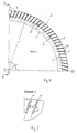
- the cutting edge 2 is double-sided in all embodiments, the bevel angle being 4 °, for example, but also being 3 °.
- the cutting area is toothed, the individual tooth segments 3 being formed by slots 4 which extend at an angle relative to the radius r of 15 ° in the present example from the circumference in the direction of the chamfer 5.
- the beginning of the slot on the circumference of the cutting edge 2 hurries in the direction of rotation of the knife to the end of the slot.
- the slots 4 have different depths in a periodic sequence.
- a maximally long slit 4 is followed by a minimally long one, which in turn is followed by a slit, the depth of which is approximately half the length of the maximally long slit and twice the minimum long slit. This is followed by another minimally long slot, whereupon the period begins again.
- a division of 112 is selected here, the slot depth for a circle diameter of 300 mm being 5, 10 and 20 mm and the slot width 1.2 mm.
- the longest slot 4 ends in the area of the start of the chamfer 5.
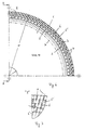
- each slot 4 is provided with two elongated holes 6 arranged one behind the other, which have the same width as the slots 4.
- the angle of inclination of the slot / slot combinations 4, 6 is 15 °
- the slot / slot width is 1.2 mm.
- the slot / slot combinations 4, 6 end at the beginning of the chamfer 5.
- the dash-dotted line 7 indicates the beginning of the cutting area, which is provided with a coating, for example made of titanium carbon nitride.
- the layer thickness can be 1.5 to 4 ⁇ m. Such a coating can of course be implemented in all embodiments.
- the cutting edge 2 is provided with slot / slot combinations 4, 6.
- each slot 6 is aligned with each circumferential slot 4.
- there are two aligned slots 6 ' each aligned with the adjacent slot 6 in Are offset in the direction of the circumference or in the direction of the chamfer 5, so that the end of the elongated hole 6, 6 'and the beginning of the elongated hole 6', 6 lie approximately on the same circular line.
- the angle of inclination of the slot / slot combinations is 4, 6, 6 '15 °
- the slot or slot width is 1.2 mm.
- FIGS. 8 and 9 show an exemplary embodiment which can be referred to as a combination of the exemplary embodiments according to FIGS. 1 and 4.
- a slot 4 of maximum length is provided here, which ends in the region of the start of the chamfer 5.
- This continuous slot 4 is followed by a slot / slot combination 4, 6, the slot having a minimal length and - aligned with this - three slots 6 arranged one behind the other.
- the last elongated hole 6 ends on the same circular line f as the maximally long slot 4.
- This slot / slot combination 4, 6 is followed by a further slot / slot combination, the slot 4 of which has a depth that lies between those of the maximum length slot 4 and the minimum length slot of the previous combination.
- an elongated hole 6 is aligned, the length of which is selected such that it ends on the same circular line f as the maximum long slot 4.
- the slots 4 and elongated holes 6 ending on this circular line f are provided with circular widenings 8 at this end.
- the angle of inclination of the slots or slot / slot combinations is 15 °, as in the other examples, the width of the slots 4 or slots 6 is 1.2 mm.
- a pitch of 200 is selected in the latter example, with a knife diameter of 520 mm.
- these dimensions are only mentioned as examples.
- the ratio of segment width to slot depth> 1.2 should be selected for a given division, segment width being defined in each case as the distance between slots 4 of the same depth.
- FIGS. 1 to 3 an embodiment is shown, which is constructed approximately like the embodiment of FIGS. 1 to 3, but with a knife diameter of 520 mm, but has a division of 200. In this latter example, the maximum long slot extends beyond the beginning of the chamfer 5.
- the cutting principle is more of a cutting grinding due to the geometry of the cutting edge.
- the material e.g. Rubber and the reinforcements (e.g. high-strength steel wire) are removed point by point or line, similar to grinding, but with an extremely narrow, defined cutting edge.
- the cutting process is reinforced by the impulse effect of the segments of the cutting edge.
Landscapes
- Life Sciences & Earth Sciences (AREA)
- Forests & Forestry (AREA)
- Engineering & Computer Science (AREA)
- Mechanical Engineering (AREA)
- Knives (AREA)
- Preliminary Treatment Of Fibers (AREA)
- Food-Manufacturing Devices (AREA)
Applications Claiming Priority (2)
| Application Number | Priority Date | Filing Date | Title |
|---|---|---|---|
| DE19616678A DE19616678C1 (de) | 1996-04-26 | 1996-04-26 | Kreismesser |
| DE19616678 | 1996-04-26 |
Publications (3)
| Publication Number | Publication Date |
|---|---|
| EP0803334A2 true EP0803334A2 (fr) | 1997-10-29 |
| EP0803334A3 EP0803334A3 (fr) | 1998-06-10 |
| EP0803334B1 EP0803334B1 (fr) | 2002-01-09 |
Family
ID=7792506
Family Applications (1)
| Application Number | Title | Priority Date | Filing Date |
|---|---|---|---|
| EP97102546A Expired - Lifetime EP0803334B1 (fr) | 1996-04-26 | 1997-02-18 | Couteau rotatif |
Country Status (3)
| Country | Link |
|---|---|
| EP (1) | EP0803334B1 (fr) |
| AT (1) | ATE211673T1 (fr) |
| DE (1) | DE19616678C1 (fr) |
Families Citing this family (2)
| Publication number | Priority date | Publication date | Assignee | Title |
|---|---|---|---|---|
| IT1302763B1 (it) | 1998-09-07 | 2000-09-29 | Tristano Ciani | Utensile circolare per il taglio di rotoli di carta e simili |
| DE102016005443A1 (de) * | 2016-05-06 | 2017-11-09 | Dipl.lng. S c h i n d l e r & Wagner GmbH & Co KG | Schneidmesser, Vorrichtung zum Aufschneiden von Lebensmittelprodukten mit einem solchen Schneidmesser sowie Verwendung und Verfahren zur Herstellung eines Schneidmessers |
Family Cites Families (11)
| Publication number | Priority date | Publication date | Assignee | Title |
|---|---|---|---|---|
| BE657057A (fr) * | ||||
| US1723843A (en) * | 1926-06-25 | 1929-08-06 | E C Atkins & Company | Fast speed cutter |
| US1975219A (en) * | 1932-08-05 | 1934-10-02 | Seiberling Rubber Co | Cutter for bias cutting machines |
| DE889831C (de) * | 1951-10-27 | 1953-09-14 | Matthias Jans | Hobelkreissaege |
| CH462650A (de) * | 1966-12-09 | 1968-09-15 | Blaettler Wilhelm | Kreissägeblatt, insbesondere zum Sägen von Knochen, Feinfaserholz, Kunststoff oder Nichteisenmetallen, mit über den Kreisumfang mit Abständen voneinander verteilten Sägezähnen |
| US3981216A (en) * | 1973-06-06 | 1976-09-21 | Lemmon & Snoap Co. | Low noise, high speed saw blade |
| FI780507A7 (fi) * | 1978-02-16 | 1979-08-17 | Ahlstroem Oy | Cirkelsaogblad |
| IT1162977B (it) * | 1983-10-31 | 1987-04-01 | Mario Bruno | Mole abrasive a dentatura rinnovabile |
| AT394680B (de) * | 1988-02-03 | 1992-05-25 | Boehler Gmbh | Linien- schneidmesser fuer die bearbeitung von flaechigem material |
| US4854204A (en) * | 1988-03-03 | 1989-08-08 | Am International Incorporated | Rotary knife paper trimmer with long life shearing surfaces for trimming thick and shingled paper products |
| US5078035A (en) * | 1989-08-21 | 1992-01-07 | Diamond Products, Inc. | Circular saw blade |
-
1996
- 1996-04-26 DE DE19616678A patent/DE19616678C1/de not_active Expired - Lifetime
-
1997
- 1997-02-18 AT AT97102546T patent/ATE211673T1/de not_active IP Right Cessation
- 1997-02-18 EP EP97102546A patent/EP0803334B1/fr not_active Expired - Lifetime
Also Published As
| Publication number | Publication date |
|---|---|
| EP0803334B1 (fr) | 2002-01-09 |
| DE19616678C1 (de) | 1997-09-04 |
| ATE211673T1 (de) | 2002-01-15 |
| EP0803334A3 (fr) | 1998-06-10 |
Similar Documents
| Publication | Publication Date | Title |
|---|---|---|
| EP2049295B1 (fr) | Outil de frappe pour l'usinage par enlèvement de copeaux de pièces | |
| DE3300791C2 (de) | Sägeblatt | |
| EP1498203B1 (fr) | Fraise à queue | |
| DE3130828C2 (de) | Werkzeug zum Ausschneiden von Scheiben aus metallischem Material | |
| DE2907360C2 (de) | Gewindeformende Schraube und Rohling zu deren Herstellung | |
| EP2060356B1 (fr) | Lame de scie dotée d'un corps de base et de dents ayant une lame de coupe | |
| EP2848343B1 (fr) | Fraise avec cordon ayant un profilé de dent spécial | |
| DE3532258A1 (de) | Schaftfraeser | |
| DE2848976A1 (de) | Vorrichtung zum maschinellen behandeln der oberflaeche von langhoelzern | |
| EP1031742B1 (fr) | Vis à tête conique | |
| EP1314506B1 (fr) | Outil de taraudage | |
| EP0433484B1 (fr) | Vis autotaraudeuse | |
| DE102017102473B4 (de) | Fräswerkzeug, insbesondere Tannenbaumfräser, und Herstellungsverfahren für ein Fräswerkzeug | |
| EP0523435A1 (fr) | Coupeuse transversale d'une plieuse pour des rotatives à bobines | |
| EP0916771B1 (fr) | Dent de fraisage pour le travail de la terre | |
| DE4127581C2 (fr) | ||
| EP0803334B1 (fr) | Couteau rotatif | |
| EP0519347B1 (fr) | Procédé et dispositif pour fendre ou refendre un produit de sciage rigide | |
| DE10253711A1 (de) | Sägeblatt | |
| DE2233407A1 (de) | Fraeswerkzeug od. dgl | |
| AT404086B (de) | Häckselvorrichtung | |
| DE29607575U1 (de) | Kreismesser | |
| DE102005058536B4 (de) | Schneidwerkzeugsystem, insbesondere zum Verzahnen von Kegelrädern im Einzel-Teil-Verfahren | |
| CH497229A (de) | Bohrer | |
| DE9002555U1 (de) | Kreuzkopfbohrer |
Legal Events
| Date | Code | Title | Description |
|---|---|---|---|
| PUAI | Public reference made under article 153(3) epc to a published international application that has entered the european phase |
Free format text: ORIGINAL CODE: 0009012 |
|
| AK | Designated contracting states |
Kind code of ref document: A2 Designated state(s): AT BE DK FI FR GB IT NL SE |
|
| PUAL | Search report despatched |
Free format text: ORIGINAL CODE: 0009013 |
|
| AK | Designated contracting states |
Kind code of ref document: A3 Designated state(s): AT BE DK FI FR GB IT NL SE |
|
| 17P | Request for examination filed |
Effective date: 19981117 |
|
| 17Q | First examination report despatched |
Effective date: 19991228 |
|
| GRAG | Despatch of communication of intention to grant |
Free format text: ORIGINAL CODE: EPIDOS AGRA |
|
| GRAG | Despatch of communication of intention to grant |
Free format text: ORIGINAL CODE: EPIDOS AGRA |
|
| GRAG | Despatch of communication of intention to grant |
Free format text: ORIGINAL CODE: EPIDOS AGRA |
|
| GRAH | Despatch of communication of intention to grant a patent |
Free format text: ORIGINAL CODE: EPIDOS IGRA |
|
| GRAA | (expected) grant |
Free format text: ORIGINAL CODE: 0009210 |
|
| REG | Reference to a national code |
Ref country code: GB Ref legal event code: IF02 |
|
| AK | Designated contracting states |
Kind code of ref document: B1 Designated state(s): AT BE DK FI FR GB IT NL SE |
|
| REF | Corresponds to: |
Ref document number: 211673 Country of ref document: AT Date of ref document: 20020115 Kind code of ref document: T |
|
| PG25 | Lapsed in a contracting state [announced via postgrant information from national office to epo] |
Ref country code: DK Free format text: LAPSE BECAUSE OF FAILURE TO SUBMIT A TRANSLATION OF THE DESCRIPTION OR TO PAY THE FEE WITHIN THE PRESCRIBED TIME-LIMIT Effective date: 20020409 |
|
| GBT | Gb: translation of ep patent filed (gb section 77(6)(a)/1977) |
Effective date: 20020404 |
|
| ET | Fr: translation filed | ||
| PLBE | No opposition filed within time limit |
Free format text: ORIGINAL CODE: 0009261 |
|
| STAA | Information on the status of an ep patent application or granted ep patent |
Free format text: STATUS: NO OPPOSITION FILED WITHIN TIME LIMIT |
|
| 26N | No opposition filed | ||
| PG25 | Lapsed in a contracting state [announced via postgrant information from national office to epo] |
Ref country code: IT Free format text: LAPSE BECAUSE OF NON-PAYMENT OF DUE FEES Effective date: 20050218 |
|
| PGRI | Patent reinstated in contracting state [announced from national office to epo] |
Ref country code: IT Effective date: 20091201 |
|
| PGFP | Annual fee paid to national office [announced via postgrant information from national office to epo] |
Ref country code: AT Payment date: 20100212 Year of fee payment: 14 |
|
| PGFP | Annual fee paid to national office [announced via postgrant information from national office to epo] |
Ref country code: NL Payment date: 20110216 Year of fee payment: 15 |
|
| PGFP | Annual fee paid to national office [announced via postgrant information from national office to epo] |
Ref country code: BE Payment date: 20110211 Year of fee payment: 15 |
|
| PG25 | Lapsed in a contracting state [announced via postgrant information from national office to epo] |
Ref country code: AT Free format text: LAPSE BECAUSE OF NON-PAYMENT OF DUE FEES Effective date: 20110218 |
|
| PGFP | Annual fee paid to national office [announced via postgrant information from national office to epo] |
Ref country code: FR Payment date: 20120227 Year of fee payment: 16 |
|
| PGFP | Annual fee paid to national office [announced via postgrant information from national office to epo] |
Ref country code: FI Payment date: 20120213 Year of fee payment: 16 Ref country code: GB Payment date: 20120221 Year of fee payment: 16 Ref country code: IT Payment date: 20120227 Year of fee payment: 16 Ref country code: SE Payment date: 20120217 Year of fee payment: 16 |
|
| BERE | Be: lapsed |
Owner name: *INDUNORM HYDRAULIK G.M.B.H. Effective date: 20120228 |
|
| REG | Reference to a national code |
Ref country code: NL Ref legal event code: V1 Effective date: 20120901 |
|
| PG25 | Lapsed in a contracting state [announced via postgrant information from national office to epo] |
Ref country code: BE Free format text: LAPSE BECAUSE OF NON-PAYMENT OF DUE FEES Effective date: 20120228 |
|
| PG25 | Lapsed in a contracting state [announced via postgrant information from national office to epo] |
Ref country code: NL Free format text: LAPSE BECAUSE OF NON-PAYMENT OF DUE FEES Effective date: 20120901 |
|
| REG | Reference to a national code |
Ref country code: SE Ref legal event code: EUG |
|
| GBPC | Gb: european patent ceased through non-payment of renewal fee |
Effective date: 20130218 |
|
| PG25 | Lapsed in a contracting state [announced via postgrant information from national office to epo] |
Ref country code: SE Free format text: LAPSE BECAUSE OF NON-PAYMENT OF DUE FEES Effective date: 20130219 Ref country code: FI Free format text: LAPSE BECAUSE OF NON-PAYMENT OF DUE FEES Effective date: 20130218 |
|
| REG | Reference to a national code |
Ref country code: FR Ref legal event code: ST Effective date: 20131031 |
|
| PG25 | Lapsed in a contracting state [announced via postgrant information from national office to epo] |
Ref country code: IT Free format text: LAPSE BECAUSE OF NON-PAYMENT OF DUE FEES Effective date: 20130218 |
|
| PG25 | Lapsed in a contracting state [announced via postgrant information from national office to epo] |
Ref country code: FR Free format text: LAPSE BECAUSE OF NON-PAYMENT OF DUE FEES Effective date: 20130228 Ref country code: GB Free format text: LAPSE BECAUSE OF NON-PAYMENT OF DUE FEES Effective date: 20130218 |