EP0803343A1 - Auskleidung von leitungen und verfahren zu deren herstellung - Google Patents
Auskleidung von leitungen und verfahren zu deren herstellung Download PDFInfo
- Publication number
- EP0803343A1 EP0803343A1 EP95936758A EP95936758A EP0803343A1 EP 0803343 A1 EP0803343 A1 EP 0803343A1 EP 95936758 A EP95936758 A EP 95936758A EP 95936758 A EP95936758 A EP 95936758A EP 0803343 A1 EP0803343 A1 EP 0803343A1
- Authority
- EP
- European Patent Office
- Prior art keywords
- tubular
- unwoven fabric
- coating layer
- lining material
- stitched
- Prior art date
- Legal status (The legal status is an assumption and is not a legal conclusion. Google has not performed a legal analysis and makes no representation as to the accuracy of the status listed.)
- Granted
Links
- 239000000463 material Substances 0.000 title claims abstract description 66
- 238000004519 manufacturing process Methods 0.000 title claims description 26
- 239000004744 fabric Substances 0.000 claims abstract description 122
- 239000011247 coating layer Substances 0.000 claims abstract description 57
- 229920003002 synthetic resin Polymers 0.000 claims abstract description 21
- 239000000057 synthetic resin Substances 0.000 claims abstract description 21
- 238000005096 rolling process Methods 0.000 claims abstract description 6
- 239000000835 fiber Substances 0.000 claims description 2
- 238000003475 lamination Methods 0.000 claims 1
- 238000001125 extrusion Methods 0.000 description 11
- 239000010410 layer Substances 0.000 description 9
- 229920000728 polyester Polymers 0.000 description 7
- 239000012530 fluid Substances 0.000 description 5
- 230000015572 biosynthetic process Effects 0.000 description 4
- 238000000034 method Methods 0.000 description 4
- 230000003014 reinforcing effect Effects 0.000 description 4
- 229920005989 resin Polymers 0.000 description 4
- 239000011347 resin Substances 0.000 description 4
- 239000004708 Very-low-density polyethylene Substances 0.000 description 3
- 238000004891 communication Methods 0.000 description 3
- 230000006866 deterioration Effects 0.000 description 3
- 230000000694 effects Effects 0.000 description 3
- 239000003673 groundwater Substances 0.000 description 3
- 229920000092 linear low density polyethylene Polymers 0.000 description 3
- 239000004707 linear low-density polyethylene Substances 0.000 description 3
- 229920005992 thermoplastic resin Polymers 0.000 description 3
- 229920001866 very low density polyethylene Polymers 0.000 description 3
- 238000001816 cooling Methods 0.000 description 2
- XLYOFNOQVPJJNP-UHFFFAOYSA-N water Substances O XLYOFNOQVPJJNP-UHFFFAOYSA-N 0.000 description 2
- 239000004952 Polyamide Substances 0.000 description 1
- 239000004760 aramid Substances 0.000 description 1
- 229920003235 aromatic polyamide Polymers 0.000 description 1
- 239000011230 binding agent Substances 0.000 description 1
- 239000011248 coating agent Substances 0.000 description 1
- 238000000576 coating method Methods 0.000 description 1
- 230000000052 comparative effect Effects 0.000 description 1
- 238000010276 construction Methods 0.000 description 1
- 239000000498 cooling water Substances 0.000 description 1
- 230000006837 decompression Effects 0.000 description 1
- 230000003247 decreasing effect Effects 0.000 description 1
- 230000003631 expected effect Effects 0.000 description 1
- 238000003780 insertion Methods 0.000 description 1
- 230000037431 insertion Effects 0.000 description 1
- 238000002156 mixing Methods 0.000 description 1
- 230000035699 permeability Effects 0.000 description 1
- 230000000704 physical effect Effects 0.000 description 1
- 229920002647 polyamide Polymers 0.000 description 1
- 229920000098 polyolefin Polymers 0.000 description 1
- 229920002635 polyurethane Polymers 0.000 description 1
- 239000004814 polyurethane Substances 0.000 description 1
- 229920005749 polyurethane resin Polymers 0.000 description 1
- 238000009751 slip forming Methods 0.000 description 1
- 229920006132 styrene block copolymer Polymers 0.000 description 1
- 229920002725 thermoplastic elastomer Polymers 0.000 description 1
- 229920001187 thermosetting polymer Polymers 0.000 description 1
- 239000002759 woven fabric Substances 0.000 description 1
Images


Classifications
-
- B—PERFORMING OPERATIONS; TRANSPORTING
- B32—LAYERED PRODUCTS
- B32B—LAYERED PRODUCTS, i.e. PRODUCTS BUILT-UP OF STRATA OF FLAT OR NON-FLAT, e.g. CELLULAR OR HONEYCOMB, FORM
- B32B27/00—Layered products comprising a layer of synthetic resin
- B32B27/12—Layered products comprising a layer of synthetic resin next to a fibrous or filamentary layer
-
- B—PERFORMING OPERATIONS; TRANSPORTING
- B29—WORKING OF PLASTICS; WORKING OF SUBSTANCES IN A PLASTIC STATE IN GENERAL
- B29C—SHAPING OR JOINING OF PLASTICS; SHAPING OF MATERIAL IN A PLASTIC STATE, NOT OTHERWISE PROVIDED FOR; AFTER-TREATMENT OF THE SHAPED PRODUCTS, e.g. REPAIRING
- B29C48/00—Extrusion moulding, i.e. expressing the moulding material through a die or nozzle which imparts the desired form; Apparatus therefor
- B29C48/03—Extrusion moulding, i.e. expressing the moulding material through a die or nozzle which imparts the desired form; Apparatus therefor characterised by the shape of the extruded material at extrusion
- B29C48/09—Articles with cross-sections having partially or fully enclosed cavities, e.g. pipes or channels
- B29C48/10—Articles with cross-sections having partially or fully enclosed cavities, e.g. pipes or channels flexible, e.g. blown foils
-
- B—PERFORMING OPERATIONS; TRANSPORTING
- B29—WORKING OF PLASTICS; WORKING OF SUBSTANCES IN A PLASTIC STATE IN GENERAL
- B29C—SHAPING OR JOINING OF PLASTICS; SHAPING OF MATERIAL IN A PLASTIC STATE, NOT OTHERWISE PROVIDED FOR; AFTER-TREATMENT OF THE SHAPED PRODUCTS, e.g. REPAIRING
- B29C48/00—Extrusion moulding, i.e. expressing the moulding material through a die or nozzle which imparts the desired form; Apparatus therefor
- B29C48/15—Extrusion moulding, i.e. expressing the moulding material through a die or nozzle which imparts the desired form; Apparatus therefor incorporating preformed parts or layers, e.g. extrusion moulding around inserts
- B29C48/151—Coating hollow articles
-
- B—PERFORMING OPERATIONS; TRANSPORTING
- B32—LAYERED PRODUCTS
- B32B—LAYERED PRODUCTS, i.e. PRODUCTS BUILT-UP OF STRATA OF FLAT OR NON-FLAT, e.g. CELLULAR OR HONEYCOMB, FORM
- B32B1/00—Layered products having a non-planar shape
- B32B1/08—Tubular products
-
- B—PERFORMING OPERATIONS; TRANSPORTING
- B32—LAYERED PRODUCTS
- B32B—LAYERED PRODUCTS, i.e. PRODUCTS BUILT-UP OF STRATA OF FLAT OR NON-FLAT, e.g. CELLULAR OR HONEYCOMB, FORM
- B32B5/00—Layered products characterised by the non- homogeneity or physical structure, i.e. comprising a fibrous, filamentary, particulate or foam layer; Layered products characterised by having a layer differing constitutionally or physically in different parts
- B32B5/02—Layered products characterised by the non- homogeneity or physical structure, i.e. comprising a fibrous, filamentary, particulate or foam layer; Layered products characterised by having a layer differing constitutionally or physically in different parts characterised by structural features of a fibrous or filamentary layer
- B32B5/022—Non-woven fabric
-
- F—MECHANICAL ENGINEERING; LIGHTING; HEATING; WEAPONS; BLASTING
- F16—ENGINEERING ELEMENTS AND UNITS; GENERAL MEASURES FOR PRODUCING AND MAINTAINING EFFECTIVE FUNCTIONING OF MACHINES OR INSTALLATIONS; THERMAL INSULATION IN GENERAL
- F16L—PIPES; JOINTS OR FITTINGS FOR PIPES; SUPPORTS FOR PIPES, CABLES OR PROTECTIVE TUBING; MEANS FOR THERMAL INSULATION IN GENERAL
- F16L55/00—Devices or appurtenances for use in, or in connection with, pipes or pipe systems
- F16L55/16—Devices for covering leaks in pipes or hoses, e.g. hose-menders
- F16L55/162—Devices for covering leaks in pipes or hoses, e.g. hose-menders from inside the pipe
- F16L55/165—Devices for covering leaks in pipes or hoses, e.g. hose-menders from inside the pipe a pipe or flexible liner being inserted in the damaged section
- F16L55/1656—Devices for covering leaks in pipes or hoses, e.g. hose-menders from inside the pipe a pipe or flexible liner being inserted in the damaged section materials for flexible liners
-
- B—PERFORMING OPERATIONS; TRANSPORTING
- B29—WORKING OF PLASTICS; WORKING OF SUBSTANCES IN A PLASTIC STATE IN GENERAL
- B29C—SHAPING OR JOINING OF PLASTICS; SHAPING OF MATERIAL IN A PLASTIC STATE, NOT OTHERWISE PROVIDED FOR; AFTER-TREATMENT OF THE SHAPED PRODUCTS, e.g. REPAIRING
- B29C53/00—Shaping by bending, folding, twisting, straightening or flattening; Apparatus therefor
- B29C53/36—Bending and joining, e.g. for making hollow articles
- B29C53/38—Bending and joining, e.g. for making hollow articles by bending sheets or strips at right angles to the longitudinal axis of the article being formed and joining the edges
-
- B—PERFORMING OPERATIONS; TRANSPORTING
- B29—WORKING OF PLASTICS; WORKING OF SUBSTANCES IN A PLASTIC STATE IN GENERAL
- B29C—SHAPING OR JOINING OF PLASTICS; SHAPING OF MATERIAL IN A PLASTIC STATE, NOT OTHERWISE PROVIDED FOR; AFTER-TREATMENT OF THE SHAPED PRODUCTS, e.g. REPAIRING
- B29C63/00—Lining or sheathing, i.e. applying preformed layers or sheathings of plastics; Apparatus therefor
-
- B—PERFORMING OPERATIONS; TRANSPORTING
- B32—LAYERED PRODUCTS
- B32B—LAYERED PRODUCTS, i.e. PRODUCTS BUILT-UP OF STRATA OF FLAT OR NON-FLAT, e.g. CELLULAR OR HONEYCOMB, FORM
- B32B2597/00—Tubular articles, e.g. hoses, pipes
-
- Y—GENERAL TAGGING OF NEW TECHNOLOGICAL DEVELOPMENTS; GENERAL TAGGING OF CROSS-SECTIONAL TECHNOLOGIES SPANNING OVER SEVERAL SECTIONS OF THE IPC; TECHNICAL SUBJECTS COVERED BY FORMER USPC CROSS-REFERENCE ART COLLECTIONS [XRACs] AND DIGESTS
- Y10—TECHNICAL SUBJECTS COVERED BY FORMER USPC
- Y10T—TECHNICAL SUBJECTS COVERED BY FORMER US CLASSIFICATION
- Y10T428/00—Stock material or miscellaneous articles
- Y10T428/13—Hollow or container type article [e.g., tube, vase, etc.]
- Y10T428/1352—Polymer or resin containing [i.e., natural or synthetic]
- Y10T428/1362—Textile, fabric, cloth, or pile containing [e.g., web, net, woven, knitted, mesh, nonwoven, matted, etc.]
-
- Y—GENERAL TAGGING OF NEW TECHNOLOGICAL DEVELOPMENTS; GENERAL TAGGING OF CROSS-SECTIONAL TECHNOLOGIES SPANNING OVER SEVERAL SECTIONS OF THE IPC; TECHNICAL SUBJECTS COVERED BY FORMER USPC CROSS-REFERENCE ART COLLECTIONS [XRACs] AND DIGESTS
- Y10—TECHNICAL SUBJECTS COVERED BY FORMER USPC
- Y10T—TECHNICAL SUBJECTS COVERED BY FORMER US CLASSIFICATION
- Y10T428/00—Stock material or miscellaneous articles
- Y10T428/13—Hollow or container type article [e.g., tube, vase, etc.]
- Y10T428/1352—Polymer or resin containing [i.e., natural or synthetic]
- Y10T428/139—Open-ended, self-supporting conduit, cylinder, or tube-type article
-
- Y—GENERAL TAGGING OF NEW TECHNOLOGICAL DEVELOPMENTS; GENERAL TAGGING OF CROSS-SECTIONAL TECHNOLOGIES SPANNING OVER SEVERAL SECTIONS OF THE IPC; TECHNICAL SUBJECTS COVERED BY FORMER USPC CROSS-REFERENCE ART COLLECTIONS [XRACs] AND DIGESTS
- Y10—TECHNICAL SUBJECTS COVERED BY FORMER USPC
- Y10T—TECHNICAL SUBJECTS COVERED BY FORMER US CLASSIFICATION
- Y10T428/00—Stock material or miscellaneous articles
- Y10T428/24—Structurally defined web or sheet [e.g., overall dimension, etc.]
- Y10T428/24033—Structurally defined web or sheet [e.g., overall dimension, etc.] including stitching and discrete fastener[s], coating or bond
- Y10T428/24041—Discontinuous or differential coating, impregnation, or bond
Definitions
- the present invention relates to a lining material, for repairing or reinforcing, for the inner surface of pipelines mainly buried under the ground such as gas conduits, city water pipelines, sewer pipelines, power line, communication line or other laid pipelines.
- the lining material for such pipeline is required to have airtight coating layer for preventing inner fluid from leaking through damaged section of a pipeline or for preventing ground water from infiltrating into the pipeline.
- the lining material is required to have considerably strength for ensuring the inner channel by filling such missing section.
- sheet form unwoven fabric has usually been rolled to form a tube and to form coating layer on it.
- the JP, A, H1-221223 describes a sheet form unwoven fabric which is rolled in a tube form of which both side edges are stitched up and a tubular coating layer is extruded on the outer surface thereof to be integrated therewith. This material is also inserted into a pipeline while turning it inside out to line the inner surface of the pipeline.
- the ribbon may peel off under the pressure of ground water or others infiltrated through a damaged section of the pipeline and the airtightness may be lost.
- the lining material When the lining material is applied to the inner surface of a pipeline, the lining material slightly expands in diameter of the pipeline to open the stitched part and, as the result, to exert a tensile strength breadthwise to the ribbon attached over said stitched part. Consequently, it is highly probable that the ribbon may peel off when an external force such as said ground water is applied.
- a tubular unwoven fabric stitched in tubular form in order to manufacture this lining material is passed through an extruder and a tube of synthetic resin is extruded onto the surface of the tubular unwoven fabric to form the coating layer.
- the pressure is reduced from the inside of the tubular unwoven fabric; however, the air permeability of the stitched part is higher than the other parts in the tubular unwoven fabric as a sheet unwoven fabric is abutted in the stitched part and, moreover, stitched holes of suture are also air-permeable.
- the thinner section may produce pinholes, through which not only the fluid may leak out, but also the tube may begin to burst from a pinhole so as to harm airtightness.
- the present invention is devised considering such inconveniences and has an object of providing a lining material comprising a tubularly stitched unwoven fabric in tubular form and a coating layer formed on the surface thereof, wherein said material ensures the airtightness of the coating layer in said stitched part and composes a sure lining.
- the lining material of the present invention is composed by rolling a sheet unwoven fabric (including felt), stitching mutually both side edges thereof to obtain a tubular unwoven fabric and forming a continuous synthetic resin tubular coating layer on the surface of this tubular unwoven fabric, and is characterized in that the coating layer in said stitched part is thicker than the other sections.
- the manufacturing method of lining material of the invention is characterized by the steps of rolling a sheet unwoven fabric, stitching mutually both side edges thereof to form a tubular unwoven fabric, extruding a continuous synthetic resin tubular body having a thick section at the position corresponding to said stitched part on the surface of this tubular unwoven fabric by using an extruder and decompressing inside said tubular unwoven fabric to adhere said synthetic resin tubular body integrally with the surface of the tubular unwoven fabric.
- Fig. 1 shows a portion of the lining material 1 of the present invention wherein 2 indicates a tubular unwoven fabric composed by rolling a sheet unwoven fabric 3 into a tube and mutually stitching both side edges thereof with a suture 4.
- the unwoven fabric 3 may comprise only unwoven fabric, however, most preferably, a unwoven fabric reinforced in the tube longitudinal direction is used.
- a unwoven fabric reinforced in the tube longitudinal direction is used.
- the lengthwise elongation is reduced while the lining material 1 is manufactured and the longitudinal elongation of stitched holes in the stitched part is avoided so as to prevent physical properties deterioration such as tearing.
- a unwoven fabric 3 wherein a plurality of threads are arranged with a large interval in the tube longitudinal direction on the outside or inside surface or in the thicker section thereof, wherein a fabric loose in weave is integrally adhered may be used.
- This unwoven fabric 3 is rolled into a tubular shape and both side edges thereof are mutually stitched with a suture 4 to form a tubular unwoven fabric 2.
- the stitching structure is not particularly limited, however, it is preferable to stitch so as to confront the end faces of both side edges than to stitch in overlapping with each other because the finishing will be neat when the pipeline is repaired.
- both side edges of a unwoven fabric may be confronted for stitching or they maybe once piled up for stitching and then the end faces of said both side edges are adjusted to be mutually confronted, and either method may be adopted.
- the suture 4 of low elongation thread for preventing the stitched part from opening and the employment of high strength thread may reduce the diameter of thread or stitching needle so as to reduce the size of stitched holes. This permits to prevent the coating layer 5 on the stitched holes from becoming thinner by suction while manufacturing the lining material 1 and to, as the consequence, reduce the total thickness of the thick section 6. By making needle hole smaller, the strength of the unwoven fabric 3 in the stitched part may be maintained so as to allow to use a lower strength unwoven fabric 3.
- tubular unwoven fabric 2 in its tubular lengthwise direction with thread or fabric, its elongation in tubular lengthwise direction may be reduced while manufacturing the lining material 1 so as to permit to avoid the mechanical properties deterioration such as tearing by maintaining the tubular lengthwise strength.
- the generation of pinhole due to needle hole elongation may also be avoided.
- thermosetting resin impregnated in the unwoven fabric 3 it is preferable to use heat-resisting suture in addition to conditions mentioned above.
- a synthetic resin tubular coating layer 5 is continuously formed on the surface of the tubular unwoven fabric 2 manufactured in this way while a section 6 thicker than the other sections is formed on the coating layer 5 of the stitched part of the unwoven fabric 3.
- thermoplastic resin or rubber may be used according to the fluid in the pipeline but it is preferable to use polyolefin, polyurethane, polyester, polyamide or the like.
- the coating layer 5 may also have a laminated structure comprising these resins.
- the inner layer corresponding to the face side of the tubular unwoven fabric 2 one provided for adhering firmly to the unwoven fabric 3 as an adhesion layer, as its exterior layer, one provided with a durability in accordance with the fluid in the pipe and as their intermediate layer, one provided with a function of binder layer may be used in combination.
- this thick section 6 may conveniently be determined from 1.2 to 3.0 times of that of other sections of the coating layer 5. If it is less than 1.2 times, the effect of the invention may not be expected while if it is superior to 3 times, such excessive thickness may harden the coating layer 5 of this stitched part, making difficult to turning the lining material 1 inside out.
- the breadth of the thick section 6 is preferably 1.5 times or more of the stitching width of the suture 4 in the stitched part of the unwoven fabric 3 and less than 1/10 of the circumferential length of the coating layer 5.
- the thick section 6 may be shifted from the stitched part of the unwoven fabric 3 when the lining material 1 is manufactured.
- the dilatation in diameter of the lining material 1 may not be compensated by the elongation of other sections than the thick section 6 to be extended, as the result, if the thick section 6 is extended, stitched part or needle holes in the thick section 6, which are relatively weak in the thick section 6, will be locally extended and the effect of the invention may be unexpected.
- the suture 4 is sufficiently fixed with the material of the thick section 6 to prevent the confronted section and needle holes from being stretched.
- the strength of stitched part is made higher than that of sections other expect stitched part of the thick section 6, a weak strength stitched part would not be stretched as the case for the lining material described in the JP,A, H1-221223 of the Prior Art.
- the tensile strength of the thick section 6 is 1.5 times or more and, preferably, 2.0 times or more than that of the ordinary sections.
- both side edges of the thick section 6 gradually reduce their thickness without forming sudden steps and are continuous with the coating layer 5 other than the thick section 6.
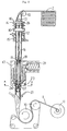
- a tubular unwoven fabric 2 is inserted in a hollow extrusion die 17 and a synthetic resin 21 is tubularly extruded over the outer surface of the tubular unwoven fabric 2 from a resin discharge section 24 of this extrusion die 17 to coat and, at the same time, the tubular unwoven fabric 2 is decompressed by a suction device 14 such as vacuum pump.
- a synthetic resin tubular body 22 is sucked and integrally adhered over the outer surface of the tubular unwoven fabric 2.
- the thick section 6 of the coating layer 5 is manufactured by forming a recess 25 corresponding to the thick section 6 on the resin discharge section 24 and by controlling so that the stitched part is positioned within the recess 25.
- the position of the stitched part of the tubular unwoven fabric 2 to be inserted into the extrusion die 17 is controlled by folding flatly the stitched tubular unwoven fabric 2 with the stitched part beneath and by keeping the fold line of the tubular unwoven fabric 2 in the folded state with a flat plate form jig 16 until just before being inserted into the extrusion die 17.
- the thick section 6 may be formed stably and automatically on the stitched part by defining the mounting position of the flat plate form jig 16 and the recess 25 at the insertion position of the stitched part into the extrusion die 17.
- the lining material 1 shown in Fig. 1 is designed to insert into and line a pipeline by turning inside out its inner and outer surface.
- the manufacturing method mentioned above is also designated to manufacture this lining material 1.
- Example 1 Lining material for lining a pipeline of 300 mm in diameter
- Thickness Thick section 7.5 mm, ordinary section 6.5 mm other than thick section It is thicker than the Example 1 by 0.5 mm because it has not been stretched longitudinally during the manufacturing.
- Thick section width 50 mm It is wider than the Example 1 by 5 mm because it has not been stretched longitudinally during the manufacturing.
- Example 3 Lining material using reinforced unwoven fabric and provided with laminated structure of coating layer
- the suture 4 is firmly fixed with the material of the thick section 6 to prevent the confronted section and needle holes from stretching and, at the same time, the strength of the stitched part is made higher than the other sections expect the thick section 6.
- the stitched part is prevented positive from stretching by elongation of the other sections than the stitched part when the lining material 1 is submitted to expansion in diameter.
- pinholes would not be occurred by the extension of the stitched part when the pipeline is repaired, as it was the case for the lining material described in the JP, A, H1-221223, so as to allow ensuring an airtightness required for the lining material 1.
- the stitched part is prevented from opening and, at the same time, the size of suture or stitching needle may be controlled to reduce the size of the needle hole made by stitching so as to prevent the coating layer 5 above the needle hole from thinning by suction when the lining material 1 is manufactured.
- the strength of the unwoven fabric 3 in the stitched part may be maintained allowing to use a unwoven fabric 3 of lower strength.
- the longitudinal elongation may be controlled during the manufacturing of the lining material 1 allowing to prevent the needle hole of the stitched part from longitudinally stretching and the tube strength in the lengthwise direction may be maintained permitting to prevent the deterioration of mechanical properties such as tearing. Pinhole production due to the elongation of the needle hole may also be restrained.
- the thick section 6 is formed on the coating layer 5 in the stitched part of the tubular unwoven fabric 2, even when the coating layer 5 in the stitched part becomes some thinner by the decompression during the formation of the coating layer 5, pinhole would not be produced because this section is inherently thick, allowing to ensure the airtightness.
- the lining material of the present invention may be manufactured by forming the recess 25 corresponding to the thick section 6 at the discharge section 24 and by controlling the stitched part to be positioned in the recess 25.
- the thick section 6 may be formed stably and automatically on the stitched part.
- Fig. 1 is a cross sectional view of the main section of the lining material according to the present invention.
- Fig. 2 is a central sectional view of the manufacturing machine of the lining material according to the present invention.
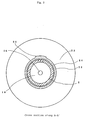
- Fig. 3 is a sectional view along the line A-A' of Fig. 2.
- Fig. 4 is a cross sectional view of the main section of an example of the lining material according to the present invention.
Landscapes
- Engineering & Computer Science (AREA)
- Mechanical Engineering (AREA)
- General Engineering & Computer Science (AREA)
- Textile Engineering (AREA)
- Lining Or Joining Of Plastics Or The Like (AREA)
- Laminated Bodies (AREA)
Applications Claiming Priority (1)
| Application Number | Priority Date | Filing Date | Title |
|---|---|---|---|
| PCT/JP1995/002287 WO1997017187A1 (en) | 1995-11-09 | 1995-11-09 | Conduit lining material and method of manufacturing the same |
Publications (3)
| Publication Number | Publication Date |
|---|---|
| EP0803343A1 true EP0803343A1 (de) | 1997-10-29 |
| EP0803343A4 EP0803343A4 (de) | 2002-09-04 |
| EP0803343B1 EP0803343B1 (de) | 2005-09-07 |
Family
ID=14126438
Family Applications (1)
| Application Number | Title | Priority Date | Filing Date |
|---|---|---|---|
| EP95936758A Expired - Lifetime EP0803343B1 (de) | 1995-11-09 | 1995-11-09 | Auskleidung von leitungen und verfahren zu deren herstellung |
Country Status (4)
| Country | Link |
|---|---|
| US (1) | US5885674A (de) |
| EP (1) | EP0803343B1 (de) |
| DE (1) | DE69534432T2 (de) |
| WO (1) | WO1997017187A1 (de) |
Cited By (2)
| Publication number | Priority date | Publication date | Assignee | Title |
|---|---|---|---|---|
| WO1999011966A1 (en) * | 1997-09-04 | 1999-03-11 | Texon Uk Limited | Renovative pipeliner |
| CN103741340A (zh) * | 2014-01-16 | 2014-04-23 | 上海永利带业股份有限公司 | 一种高强度非开挖管道修复材料及其制造方法 |
Families Citing this family (18)
| Publication number | Priority date | Publication date | Assignee | Title |
|---|---|---|---|---|
| JP3790052B2 (ja) * | 1998-09-25 | 2006-06-28 | 株式会社湘南合成樹脂製作所 | 管ライニング材の製造方法 |
| JP2003526424A (ja) | 2000-03-15 | 2003-09-09 | オスール・エイチエフ | 補綴用吸引スリーブを作る装置及び方法 |
| US8034120B2 (en) | 2002-12-20 | 2011-10-11 | Ossur Hf | Suspension liner system with seal |
| US10322016B2 (en) | 2002-12-20 | 2019-06-18 | Ossur Iceland Ehf | Adjustable seal system, seal component and method for using the same |
| US11523917B2 (en) | 2002-12-20 | 2022-12-13 | Ossur Hf | Suspension liner system with seal |
| US9603726B2 (en) | 2002-12-20 | 2017-03-28 | Ossur Hf | Adjustable seal system, seal component and method for using the same |
| US7041937B2 (en) * | 2003-06-04 | 2006-05-09 | Illinois Tool Works Inc. | Wire feeder operable with lower minimum input voltage requirement |
| US9066820B2 (en) * | 2008-07-18 | 2015-06-30 | Evolution Industries, Inc. | Flexion enhancement member for prosthetic or orthotic liner or sleeve and associated methods |
| US8679194B2 (en) * | 2009-01-21 | 2014-03-25 | Evolution Industries, Inc. | Expulsion liner for prosthetic or orthotic devices and associated methods |
| WO2010085336A1 (en) | 2009-01-21 | 2010-07-29 | Craig Mackenzie | Sealing sheath for prosthetic liner and related methods |
| US8123818B2 (en) * | 2009-03-27 | 2012-02-28 | Ossur Hf | Prosthetic liner with continuous distal end area |
| US8956422B2 (en) | 2011-08-22 | 2015-02-17 | Ossur Hf | Suspension liner with seal component |
| WO2017066038A1 (en) | 2015-10-15 | 2017-04-20 | Ossur Iceland Ehf | Adjustable seal system |
| EP3238667B1 (de) | 2016-04-25 | 2018-10-10 | Össur Iceland EHF | Liner zum überziehen über einen gliedmassenstumpf |
| EP3936087B1 (de) | 2017-11-01 | 2023-07-26 | Össur Iceland EHF | Prothesenschaftsystem |
| US11510793B2 (en) | 2017-11-28 | 2022-11-29 | Ossur Iceland Ehf | Adjustable seal system, seal component and method for using the same |
| EP3727213B1 (de) | 2017-12-20 | 2023-11-15 | Ossur Iceland EHF | Liner mit regionen verschiedener ausdehnung |
| GB2580957B (en) * | 2019-01-31 | 2021-11-03 | W E Rawson Ltd | Improvements relating to pipe liners |
Family Cites Families (3)
| Publication number | Priority date | Publication date | Assignee | Title |
|---|---|---|---|---|
| EP0009402A1 (de) * | 1978-09-22 | 1980-04-02 | Insituform International Inc. | Verfahren zum Herstellen mehrschichtiger Schläuche und hergestellte Mehrschicht-Schläuche |
| JPS6032623A (ja) * | 1983-08-01 | 1985-02-19 | Ashimori Ind Co Ltd | ホ−スの製造方法 |
| JP2721885B2 (ja) * | 1988-02-29 | 1998-03-04 | 芦森工業株式会社 | 管路の内張り材及びその製造方法 |
-
1995
- 1995-11-09 WO PCT/JP1995/002287 patent/WO1997017187A1/ja not_active Ceased
- 1995-11-09 EP EP95936758A patent/EP0803343B1/de not_active Expired - Lifetime
- 1995-11-09 DE DE69534432T patent/DE69534432T2/de not_active Expired - Fee Related
- 1995-11-09 US US08/860,629 patent/US5885674A/en not_active Expired - Fee Related
Cited By (2)
| Publication number | Priority date | Publication date | Assignee | Title |
|---|---|---|---|---|
| WO1999011966A1 (en) * | 1997-09-04 | 1999-03-11 | Texon Uk Limited | Renovative pipeliner |
| CN103741340A (zh) * | 2014-01-16 | 2014-04-23 | 上海永利带业股份有限公司 | 一种高强度非开挖管道修复材料及其制造方法 |
Also Published As
| Publication number | Publication date |
|---|---|
| DE69534432D1 (de) | 2005-10-13 |
| US5885674A (en) | 1999-03-23 |
| EP0803343B1 (de) | 2005-09-07 |
| EP0803343A4 (de) | 2002-09-04 |
| WO1997017187A1 (en) | 1997-05-15 |
| DE69534432T2 (de) | 2006-01-19 |
Similar Documents
| Publication | Publication Date | Title |
|---|---|---|
| US5885674A (en) | Lining material for pipelines and method for manufacturing the same | |
| US6508276B2 (en) | Textile tubing | |
| US9079558B2 (en) | Coated airbag | |
| US5380385A (en) | Process for the manufacture of a flexible polymeric structure by extrusion and the flexible structure manufactured therefrom | |
| US6607797B1 (en) | Textile gas bag material, a protective cushion for an occupant restraint system and a method for producing the textile gas bag material | |
| EP1684967B1 (de) | Längsverstärkte, in-situ ausgehärtete auskleidung | |
| US20100129575A1 (en) | Polyvinyl chloride coated fabrics for use in air bags | |
| JPS61143129A (ja) | 管路の内張り材 | |
| US3817288A (en) | Hose pipes | |
| US20070113971A1 (en) | Longitudinally reinforced cured in place liner and reinforced coating | |
| EP1522781B1 (de) | Armierter Schlauch | |
| US4957792A (en) | Self-molding hose and a continuous vulcanization method | |
| US7763554B2 (en) | Method and device for forming a longitudinal fiber web and for forming a transverse fiber web and for forming a cross fiber web and for forming an airbag | |
| US6129119A (en) | Flexible tube for lining pipes and ducts as well as method and an apparatus for manufacturing thereof | |
| US9239121B1 (en) | Valley shaping reinforcement | |
| US11712857B2 (en) | Method and apparatus for manufacturing dry liners for pipe repair | |
| AU2004253704B2 (en) | Method for continuously producing a coated fabric jacket | |
| KR101755259B1 (ko) | 이중직을 이용한 호스 및, 그 제조방법 | |
| AU2004200054A1 (en) | Unidirectional textile reinforcing sheath capable of being taped onto a mechanical structure to be reinforced | |
| KR20170082478A (ko) | 이중직을 이용한 호스 및, 그 제조방법 | |
| JPH0357846B2 (de) | ||
| JP6484120B2 (ja) | ライニング材およびライニング材の製造方法 | |
| WO1999011966A1 (en) | Renovative pipeliner | |
| JP3317583B2 (ja) | 管路の内張り材及びその製造方法 | |
| WO2006047818A1 (en) | A fabric tube, tube manufacture and tube application |
Legal Events
| Date | Code | Title | Description |
|---|---|---|---|
| PUAI | Public reference made under article 153(3) epc to a published international application that has entered the european phase |
Free format text: ORIGINAL CODE: 0009012 |
|
| AK | Designated contracting states |
Kind code of ref document: A1 Designated state(s): DE FR GB |
|
| 17P | Request for examination filed |
Effective date: 19971017 |
|
| A4 | Supplementary search report drawn up and despatched |
Effective date: 20020723 |
|
| AK | Designated contracting states |
Kind code of ref document: A4 Designated state(s): DE FR GB |
|
| RIC1 | Information provided on ipc code assigned before grant |
Free format text: 7B 29C 63/36 A, 7B 32B 27/12 B, 7B 29C 47/02 B, 7F 16L 55/165 B |
|
| GRAP | Despatch of communication of intention to grant a patent |
Free format text: ORIGINAL CODE: EPIDOSNIGR1 |
|
| GRAS | Grant fee paid |
Free format text: ORIGINAL CODE: EPIDOSNIGR3 |
|
| GRAA | (expected) grant |
Free format text: ORIGINAL CODE: 0009210 |
|
| AK | Designated contracting states |
Kind code of ref document: B1 Designated state(s): DE FR GB |
|
| REG | Reference to a national code |
Ref country code: GB Ref legal event code: FG4D |
|
| REF | Corresponds to: |
Ref document number: 69534432 Country of ref document: DE Date of ref document: 20051013 Kind code of ref document: P |
|
| ET | Fr: translation filed | ||
| PLBE | No opposition filed within time limit |
Free format text: ORIGINAL CODE: 0009261 |
|
| STAA | Information on the status of an ep patent application or granted ep patent |
Free format text: STATUS: NO OPPOSITION FILED WITHIN TIME LIMIT |
|
| 26N | No opposition filed |
Effective date: 20060608 |
|
| PGFP | Annual fee paid to national office [announced via postgrant information from national office to epo] |
Ref country code: GB Payment date: 20071122 Year of fee payment: 13 Ref country code: FR Payment date: 20071116 Year of fee payment: 13 |
|
| PGFP | Annual fee paid to national office [announced via postgrant information from national office to epo] |
Ref country code: DE Payment date: 20071228 Year of fee payment: 13 |
|
| GBPC | Gb: european patent ceased through non-payment of renewal fee |
Effective date: 20081109 |
|
| REG | Reference to a national code |
Ref country code: FR Ref legal event code: ST Effective date: 20090731 |
|
| PG25 | Lapsed in a contracting state [announced via postgrant information from national office to epo] |
Ref country code: DE Free format text: LAPSE BECAUSE OF NON-PAYMENT OF DUE FEES Effective date: 20090603 |
|
| PG25 | Lapsed in a contracting state [announced via postgrant information from national office to epo] |
Ref country code: GB Free format text: LAPSE BECAUSE OF NON-PAYMENT OF DUE FEES Effective date: 20081109 |
|
| PG25 | Lapsed in a contracting state [announced via postgrant information from national office to epo] |
Ref country code: FR Free format text: LAPSE BECAUSE OF NON-PAYMENT OF DUE FEES Effective date: 20081130 |