EP0803353A1 - Procédé pour revêtir deux faces de feuilles de support avec des feuilles et dispositif pour sa mise en oeuvre - Google Patents
Procédé pour revêtir deux faces de feuilles de support avec des feuilles et dispositif pour sa mise en oeuvre Download PDFInfo
- Publication number
- EP0803353A1 EP0803353A1 EP96106355A EP96106355A EP0803353A1 EP 0803353 A1 EP0803353 A1 EP 0803353A1 EP 96106355 A EP96106355 A EP 96106355A EP 96106355 A EP96106355 A EP 96106355A EP 0803353 A1 EP0803353 A1 EP 0803353A1
- Authority
- EP
- European Patent Office
- Prior art keywords
- sheet
- cover sheet
- carrier
- lower cover
- conveyor
- Prior art date
- Legal status (The legal status is an assumption and is not a legal conclusion. Google has not performed a legal analysis and makes no representation as to the accuracy of the status listed.)
- Granted
Links
- 238000000034 method Methods 0.000 title claims abstract description 26
- 230000001154 acute effect Effects 0.000 claims abstract description 13
- 239000003292 glue Substances 0.000 claims abstract description 11
- 238000010030 laminating Methods 0.000 claims description 15
- 238000003475 lamination Methods 0.000 claims description 12
- 238000003825 pressing Methods 0.000 claims description 4
- 238000004026 adhesive bonding Methods 0.000 claims description 3
- 238000010924 continuous production Methods 0.000 claims description 3
- 230000005693 optoelectronics Effects 0.000 claims 1
- 230000032258 transport Effects 0.000 description 3
- 239000000853 adhesive Substances 0.000 description 2
- 230000001070 adhesive effect Effects 0.000 description 2
- 238000012432 intermediate storage Methods 0.000 description 2
- 238000005520 cutting process Methods 0.000 description 1
- 230000007257 malfunction Effects 0.000 description 1
Images

Classifications
-
- B—PERFORMING OPERATIONS; TRANSPORTING
- B32—LAYERED PRODUCTS
- B32B—LAYERED PRODUCTS, i.e. PRODUCTS BUILT-UP OF STRATA OF FLAT OR NON-FLAT, e.g. CELLULAR OR HONEYCOMB, FORM
- B32B37/00—Methods or apparatus for laminating, e.g. by curing or by ultrasonic bonding
- B32B37/02—Methods or apparatus for laminating, e.g. by curing or by ultrasonic bonding characterised by a sequence of laminating steps, e.g. by adding new layers at consecutive laminating stations
-
- B—PERFORMING OPERATIONS; TRANSPORTING
- B32—LAYERED PRODUCTS
- B32B—LAYERED PRODUCTS, i.e. PRODUCTS BUILT-UP OF STRATA OF FLAT OR NON-FLAT, e.g. CELLULAR OR HONEYCOMB, FORM
- B32B37/00—Methods or apparatus for laminating, e.g. by curing or by ultrasonic bonding
- B32B37/14—Methods or apparatus for laminating, e.g. by curing or by ultrasonic bonding characterised by the properties of the layers
- B32B37/16—Methods or apparatus for laminating, e.g. by curing or by ultrasonic bonding characterised by the properties of the layers with all layers existing as coherent layers before laminating
- B32B37/18—Methods or apparatus for laminating, e.g. by curing or by ultrasonic bonding characterised by the properties of the layers with all layers existing as coherent layers before laminating involving the assembly of discrete sheets or panels only
-
- B—PERFORMING OPERATIONS; TRANSPORTING
- B32—LAYERED PRODUCTS
- B32B—LAYERED PRODUCTS, i.e. PRODUCTS BUILT-UP OF STRATA OF FLAT OR NON-FLAT, e.g. CELLULAR OR HONEYCOMB, FORM
- B32B38/00—Ancillary operations in connection with laminating processes
- B32B38/18—Handling of layers or the laminate
- B32B38/1825—Handling of layers or the laminate characterised by the control or constructional features of devices for tensioning, stretching or registration
- B32B38/1833—Positioning, e.g. registration or centering
- B32B38/1841—Positioning, e.g. registration or centering during laying up
Definitions
- the invention relates to a method for laminating a carrier sheet on both sides, each with a cover sheet, the sheets to be connected, which are provided with glue, being integrally connected to one another under pressure.
- the invention relates to a device for performing the method.
- One- and two-sided lamination of a carrier sheet with a cover sheet is known. With one-sided lamination, the adhesive required for bonding is applied to the top of the carrier sheet in a glue unit. A subsequent pressing device then connects the two arches.
- the invention has for its object to provide a method that completely eliminates the disadvantages associated with the prior art and also has the advantage of better performance with high quality.
- a device according to the invention is to be created with which the method according to the invention can be carried out.
- the process according to the invention enables double-sided lamination of carrier sheets in a continuous continuous process. If necessary, however, the process only allows one-sided lamination. In this case, the cover sheet on the side of the carrier sheet that is not to be laminated is simply omitted.
- the lower cover sheet is fed to the support sheet at an acute angle.
- the lower cover sheet can be gradually laminated onto the underside of the support sheet so that there are no air pockets.
- the upper cover sheet is fed to the support sheet at an acute angle ( claim 3 ).
- the upper cover sheet is first connected in the direction of flow by lamination to the support sheet before the lower cover sheet is fed to the support sheet and connected to it by lamination ( claim 4 ).
- the upper sides of the carrier sheet and the cover sheet coming from below are provided with glue on its upper side ( claim 5 ).
- the support sheet and the cover sheet are each provided in a horizontal position with glue before the cover sheet is moved on a path which is at an acute angle to the transport plane of the support sheet. ( Claim 6 ). This allows the glue to be applied quickly and without dripping before it is laminated onto the carrier sheet.
- At least the lower cover sheet with respect to the support sheet is aligned transversely and / or in the direction of passage of the support sheet edge and fit. This eliminates the need for reworking, such as cutting the edges of the double-sided backing sheet.
- ACCORDING to claim 8 is transported to the lower covering sheet by vacuum for the purpose of aligning independent of the support sheet.
- the carrier sheet already laminated with an upper cover sheet is stopped with the lower cover sheet and aligned transversely with respect to the conveying direction before it is fed and laminated precisely before the cover sheet is aligned and connected to the underside of the support sheet.
- it is up to you to specify coordinates or planes in which the carrier sheet is arranged, to which the cover sheet to be concealed, in particular the lower cover sheet, is fed with a precise fit.
- the position points of the carrier sheet laminated on one side can thereby be entered into a control and then, based on these values, the lower cover sheet is fed to the underside of the carrier sheet laminated on one side with an exact fit and edge, and can be connected to it by lamination ( claim 9 ).
- This claim describes a device according to the invention, in which a motor-driven conveyor is arranged below the conveyor track for the support sheet, the conveyor track of which runs at an acute angle to the conveyor track of the support sheet, on which the lower cover sheet passes through an acute angle motor-driven conveyor is brought up.
- the motor-driven conveyor for the carrier sheet is assigned at least one, but preferably two, spaced-apart, motor-controlled alignment devices, by means of which the carrier sheet can be moved orthogonally to its conveying direction and thus aligned.
- the carrier sheet laminated on one side thus runs, driven by the conveyor on which it is located, up to the stop, whereupon the drive for the conveyor device is stopped, while the lower cover sheet is also moved by its conveyor to the stop assigned to it, whereupon the drive for this conveyor is also stopped.
- the lateral alignment of the carrier sheet laminated on one side is carried out by the alignment devices, followed by the transverse alignment of the lower cover sheet and the feeding of the aligned cover sheet to the underside of the carrier sheet, whereupon the carrier sheet already laminated on one side is connected to the lower cover sheet by laminating in a printing device .
- the motor, z. B. pneumatic and / or electric drives, the alignment device, the stops and the suction device with their motor drives each in a sequential control system that controls the sensible sequence of movements of the conveyor, the stops and the suction devices and the gluing devices.
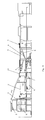
- a stack of carrier sheets 1 is arranged in a frame, from which the carrier sheets 1 are individually transported in the X direction via a motor-driven conveyor 2.
- the carrier sheet 1 laminated on its upper side with a cover sheet 3 is transported further in the X direction by a motor-driven conveyor 5 designed as a belt conveyor.
- a stack of lower cover sheets 6 is arranged, which are also transported in a horizontal direction in the direction X via a motor-driven conveyor 7 until they reach a motor-driven conveyor 8 on which the lower cover sheets 6 are at an acute angle ⁇ to Conveyor path of conveyor 5 can be conveyed on.
- the carrier sheet 1 laminated with the upper cover sheet 3 is conveyed into a second laminating station 9 via the conveyor 5.
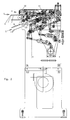
- the carrier sheet 1, which is laminated on one side, is then taken over by the conveyor 5 with the aid of a vacuum suction belt 10 and transported to a rotatably mounted stop 11 and thereby aligned in the conveying direction X.
- the carrier sheet 1 laminated on one side is aligned orthogonally to the conveying direction X, that is to the side, by two variably adjustable side pushers 12. Only one of these side bumpers 12 can be seen in FIG. 2. On the opposite side, such a side bumper is arranged.
- the side pushers 12 are driven by a motor, for example by piston-cylinder units to be acted upon alternately hydraulically or pneumatically with pressure medium pressure, by linear motors or the like.
- the stop 11 can be folded up or rotated by motor in the dot-dash position.
- the lower cover sheet 6 is glued on its side facing the underside of the carrier sheet 1 laminated on one side and likewise fed to the second laminating station 9 by the motor-driven conveyor 8.
- a likewise motor-driven conveyor 13 takes over the glued lower cover sheet 6 and transports it to a rotatably mounted stop 14.
- the lower cover sheet 6 is thereby aligned in its transport direction Z.
- This suction device 15 has a plurality of suction cups of the same size, arranged laterally on a straight line running orthogonally to the conveying direction Z, each of which is connected to a supply pipe 16 via a pipe connection (not shown in detail), which is connected to a motor-driven suction source, not shown, in particular a vacuum pump is connected.
- the lower cover sheet 6 is now moved laterally by the suction device 15 and with the aid of a motor drive, for example a stepping motor, until the correct position in relation to the support sheet 1 is recognized, such that the lower cover sheet 6 fits and comes to lie precisely with respect to the underside of the carrier sheet 1 which has already been laminated on one side at the top.
- a motor drive for example a stepping motor
- the stop 14 is controlled in the open position and the suctioned lower cover sheet 6 is transported to the carrier sheet stop 11 by a slide movement.
- the rotatably mounted stop 14 is moved away and the lower cover sheet 6 is transported further by a clock roller 17, namely to two adjustable press rollers 18, which connect the one-sided laminated carrier sheet 1 to the lower cover sheet 6 by lamination.
- the drives and movements are included in a suitable control and can also be operated remotely from a control panel (not shown).
- the device can also be used only for one-sided lamination of carrier sheets 1.
Landscapes
- Folding Of Thin Sheet-Like Materials, Special Discharging Devices, And Others (AREA)
- Making Paper Articles (AREA)
- Wrappers (AREA)
- Lining Or Joining Of Plastics Or The Like (AREA)
- Vehicle Interior And Exterior Ornaments, Soundproofing, And Insulation (AREA)
Priority Applications (5)
| Application Number | Priority Date | Filing Date | Title |
|---|---|---|---|
| ES96106355T ES2141413T3 (es) | 1996-04-23 | 1996-04-23 | Procedimiento para forrar por ambas caras hojas de soporte con una hoja de recubrimiento por cada cara, e instalacion para realizar el procedimiento. |
| AT96106355T ATE188648T1 (de) | 1996-04-23 | 1996-04-23 | Verfahren zum beidseitigen kaschieren von trägerbögen mit je einem deckbogen und einrichtung zum durchführen des verfahrens |
| DE59604170T DE59604170D1 (de) | 1996-04-23 | 1996-04-23 | Verfahren zum beidseitigen Kaschieren von Trägerbögen mit je einem Deckbogen und Einrichtung zum Durchführen des Verfahrens |
| EP96106355A EP0803353B1 (fr) | 1996-04-23 | 1996-04-23 | Procédé pour revêtir deux faces de feuilles de support avec des feuilles et dispositif pour sa mise en oeuvre |
| US08/838,250 US5944936A (en) | 1996-04-23 | 1997-04-17 | Process for laminating a cover sheet on each side of a blank and an apparatus to accomplish the process |
Applications Claiming Priority (1)
| Application Number | Priority Date | Filing Date | Title |
|---|---|---|---|
| EP96106355A EP0803353B1 (fr) | 1996-04-23 | 1996-04-23 | Procédé pour revêtir deux faces de feuilles de support avec des feuilles et dispositif pour sa mise en oeuvre |
Publications (2)
| Publication Number | Publication Date |
|---|---|
| EP0803353A1 true EP0803353A1 (fr) | 1997-10-29 |
| EP0803353B1 EP0803353B1 (fr) | 2000-01-12 |
Family
ID=8222702
Family Applications (1)
| Application Number | Title | Priority Date | Filing Date |
|---|---|---|---|
| EP96106355A Expired - Lifetime EP0803353B1 (fr) | 1996-04-23 | 1996-04-23 | Procédé pour revêtir deux faces de feuilles de support avec des feuilles et dispositif pour sa mise en oeuvre |
Country Status (5)
| Country | Link |
|---|---|
| US (1) | US5944936A (fr) |
| EP (1) | EP0803353B1 (fr) |
| AT (1) | ATE188648T1 (fr) |
| DE (1) | DE59604170D1 (fr) |
| ES (1) | ES2141413T3 (fr) |
Cited By (3)
| Publication number | Priority date | Publication date | Assignee | Title |
|---|---|---|---|---|
| DE10254504A1 (de) * | 2002-11-22 | 2004-06-09 | Tünkers Maschinenbau Gmbh | Verfahren zum Kaschieren von zwei oder mehreren gleichen oder unterschiedlichen Bögen, und Vorrichtung zum Durchführen des Verfahrens |
| DE102007034106A1 (de) * | 2007-07-21 | 2009-01-22 | Tünkers Maschinenbau Gmbh | Verfahren zum beidseitigen Kaschieren eines Trägerbogens mit je einem Deckbogen im Durchlaufverfahren und Einrichtung zum Durchführen dieses Verfahrens |
| CN101214670B (zh) * | 2008-01-17 | 2012-02-01 | 无锡市盛金机械有限公司 | 贴面机 |
Families Citing this family (4)
| Publication number | Priority date | Publication date | Assignee | Title |
|---|---|---|---|---|
| DE10358547B3 (de) * | 2003-12-15 | 2005-06-16 | Tünkers Maschinenbau Gmbh | Kaschiermaschine |
| US7124799B2 (en) * | 2004-07-27 | 2006-10-24 | Picture Rich Llc | Lamination apparatus and method of use |
| DE102005015295A1 (de) * | 2005-04-01 | 2006-10-19 | Billhöfer Maschinenfabrik GmbH & Co. KG | Vorrichtung und Verfahren zum Beschichten eines metallischen Trägermaterials |
| DE202009014367U1 (de) | 2009-10-23 | 2010-01-14 | Tünkers Maschinenbau Gmbh | Motorisch angetriebene Bogenkaschiereinrichtung |
Citations (5)
| Publication number | Priority date | Publication date | Assignee | Title |
|---|---|---|---|---|
| DE1511291A1 (de) * | 1966-03-26 | 1969-06-19 | Prakma Maschinenfabrik Gmbh | Verfahren und Vorrichtung zum Kaschieren von Bogen auf Bogen |
| DE2945442A1 (de) * | 1979-11-10 | 1981-05-21 | G. Siempelkamp Gmbh & Co, 4150 Krefeld | Vorrichtung zum auflegen von folienabschnitten auf die oberseite und/oder die unterseite von holzwerkstoffplatten |
| US4288274A (en) * | 1978-12-22 | 1981-09-08 | G. Siempelkamp Gmbh & Co. | Method of and apparatus for applying veneer foils to a board |
| US4624719A (en) * | 1983-04-30 | 1986-11-25 | Tuenkers Maschinenbau Gmbh | Process and device for laminating of sheet to sheet |
| DE4216691A1 (de) * | 1992-05-20 | 1993-11-25 | Dieffenbacher Gmbh Maschf | Vorrichtung zum Belegen von Platten |
Family Cites Families (3)
| Publication number | Priority date | Publication date | Assignee | Title |
|---|---|---|---|---|
| SE433926B (sv) * | 1981-05-04 | 1984-06-25 | Elvsborg Pack Ab | Maskin for kaschering av tva eller flera ark till ett flerskiktsark |
| DE3502608A1 (de) * | 1985-01-26 | 1986-08-14 | Herbert Kannegiesser Gmbh + Co, 4973 Vlotho | Verfahren und vorrichtung zum verkleben von textilen flaechengebilden |
| US5316609A (en) * | 1992-11-18 | 1994-05-31 | Pro-Tech Engineering Co., Inc. | Encapsulating laminator |
-
1996
- 1996-04-23 DE DE59604170T patent/DE59604170D1/de not_active Expired - Lifetime
- 1996-04-23 EP EP96106355A patent/EP0803353B1/fr not_active Expired - Lifetime
- 1996-04-23 AT AT96106355T patent/ATE188648T1/de not_active IP Right Cessation
- 1996-04-23 ES ES96106355T patent/ES2141413T3/es not_active Expired - Lifetime
-
1997
- 1997-04-17 US US08/838,250 patent/US5944936A/en not_active Expired - Lifetime
Patent Citations (5)
| Publication number | Priority date | Publication date | Assignee | Title |
|---|---|---|---|---|
| DE1511291A1 (de) * | 1966-03-26 | 1969-06-19 | Prakma Maschinenfabrik Gmbh | Verfahren und Vorrichtung zum Kaschieren von Bogen auf Bogen |
| US4288274A (en) * | 1978-12-22 | 1981-09-08 | G. Siempelkamp Gmbh & Co. | Method of and apparatus for applying veneer foils to a board |
| DE2945442A1 (de) * | 1979-11-10 | 1981-05-21 | G. Siempelkamp Gmbh & Co, 4150 Krefeld | Vorrichtung zum auflegen von folienabschnitten auf die oberseite und/oder die unterseite von holzwerkstoffplatten |
| US4624719A (en) * | 1983-04-30 | 1986-11-25 | Tuenkers Maschinenbau Gmbh | Process and device for laminating of sheet to sheet |
| DE4216691A1 (de) * | 1992-05-20 | 1993-11-25 | Dieffenbacher Gmbh Maschf | Vorrichtung zum Belegen von Platten |
Cited By (4)
| Publication number | Priority date | Publication date | Assignee | Title |
|---|---|---|---|---|
| DE10254504A1 (de) * | 2002-11-22 | 2004-06-09 | Tünkers Maschinenbau Gmbh | Verfahren zum Kaschieren von zwei oder mehreren gleichen oder unterschiedlichen Bögen, und Vorrichtung zum Durchführen des Verfahrens |
| DE10254504B4 (de) * | 2002-11-22 | 2006-02-16 | Tünkers Maschinenbau Gmbh | Verfahren zum Kaschieren von zwei oder mehreren gleichen oder unterschiedlichen Bögen, und Vorrichtung zum Durchführen des Verfahrens |
| DE102007034106A1 (de) * | 2007-07-21 | 2009-01-22 | Tünkers Maschinenbau Gmbh | Verfahren zum beidseitigen Kaschieren eines Trägerbogens mit je einem Deckbogen im Durchlaufverfahren und Einrichtung zum Durchführen dieses Verfahrens |
| CN101214670B (zh) * | 2008-01-17 | 2012-02-01 | 无锡市盛金机械有限公司 | 贴面机 |
Also Published As
| Publication number | Publication date |
|---|---|
| ES2141413T3 (es) | 2000-03-16 |
| DE59604170D1 (de) | 2000-02-17 |
| EP0803353B1 (fr) | 2000-01-12 |
| ATE188648T1 (de) | 2000-01-15 |
| US5944936A (en) | 1999-08-31 |
Similar Documents
| Publication | Publication Date | Title |
|---|---|---|
| EP2243619B1 (fr) | Dispositif et procédé destinés au revêtement de pièces à usiner | |
| EP2508353A2 (fr) | Machine destinée à la fabrication de livres, notamment livres photo et/ou livres illustrés | |
| EP0860253A2 (fr) | Procédé et appareil pour la fabrication de portes multi-couches | |
| DE4141767A1 (de) | Verfahren und anordnung zum herstellen von buechern und broschueren | |
| EP2517892B1 (fr) | Dispositif et procédé de fabrication d'un bloc de livre relié présentant une bande à onglets ou une couverture | |
| DE69903307T2 (de) | Vorrichtung mit pneumatischen fingerelementen zum aufrichten von faltschachteln | |
| EP0803353B1 (fr) | Procédé pour revêtir deux faces de feuilles de support avec des feuilles et dispositif pour sa mise en oeuvre | |
| EP1577273B1 (fr) | Dispositif et procédé pour couper du verre feuilleté selon un contour quelconque | |
| DE69713371T2 (de) | Vorrichtung zum miteinanderverbinden von flachen gegenständen | |
| WO1982001847A1 (fr) | Procede et dispositif pour coller ensemble des panneaux | |
| DE10157833A1 (de) | Verbundglasschneidanlage | |
| EP4034390B1 (fr) | Dispositif et procédé de fabrication automatique de couvertures de reliures de livres et/ou de couvertures de boîtes | |
| EP3790715B1 (fr) | Dispositif et méthode de placage de chant | |
| EP0489681B1 (fr) | Procédé et dispositif pour déplacer des pièces en forme de bandes ou de panneaux, empilés et juxtaposés sur une surface de support à faible coefficient de frottement | |
| EP0175795B1 (fr) | Dispositif de laminage | |
| EP1287955B1 (fr) | Installation pour le traitement automatique de panneaux en bois et/ou en ersatz de bois | |
| DE10047385C2 (de) | Verfahren und Vorrichtung zur Bearbeitung von fortlaufend bewegten Werkstücken | |
| DE19515087B4 (de) | Maschine zur kontinuierlichen Beschichtung von Paneelen mit Laminaten | |
| EP1990152A1 (fr) | Dispositif et procédé de collage de bordures | |
| DE10254504B4 (de) | Verfahren zum Kaschieren von zwei oder mehreren gleichen oder unterschiedlichen Bögen, und Vorrichtung zum Durchführen des Verfahrens | |
| DE3713773C2 (de) | Verfahren und Vorrichtung zum kontinuierlichen Anleimen von Furnierstreifen auf Kanten von plattenförmigen Werkstücken | |
| DE10358547B3 (de) | Kaschiermaschine | |
| EP1201417A2 (fr) | Procédé et dispositif de préparation de flans en carton | |
| EP3365147A1 (fr) | Procédé permettant d'enturer des feuilles de contreplaqué | |
| DE19839923C2 (de) | Vorrichtung zur Abnahme von Folien von einem Folienstapel in einer Stapelstation und zur Ablage der abgenommenen Folien in einer Zusammenlegestation |
Legal Events
| Date | Code | Title | Description |
|---|---|---|---|
| PUAI | Public reference made under article 153(3) epc to a published international application that has entered the european phase |
Free format text: ORIGINAL CODE: 0009012 |
|
| 17P | Request for examination filed |
Effective date: 19960712 |
|
| AK | Designated contracting states |
Kind code of ref document: A1 Designated state(s): AT CH DE ES FR GB IT LI NL SE |
|
| GRAG | Despatch of communication of intention to grant |
Free format text: ORIGINAL CODE: EPIDOS AGRA |
|
| GRAG | Despatch of communication of intention to grant |
Free format text: ORIGINAL CODE: EPIDOS AGRA |
|
| GRAH | Despatch of communication of intention to grant a patent |
Free format text: ORIGINAL CODE: EPIDOS IGRA |
|
| 17Q | First examination report despatched |
Effective date: 19990618 |
|
| GRAH | Despatch of communication of intention to grant a patent |
Free format text: ORIGINAL CODE: EPIDOS IGRA |
|
| GRAA | (expected) grant |
Free format text: ORIGINAL CODE: 0009210 |
|
| ITF | It: translation for a ep patent filed | ||
| AK | Designated contracting states |
Kind code of ref document: B1 Designated state(s): AT CH DE ES FR GB IT LI NL SE |
|
| PG25 | Lapsed in a contracting state [announced via postgrant information from national office to epo] |
Ref country code: NL Free format text: LAPSE BECAUSE OF FAILURE TO SUBMIT A TRANSLATION OF THE DESCRIPTION OR TO PAY THE FEE WITHIN THE PRESCRIBED TIME-LIMIT Effective date: 20000112 |
|
| REF | Corresponds to: |
Ref document number: 188648 Country of ref document: AT Date of ref document: 20000115 Kind code of ref document: T |
|
| REG | Reference to a national code |
Ref country code: CH Ref legal event code: NV Representative=s name: ISLER & PEDRAZZINI AG Ref country code: CH Ref legal event code: EP |
|
| REF | Corresponds to: |
Ref document number: 59604170 Country of ref document: DE Date of ref document: 20000217 |
|
| REG | Reference to a national code |
Ref country code: ES Ref legal event code: FG2A Ref document number: 2141413 Country of ref document: ES Kind code of ref document: T3 |
|
| ET | Fr: translation filed | ||
| PG25 | Lapsed in a contracting state [announced via postgrant information from national office to epo] |
Ref country code: AT Free format text: LAPSE BECAUSE OF NON-PAYMENT OF DUE FEES Effective date: 20000423 |
|
| GBT | Gb: translation of ep patent filed (gb section 77(6)(a)/1977) |
Effective date: 20000418 |
|
| NLV1 | Nl: lapsed or annulled due to failure to fulfill the requirements of art. 29p and 29m of the patents act | ||
| PLBE | No opposition filed within time limit |
Free format text: ORIGINAL CODE: 0009261 |
|
| STAA | Information on the status of an ep patent application or granted ep patent |
Free format text: STATUS: NO OPPOSITION FILED WITHIN TIME LIMIT |
|
| 26N | No opposition filed | ||
| REG | Reference to a national code |
Ref country code: GB Ref legal event code: IF02 |
|
| REG | Reference to a national code |
Ref country code: CH Ref legal event code: PCAR Free format text: ISLER & PEDRAZZINI AG;POSTFACH 1772;8027 ZUERICH (CH) |
|
| PGFP | Annual fee paid to national office [announced via postgrant information from national office to epo] |
Ref country code: ES Payment date: 20090508 Year of fee payment: 14 |
|
| PGFP | Annual fee paid to national office [announced via postgrant information from national office to epo] |
Ref country code: SE Payment date: 20090407 Year of fee payment: 14 Ref country code: IT Payment date: 20090421 Year of fee payment: 14 |
|
| PGFP | Annual fee paid to national office [announced via postgrant information from national office to epo] |
Ref country code: CH Payment date: 20090416 Year of fee payment: 14 |
|
| PGFP | Annual fee paid to national office [announced via postgrant information from national office to epo] |
Ref country code: GB Payment date: 20090422 Year of fee payment: 14 |
|
| EUG | Se: european patent has lapsed | ||
| REG | Reference to a national code |
Ref country code: CH Ref legal event code: PL |
|
| GBPC | Gb: european patent ceased through non-payment of renewal fee |
Effective date: 20100423 |
|
| PG25 | Lapsed in a contracting state [announced via postgrant information from national office to epo] |
Ref country code: LI Free format text: LAPSE BECAUSE OF NON-PAYMENT OF DUE FEES Effective date: 20100430 Ref country code: CH Free format text: LAPSE BECAUSE OF NON-PAYMENT OF DUE FEES Effective date: 20100430 |
|
| PG25 | Lapsed in a contracting state [announced via postgrant information from national office to epo] |
Ref country code: IT Free format text: LAPSE BECAUSE OF NON-PAYMENT OF DUE FEES Effective date: 20100423 Ref country code: GB Free format text: LAPSE BECAUSE OF NON-PAYMENT OF DUE FEES Effective date: 20100423 |
|
| REG | Reference to a national code |
Ref country code: ES Ref legal event code: FD2A Effective date: 20110715 |
|
| PG25 | Lapsed in a contracting state [announced via postgrant information from national office to epo] |
Ref country code: ES Free format text: LAPSE BECAUSE OF NON-PAYMENT OF DUE FEES Effective date: 20110705 |
|
| PG25 | Lapsed in a contracting state [announced via postgrant information from national office to epo] |
Ref country code: ES Free format text: LAPSE BECAUSE OF NON-PAYMENT OF DUE FEES Effective date: 20100424 |
|
| PGFP | Annual fee paid to national office [announced via postgrant information from national office to epo] |
Ref country code: DE Payment date: 20120425 Year of fee payment: 17 |
|
| PGFP | Annual fee paid to national office [announced via postgrant information from national office to epo] |
Ref country code: FR Payment date: 20120504 Year of fee payment: 17 |
|
| PG25 | Lapsed in a contracting state [announced via postgrant information from national office to epo] |
Ref country code: SE Free format text: LAPSE BECAUSE OF NON-PAYMENT OF DUE FEES Effective date: 20100424 |
|
| REG | Reference to a national code |
Ref country code: DE Ref legal event code: R119 Ref document number: 59604170 Country of ref document: DE |
|
| PG25 | Lapsed in a contracting state [announced via postgrant information from national office to epo] |
Ref country code: DE Free format text: LAPSE BECAUSE OF NON-PAYMENT OF DUE FEES Effective date: 20131101 |
|
| REG | Reference to a national code |
Ref country code: FR Ref legal event code: ST Effective date: 20131231 |
|
| PG25 | Lapsed in a contracting state [announced via postgrant information from national office to epo] |
Ref country code: FR Free format text: LAPSE BECAUSE OF NON-PAYMENT OF DUE FEES Effective date: 20130430 |
|
| REG | Reference to a national code |
Ref country code: DE Ref legal event code: R079 Ref document number: 59604170 Country of ref document: DE Free format text: PREVIOUS MAIN CLASS: B32B0031060000 Ipc: B32B0037000000 |
|
| REG | Reference to a national code |
Ref country code: DE Ref legal event code: R119 Ref document number: 59604170 Country of ref document: DE Effective date: 20131101 Ref country code: DE Ref legal event code: R079 Ref document number: 59604170 Country of ref document: DE Free format text: PREVIOUS MAIN CLASS: B32B0031060000 Ipc: B32B0037000000 Effective date: 20141208 |