EP0803384B1 - Dispositif pour limiter le mouvement pendulaire d'un essieu rigide d'un véhicule utilitaire, notamment d'un tracteur agricole - Google Patents
Dispositif pour limiter le mouvement pendulaire d'un essieu rigide d'un véhicule utilitaire, notamment d'un tracteur agricole Download PDFInfo
- Publication number
- EP0803384B1 EP0803384B1 EP97105504A EP97105504A EP0803384B1 EP 0803384 B1 EP0803384 B1 EP 0803384B1 EP 97105504 A EP97105504 A EP 97105504A EP 97105504 A EP97105504 A EP 97105504A EP 0803384 B1 EP0803384 B1 EP 0803384B1
- Authority
- EP
- European Patent Office
- Prior art keywords
- rigid axis
- hydraulic cylinder
- rigid
- rigid axle
- chassis
- Prior art date
- Legal status (The legal status is an assumption and is not a legal conclusion. Google has not performed a legal analysis and makes no representation as to the accuracy of the status listed.)
- Expired - Lifetime
Links
- 230000008878 coupling Effects 0.000 claims 4
- 238000010168 coupling process Methods 0.000 claims 4
- 238000005859 coupling reaction Methods 0.000 claims 4
- 238000009313 farming Methods 0.000 claims 1
- 239000000725 suspension Substances 0.000 description 5
- 230000007935 neutral effect Effects 0.000 description 2
- 230000010355 oscillation Effects 0.000 description 2
- 230000006835 compression Effects 0.000 description 1
- 238000007906 compression Methods 0.000 description 1
- 239000012530 fluid Substances 0.000 description 1
Images

Classifications
-
- B—PERFORMING OPERATIONS; TRANSPORTING
- B60—VEHICLES IN GENERAL
- B60G—VEHICLE SUSPENSION ARRANGEMENTS
- B60G7/00—Pivoted suspension arms; Accessories thereof
- B60G7/04—Buffer means for limiting movement of arms
-
- B—PERFORMING OPERATIONS; TRANSPORTING
- B60—VEHICLES IN GENERAL
- B60G—VEHICLE SUSPENSION ARRANGEMENTS
- B60G17/00—Resilient suspensions having means for adjusting the spring or vibration-damper characteristics, for regulating the distance between a supporting surface and a sprung part of vehicle or for locking suspension during use to meet varying vehicular or surface conditions, e.g. due to speed or load
- B60G17/005—Suspension locking arrangements
-
- B—PERFORMING OPERATIONS; TRANSPORTING
- B60—VEHICLES IN GENERAL
- B60G—VEHICLE SUSPENSION ARRANGEMENTS
- B60G9/00—Resilient suspensions of a rigid axle or axle housing for two or more wheels
- B60G9/02—Resilient suspensions of a rigid axle or axle housing for two or more wheels the axle or housing being pivotally mounted on the vehicle, e.g. the pivotal axis being parallel to the longitudinal axis of the vehicle
-
- B—PERFORMING OPERATIONS; TRANSPORTING
- B60—VEHICLES IN GENERAL
- B60G—VEHICLE SUSPENSION ARRANGEMENTS
- B60G2200/00—Indexing codes relating to suspension types
- B60G2200/30—Rigid axle suspensions
-
- B—PERFORMING OPERATIONS; TRANSPORTING
- B60—VEHICLES IN GENERAL
- B60G—VEHICLE SUSPENSION ARRANGEMENTS
- B60G2200/00—Indexing codes relating to suspension types
- B60G2200/30—Rigid axle suspensions
- B60G2200/32—Rigid axle suspensions pivoted
-
- B—PERFORMING OPERATIONS; TRANSPORTING
- B60—VEHICLES IN GENERAL
- B60G—VEHICLE SUSPENSION ARRANGEMENTS
- B60G2200/00—Indexing codes relating to suspension types
- B60G2200/30—Rigid axle suspensions
- B60G2200/32—Rigid axle suspensions pivoted
- B60G2200/322—Rigid axle suspensions pivoted with a single pivot point and a straight axle
-
- B—PERFORMING OPERATIONS; TRANSPORTING
- B60—VEHICLES IN GENERAL
- B60G—VEHICLE SUSPENSION ARRANGEMENTS
- B60G2200/00—Indexing codes relating to suspension types
- B60G2200/30—Rigid axle suspensions
- B60G2200/32—Rigid axle suspensions pivoted
- B60G2200/324—Rigid axle suspensions pivoted with a single pivot point and a triangular "T" or "U"-shaped axle, e.g. DeDion arrangement
-
- B—PERFORMING OPERATIONS; TRANSPORTING
- B60—VEHICLES IN GENERAL
- B60G—VEHICLE SUSPENSION ARRANGEMENTS
- B60G2200/00—Indexing codes relating to suspension types
- B60G2200/30—Rigid axle suspensions
- B60G2200/34—Stabilising mechanisms, e.g. for lateral stability
- B60G2200/341—Panhard rod
-
- B—PERFORMING OPERATIONS; TRANSPORTING
- B60—VEHICLES IN GENERAL
- B60G—VEHICLE SUSPENSION ARRANGEMENTS
- B60G2204/00—Indexing codes related to suspensions per se or to auxiliary parts
- B60G2204/10—Mounting of suspension elements
- B60G2204/12—Mounting of springs or dampers
- B60G2204/128—Damper mount on vehicle body or chassis
-
- B—PERFORMING OPERATIONS; TRANSPORTING
- B60—VEHICLES IN GENERAL
- B60G—VEHICLE SUSPENSION ARRANGEMENTS
- B60G2204/00—Indexing codes related to suspensions per se or to auxiliary parts
- B60G2204/40—Auxiliary suspension parts; Adjustment of suspensions
- B60G2204/45—Stops limiting travel
-
- B—PERFORMING OPERATIONS; TRANSPORTING
- B60—VEHICLES IN GENERAL
- B60G—VEHICLE SUSPENSION ARRANGEMENTS
- B60G2204/00—Indexing codes related to suspensions per se or to auxiliary parts
- B60G2204/40—Auxiliary suspension parts; Adjustment of suspensions
- B60G2204/46—Means for locking the suspension
-
- B—PERFORMING OPERATIONS; TRANSPORTING
- B60—VEHICLES IN GENERAL
- B60G—VEHICLE SUSPENSION ARRANGEMENTS
- B60G2300/00—Indexing codes relating to the type of vehicle
- B60G2300/08—Agricultural vehicles
- B60G2300/082—Tractors
Definitions
- the invention relates to a device for limiting the Pendulum motion of a rigid axle of a commercial vehicle, especially an agricultural tractor, which has a self-aligning bearing one sprung against the chassis of the vehicle Handlebar assembly is suspended, the pendulum movements of the Rigid axles are limited by attacking them Stop elements with chassis-side pressure supports work together.
- the known device also does not allow the rigid axle in a certain pendulum position to determine the Safety against overturning when driving across the street Increase the direction of the descending terrain.
- the object of the invention is to set up the input described Way of creating free it with the unhindered Suspension optionally allows the rigid axle in one adjustable pendulum position or above their the entire suspension travel is free and unrestricted to let.
- Such a device enables the pendulum ability of the Rigid axle and thus the driving behavior of the vehicle adapt to given ground conditions without the suspension influence.
- the oscillation of the rigid axle on its roadway horizontal center position are limited, and so in particular driving through curves is made safer become.
- the Rigid axle in its neutral position or less Inclination can be determined, so too the Increasing tipping safety.
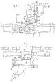
- Agricultural tractor With a lateral distance to the median longitudinal plane Agricultural tractor is in two in the vehicle longitudinal direction swivel bearings 1, 2 supported one behind the other on the chassis a wishbone arrangement 3 pivotally mounted.
- An in Vehicle longitudinal direction forward stub 3a of the Handlebar assembly 3 forms together with one mounted thereon Rigid axis 4, of which only a middle part and a part of the steering linkage is shown, a self-aligning bearing 5, around which the Rigid axis 4 is pendulum corresponding to the angle a.
- both articulation points of the Hydraulic cylinder 6 in the neutral position shown Rigid axis 4 are at least approximately the same height.
- the Hydraulic cylinder 6 for the rebounding and rebounding Handlebar assembly 3 is not an obstacle, since it is about his chassis-side pivot point swiveled.
- a displaceable in the hydraulic cylinder 6 with the piston rod 6a connected piston divides the cylinder interior into known way in two pressure rooms, in the pressure medium lines 10, 11 lead into.
- Both pressure medium lines go from an assigned, in a locked position or a Open position switchable directional valve 12, 13 from that on a pressure medium line 15 and a starting from a pump 14 one leading to a pressure medium container 16 Pressure fluid line 17 is connected.
- the directional control valves 12, 13 can be controlled electrically by means of a control device 18, which the requirements of the vehicle driver with regard to desired pendulum type of the rigid axis 4 in corresponding signals the directional control valves 12, 13 implements.
- Valve 12 Valve 13 Possibility of movement a a Swinging of the rigid axle blocked in a set pendulum position b b free commuting b a Swiveling the rigid axis counterclockwise into a desired pendulum position a b Swiveling the rigid axis clockwise into a desired pendulum position
- a Hydraulic cylinder 6 associated position sensor 19 for the relative Position of the piston in or the relative position of the piston rod 6a connected to the hydraulic cylinder 6. This allows Required in the switch position b / b of the directional control valves 12, 13 in Free swing achievable swing angle of the rigid axis 4 Pendulum angle smaller than the max. Pendulum angle ⁇ can be set.
- FIG. 3 differs from that 1 in that instead of a double-acting Hydraulic cylinder two single-acting hydraulic cylinders 20, 21 are used.
- Each of these hydraulic cylinders is one of the directional control valves 12, 13 assigned, depending on the Switch position of the directional valve in question is its only pressure chamber either with the pump 14 or the pressure medium container 16 connected is.
- switchable directional valves can increase the pendulum capacity of the Rigid axis 4 can be influenced in the desired manner.
Landscapes
- Engineering & Computer Science (AREA)
- Mechanical Engineering (AREA)
- Vehicle Body Suspensions (AREA)
- Arrangement Or Mounting Of Propulsion Units For Vehicles (AREA)
Claims (4)
- Installation pour limiter le mouvement pendulaire d'un essieu rigide (4) d'un véhicule utilitaire, notamment d'un tracteur agricole, accrochée par l'intermédiaire d'un palier pendulaire (5) à un dispositif de bras (3) suspendu par rapport au châssis (9) du véhicule,
les mouvements pendulaires de l'essieu rigide (3) étant limités par des éléments de butée agissant sur ceux-ci et coopérant avec des appuis de pression du côté du châssis,
caractérisée en ce qu'
au dessus du palier pendulaire (5), en un point d'articulation de l'essieu rigide (4), est articulé au moins un vérin hydraulique (6) commandé, sollicité en pression et dirigé dans la direction transversale du véhicule, ce vérin s'appuyant, lorsque le dispositif de bras (3) n'est pas en compression, du côté du châssis du véhicule, au moins sensiblement à la même hauteur que le point d'articulation (7) sur le point d'articulation (8) de l'essieu rigide (4). - Installation selon la revendication 1,
caractérisée par
deux vérins hydrauliques (20, 21) à simple effet, opposés, agissant sur le point d'articulation de l'essieu rigide (4). - Installation selon l'une quelconque des revendications 1 ou 2,
caractérisée par
une installation de commande (18) pour appliquer la pression aux vérins hydrauliques (6, 20, 21), qui est reliée pour la transmission des signaux à une installation fournissant un signal correspondant à la position pendulaire de l'essieu rigide (4) et, lorsqu'on atteint une position pendulaire prédéterminée pour l'essieu rigide (4), cela produit un blocage hydraulique du ou des vérins hydrauliques (6, 20, 21). - Installation selon la revendication 3,
caractérisée en ce que
le ou les vérins hydrauliques (6, 20) sont équipés d'un capteur de position (18) pour déterminer la position de la tige de piston (6a).
Applications Claiming Priority (2)
| Application Number | Priority Date | Filing Date | Title |
|---|---|---|---|
| DE19616302A DE19616302A1 (de) | 1996-04-24 | 1996-04-24 | Einrichtung zum Begrenzen der Pendelbewegung einer Starrachse eines Nutzfahrzeuges, insbesondere eines Ackerschleppers |
| DE19616302 | 1996-04-24 |
Publications (3)
| Publication Number | Publication Date |
|---|---|
| EP0803384A2 EP0803384A2 (fr) | 1997-10-29 |
| EP0803384A3 EP0803384A3 (fr) | 1999-04-21 |
| EP0803384B1 true EP0803384B1 (fr) | 2000-11-22 |
Family
ID=7792265
Family Applications (1)
| Application Number | Title | Priority Date | Filing Date |
|---|---|---|---|
| EP97105504A Expired - Lifetime EP0803384B1 (fr) | 1996-04-24 | 1997-04-03 | Dispositif pour limiter le mouvement pendulaire d'un essieu rigide d'un véhicule utilitaire, notamment d'un tracteur agricole |
Country Status (3)
| Country | Link |
|---|---|
| EP (1) | EP0803384B1 (fr) |
| AT (1) | ATE197694T1 (fr) |
| DE (2) | DE19616302A1 (fr) |
Cited By (1)
| Publication number | Priority date | Publication date | Assignee | Title |
|---|---|---|---|---|
| KR100952534B1 (ko) * | 2005-09-29 | 2010-04-12 | 가부시끼 가이샤 구보다 | 휠식 작업기 |
Families Citing this family (6)
| Publication number | Priority date | Publication date | Assignee | Title |
|---|---|---|---|---|
| GB2336573B (en) * | 1998-04-21 | 2002-02-13 | Agco Gmbh & Co | Utility vehicle with rigid axle |
| IT1302736B1 (it) * | 1998-10-15 | 2000-09-29 | Carraro Spa | Sistema di sospensione ad assale oscillante, in particolare pertrattrici. |
| IT1304143B1 (it) * | 1998-12-02 | 2001-03-07 | New Holland Italia Spa | Gruppo assale anteriore di un trattore, o di un autoveicolo similare. |
| EP1234695A1 (fr) * | 2001-02-23 | 2002-08-28 | Dana Italia S.p.A | Essieu suspendu amorti, en particulier pour machines agricoles, véhicules industriels ou analogue |
| BE1018654A3 (nl) * | 2009-02-12 | 2011-06-07 | Didden Luc | Kniklader. |
| DK2218835T3 (da) * | 2009-02-12 | 2013-02-11 | Toine Brock Constructie Mechanisatie B V | Skovllæsser indbefattende to hængslede rammer |
Family Cites Families (8)
| Publication number | Priority date | Publication date | Assignee | Title |
|---|---|---|---|---|
| US4053171A (en) * | 1976-04-29 | 1977-10-11 | Westinghouse Air Brake Company | Spring suspension arrangement for off-road vehicles |
| US4393959A (en) * | 1980-12-10 | 1983-07-19 | Allis-Chalmers Corporation | Hydraulic stabilizer for axle on mast lift vehicle |
| DE3901757A1 (de) * | 1988-01-29 | 1989-08-10 | Zahnradfabrik Friedrichshafen | Aufhaengung einer starrachse eines schleppers |
| DE9017845U1 (de) * | 1990-08-08 | 1992-03-26 | MAN Nutzfahrzeuge AG, 8000 München | Starrachse mit hydropneumatischen Federbeinen in Nutzfahrzeugen |
| US5082085A (en) * | 1990-08-30 | 1992-01-21 | Up-Right, Inc. | Platform leveling apparatus |
| DE4129715A1 (de) * | 1991-09-06 | 1993-03-11 | Kloeckner Humboldt Deutz Ag | Anlenkung einer abgefederten, gelenkten achse fuer gelaendegaengige fahrzeuge |
| DE4235264B4 (de) * | 1992-10-20 | 2004-07-08 | Same Deutz-Fahr S.P.A., Treviglio | Hydraulische Vorderachssicherung und Blockierung für ein landwirtschaftliches Fahrzeug |
| FR2702012B1 (fr) * | 1993-02-25 | 1995-05-24 | Sacmi | Dispositif hydraulique de contrôle des oscillations d'un corps mobile et application au train oscillant d'un véhicule moteur. |
-
1996
- 1996-04-24 DE DE19616302A patent/DE19616302A1/de not_active Withdrawn
-
1997
- 1997-04-03 AT AT97105504T patent/ATE197694T1/de not_active IP Right Cessation
- 1997-04-03 EP EP97105504A patent/EP0803384B1/fr not_active Expired - Lifetime
- 1997-04-03 DE DE59702651T patent/DE59702651D1/de not_active Expired - Fee Related
Cited By (1)
| Publication number | Priority date | Publication date | Assignee | Title |
|---|---|---|---|---|
| KR100952534B1 (ko) * | 2005-09-29 | 2010-04-12 | 가부시끼 가이샤 구보다 | 휠식 작업기 |
Also Published As
| Publication number | Publication date |
|---|---|
| EP0803384A3 (fr) | 1999-04-21 |
| EP0803384A2 (fr) | 1997-10-29 |
| DE19616302A1 (de) | 1997-10-30 |
| DE59702651D1 (de) | 2000-12-28 |
| ATE197694T1 (de) | 2000-12-15 |
Similar Documents
| Publication | Publication Date | Title |
|---|---|---|
| EP0932512B1 (fr) | Suspension oscillante d'essieu | |
| DE3826930C2 (de) | Radaufhängungssystem | |
| EP0390787B1 (fr) | Tracteur utile en agriculture et en genie civil a essieu rigide dirigeable | |
| EP0512550B1 (fr) | Suspension d'essieu directeur à ressort | |
| DE10133424A1 (de) | Hinterachse eines Personenkraftwagens mit fünf einzelnen Lenkern | |
| DE2256934A1 (de) | Fahrzeugaufhaengung, insbesondere fuer ein motorfahrzeug | |
| DE3514823A1 (de) | Unabhaengige radaufhaengung fuer kraftfahrzeuge | |
| EP1302342A2 (fr) | Système de suspension d'un essieu oscillant | |
| EP0803384B1 (fr) | Dispositif pour limiter le mouvement pendulaire d'un essieu rigide d'un véhicule utilitaire, notamment d'un tracteur agricole | |
| DE19918146A1 (de) | Fahrzeug mit einer Starrachse | |
| DE4235264B4 (de) | Hydraulische Vorderachssicherung und Blockierung für ein landwirtschaftliches Fahrzeug | |
| DE10210556A1 (de) | Fahrzeugachse | |
| EP0647554A2 (fr) | Direction désactivable pour essieux | |
| DE3511336A1 (de) | Auf raedern fahrbare baumaschine mit knicklenkung, wie schaufellader, planierfahrzeug o.dgl. | |
| DE2723672A1 (de) | Fahrzeugradaufhaengungssystem | |
| DE102007025598A1 (de) | Fahrzeug mit pendelbeweglicher Achse | |
| DE60116179T2 (de) | Maschine zur Beförderung von Lasten | |
| DE4038772C2 (de) | Nutzfahrzeug mit einer schwenkbaren Fahrerkabine | |
| DE69809847T2 (de) | Steuerungseinrichtung und hydraulischer Zylinder für eine schwenkbare Nutzfahrzeugachse | |
| EP0754576B1 (fr) | Suspension d'un essieu directeur d'un véhicule tout-terrain | |
| EP0259801B1 (fr) | Dispositif d'attelage pour tracteur agricole | |
| CH675102A5 (fr) | ||
| DE202005011305U1 (de) | Vorrichtung zur Seitenstabilisierung der Unterlenker einer Geräteanbauvorrichtung eines Ackerschleppers | |
| DE69817509T2 (de) | Gefederte Streuvorrichtung | |
| DE3532006C2 (fr) |
Legal Events
| Date | Code | Title | Description |
|---|---|---|---|
| PUAI | Public reference made under article 153(3) epc to a published international application that has entered the european phase |
Free format text: ORIGINAL CODE: 0009012 |
|
| AK | Designated contracting states |
Kind code of ref document: A2 Designated state(s): AT DE FR GB IT |
|
| RAP1 | Party data changed (applicant data changed or rights of an application transferred) |
Owner name: AGCO GMBH & CO |
|
| RAP1 | Party data changed (applicant data changed or rights of an application transferred) |
Owner name: AGCO GMBH & CO |
|
| RAP1 | Party data changed (applicant data changed or rights of an application transferred) |
Owner name: AGCO GMBH & CO. |
|
| PUAL | Search report despatched |
Free format text: ORIGINAL CODE: 0009013 |
|
| AK | Designated contracting states |
Kind code of ref document: A3 Designated state(s): AT DE FR GB IT |
|
| 17P | Request for examination filed |
Effective date: 19991006 |
|
| GRAG | Despatch of communication of intention to grant |
Free format text: ORIGINAL CODE: EPIDOS AGRA |
|
| GRAG | Despatch of communication of intention to grant |
Free format text: ORIGINAL CODE: EPIDOS AGRA |
|
| GRAH | Despatch of communication of intention to grant a patent |
Free format text: ORIGINAL CODE: EPIDOS IGRA |
|
| 17Q | First examination report despatched |
Effective date: 20000518 |
|
| GRAH | Despatch of communication of intention to grant a patent |
Free format text: ORIGINAL CODE: EPIDOS IGRA |
|
| GRAA | (expected) grant |
Free format text: ORIGINAL CODE: 0009210 |
|
| AK | Designated contracting states |
Kind code of ref document: B1 Designated state(s): AT DE FR GB IT |
|
| REF | Corresponds to: |
Ref document number: 197694 Country of ref document: AT Date of ref document: 20001215 Kind code of ref document: T |
|
| REF | Corresponds to: |
Ref document number: 59702651 Country of ref document: DE Date of ref document: 20001228 |
|
| ET | Fr: translation filed | ||
| ITF | It: translation for a ep patent filed | ||
| GBT | Gb: translation of ep patent filed (gb section 77(6)(a)/1977) |
Effective date: 20010222 |
|
| PLBE | No opposition filed within time limit |
Free format text: ORIGINAL CODE: 0009261 |
|
| STAA | Information on the status of an ep patent application or granted ep patent |
Free format text: STATUS: NO OPPOSITION FILED WITHIN TIME LIMIT |
|
| 26N | No opposition filed | ||
| REG | Reference to a national code |
Ref country code: GB Ref legal event code: IF02 |
|
| PGFP | Annual fee paid to national office [announced via postgrant information from national office to epo] |
Ref country code: AT Payment date: 20060309 Year of fee payment: 10 |
|
| PG25 | Lapsed in a contracting state [announced via postgrant information from national office to epo] |
Ref country code: AT Free format text: LAPSE BECAUSE OF NON-PAYMENT OF DUE FEES Effective date: 20070403 |
|
| PGFP | Annual fee paid to national office [announced via postgrant information from national office to epo] |
Ref country code: IT Payment date: 20090429 Year of fee payment: 13 Ref country code: FR Payment date: 20090414 Year of fee payment: 13 Ref country code: DE Payment date: 20090422 Year of fee payment: 13 |
|
| PGFP | Annual fee paid to national office [announced via postgrant information from national office to epo] |
Ref country code: GB Payment date: 20090421 Year of fee payment: 13 |
|
| GBPC | Gb: european patent ceased through non-payment of renewal fee |
Effective date: 20100403 |
|
| REG | Reference to a national code |
Ref country code: FR Ref legal event code: ST Effective date: 20101230 |
|
| PG25 | Lapsed in a contracting state [announced via postgrant information from national office to epo] |
Ref country code: DE Free format text: LAPSE BECAUSE OF NON-PAYMENT OF DUE FEES Effective date: 20101103 |
|
| PG25 | Lapsed in a contracting state [announced via postgrant information from national office to epo] |
Ref country code: IT Free format text: LAPSE BECAUSE OF NON-PAYMENT OF DUE FEES Effective date: 20100403 Ref country code: GB Free format text: LAPSE BECAUSE OF NON-PAYMENT OF DUE FEES Effective date: 20100403 |
|
| PG25 | Lapsed in a contracting state [announced via postgrant information from national office to epo] |
Ref country code: FR Free format text: LAPSE BECAUSE OF NON-PAYMENT OF DUE FEES Effective date: 20100430 |