EP0803411B1 - Coussin gonflable, en particulier pour un module de sac gonflable latéral - Google Patents
Coussin gonflable, en particulier pour un module de sac gonflable latéral Download PDFInfo
- Publication number
- EP0803411B1 EP0803411B1 EP97250024A EP97250024A EP0803411B1 EP 0803411 B1 EP0803411 B1 EP 0803411B1 EP 97250024 A EP97250024 A EP 97250024A EP 97250024 A EP97250024 A EP 97250024A EP 0803411 B1 EP0803411 B1 EP 0803411B1
- Authority
- EP
- European Patent Office
- Prior art keywords
- air bag
- limiting strap
- tether
- chambers
- limiting
- Prior art date
- Legal status (The legal status is an assumption and is not a legal conclusion. Google has not performed a legal analysis and makes no representation as to the accuracy of the status listed.)
- Expired - Lifetime
Links
- 241000826860 Trapezium Species 0.000 claims 3
- 241001660693 Trapezia Species 0.000 claims 1
- 238000005192 partition Methods 0.000 description 4
- 230000003111 delayed effect Effects 0.000 description 2
- 238000009958 sewing Methods 0.000 description 2
- 238000004026 adhesive bonding Methods 0.000 description 1
- 238000007664 blowing Methods 0.000 description 1
- 230000003116 impacting effect Effects 0.000 description 1
- 238000002347 injection Methods 0.000 description 1
- 239000007924 injection Substances 0.000 description 1
- 238000000926 separation method Methods 0.000 description 1
Images


Classifications
-
- B—PERFORMING OPERATIONS; TRANSPORTING
- B60—VEHICLES IN GENERAL
- B60R—VEHICLES, VEHICLE FITTINGS, OR VEHICLE PARTS, NOT OTHERWISE PROVIDED FOR
- B60R21/00—Arrangements or fittings on vehicles for protecting or preventing injuries to occupants or pedestrians in case of accidents or other traffic risks
- B60R21/02—Occupant safety arrangements or fittings, e.g. crash pads
- B60R21/16—Inflatable occupant restraints or confinements designed to inflate upon impact or impending impact, e.g. air bags
- B60R21/23—Inflatable members
- B60R21/231—Inflatable members characterised by their shape, construction or spatial configuration
- B60R21/233—Inflatable members characterised by their shape, construction or spatial configuration comprising a plurality of individual compartments; comprising two or more bag-like members, one within the other
-
- B—PERFORMING OPERATIONS; TRANSPORTING
- B60—VEHICLES IN GENERAL
- B60R—VEHICLES, VEHICLE FITTINGS, OR VEHICLE PARTS, NOT OTHERWISE PROVIDED FOR
- B60R21/00—Arrangements or fittings on vehicles for protecting or preventing injuries to occupants or pedestrians in case of accidents or other traffic risks
- B60R21/02—Occupant safety arrangements or fittings, e.g. crash pads
- B60R21/16—Inflatable occupant restraints or confinements designed to inflate upon impact or impending impact, e.g. air bags
- B60R21/23—Inflatable members
- B60R21/231—Inflatable members characterised by their shape, construction or spatial configuration
- B60R21/23138—Inflatable members characterised by their shape, construction or spatial configuration specially adapted for side protection
-
- B—PERFORMING OPERATIONS; TRANSPORTING
- B60—VEHICLES IN GENERAL
- B60R—VEHICLES, VEHICLE FITTINGS, OR VEHICLE PARTS, NOT OTHERWISE PROVIDED FOR
- B60R21/00—Arrangements or fittings on vehicles for protecting or preventing injuries to occupants or pedestrians in case of accidents or other traffic risks
- B60R21/02—Occupant safety arrangements or fittings, e.g. crash pads
- B60R21/16—Inflatable occupant restraints or confinements designed to inflate upon impact or impending impact, e.g. air bags
- B60R21/23—Inflatable members
- B60R21/231—Inflatable members characterised by their shape, construction or spatial configuration
- B60R21/2334—Expansion control features
- B60R21/2338—Tethers
-
- B—PERFORMING OPERATIONS; TRANSPORTING
- B60—VEHICLES IN GENERAL
- B60R—VEHICLES, VEHICLE FITTINGS, OR VEHICLE PARTS, NOT OTHERWISE PROVIDED FOR
- B60R21/00—Arrangements or fittings on vehicles for protecting or preventing injuries to occupants or pedestrians in case of accidents or other traffic risks
- B60R21/02—Occupant safety arrangements or fittings, e.g. crash pads
- B60R21/16—Inflatable occupant restraints or confinements designed to inflate upon impact or impending impact, e.g. air bags
- B60R21/23—Inflatable members
- B60R21/231—Inflatable members characterised by their shape, construction or spatial configuration
- B60R21/233—Inflatable members characterised by their shape, construction or spatial configuration comprising a plurality of individual compartments; comprising two or more bag-like members, one within the other
- B60R2021/23324—Inner walls crating separate compartments, e.g. communicating with vents
-
- B—PERFORMING OPERATIONS; TRANSPORTING
- B60—VEHICLES IN GENERAL
- B60R—VEHICLES, VEHICLE FITTINGS, OR VEHICLE PARTS, NOT OTHERWISE PROVIDED FOR
- B60R21/00—Arrangements or fittings on vehicles for protecting or preventing injuries to occupants or pedestrians in case of accidents or other traffic risks
- B60R21/02—Occupant safety arrangements or fittings, e.g. crash pads
- B60R21/16—Inflatable occupant restraints or confinements designed to inflate upon impact or impending impact, e.g. air bags
- B60R21/23—Inflatable members
- B60R21/231—Inflatable members characterised by their shape, construction or spatial configuration
- B60R21/2334—Expansion control features
- B60R21/2338—Tethers
- B60R2021/23382—Internal tether means
Definitions
- the invention relates to an airbag, in particular for a Side airbag module, according to the preamble of claim 1.
- a side impact protection device is known from DE 44 30 412 C1 for an occupant of a vehicle with a an inflatable gas cushion interacting with a filling device known. Inside the gas cushion are at this Device tether provided the gas cushion at least divide into two chambers, i.e. between two chambers there are several adjacent tether straps. Between two adjacent tethers are either open gaps provided or the tethers are through Tear seams joined together. These tear when filled of the gas bag so that between the adjacent tethers a gap also arises.
- This type of arrangement of a tether has the disadvantage on that the size and shape of the chambers is limited Scope by changing the angle of inclination of the tether sections between the top and bottom of the airbag are changeable.
- a gas bag is also known from DE 44 43 027 A1, through a flexible partition inside the gas bag is divided into two chambers.
- the partition extends over the entire length or width and depth of the Gas bag and it has an opening for connecting the in both chambers.
- the partition runs in the inflated Straightforward condition.
- FR 2 227 979 A1 describes an airbag for a side airbag module according to the preamble of claim 1, which is a plurality longitudinally from each other spaced, vertically extending tether, that divide the gas bag into different chambers, the longer side edges attached to the gas bag the tether in the inflated state of the gas bag some have a curved course and the narrow The ends of the tether are at a distance from the gas bag.
- JP 7-329667 A an airbag is shown, the one A plurality of tether straps running in different directions has that divide the gas bag into different areas.
- a gas bag for a side airbag module is known from US Pat. No. 5,586,782 known that one slightly inclined to the vertical running tether that the gas bag in two Chambers divided, with those on opposite surfaces of the gas bag attached side edges of the tether in inflated state of the gas bag is trapezoidal and a narrow end of the tether at a distance from the gas bag is arranged.
- the two chambers of the gas bag face different volumes so that after inflating of the gas bag with different internal pressures for an impacting occupant be kept ready.
- the invention has for its object a gas bag to further improve the type mentioned at the beginning.
- an airbag with the characteristics of the generic term of claim 1 further provided that at least one for dividing the gas bag into different ones Chambers provided tether when arranging the gas bag in a motor vehicle door in the vehicle longitudinal direction runs and that both attached to the gas bag Side edges run in different directions in such a way that the expansion of the inflated gas bag varies across the plane of the door between the ends of the tether and thereby along the vehicle longitudinal direction to the for the gas bag next to a vehicle seat standing space is customizable.
- the gas bag is easily different in different chambers Subdivide size and shape and continue to do so the shape of the inflated gas bag can be influenced.
- no openings in the tether or not several tethers must be present between those when inflating of the gas bag column are present, although a delayed but still allow quick filling of the second chamber. Rather, a satisfactory filling is the second chamber even when arranging only one tether as Chamber wall possible, only on the narrow end edges can flow around.
- a tether can be between two Fasten chambers in the gas bag more easily than several tether straps, that have to be aligned with each other.
- the running in the longitudinal direction of the vehicle Tether is formed such that the extension of the inflated airbag (width of the airbag) across Door level varies along the vehicle's longitudinal direction, can the width of the gas bag to the constructive Environment to be adjusted next to a vehicle seat.
- the tether on its narrow Ends arched for increased stability the ends and to influence the shape of the chamber. Furthermore, the longer side edges of the The tether must be continuously attached to the gas bag.
- the tether divides the gas bag in two chambers, the first of which is connected to the filling device is and the tether runs on its narrow Ends arcuate towards the second chamber.
- Influencing the shape and size of neighboring chambers is also possible in that the attached to the gas bag longer side edges of the tether overall curved run.
- tethers are arranged, they can be divided one tether or several tether is provided his.
- the use of multiple tethers for subdivision different chambers is not comparable to the arrangement of several tethers between two chambers in the known gas bag mentioned above. Rather is also in this case only between two neighboring chambers a tether is provided.
- the longer attached to the gas bag Side edges of the tether are V-shaped.
- three chambers are formed in the gas bag be inflated one after the other.
- a further subdivision the airbag is shaped by a zigzag Course of the longer side edges attached to the gas bag of the tether possible.
- the shape of the inflated gas bag is influenced also in that the side edges of the tether run in different directions. While with one parallel course of the side edges also the adjacent ones Sides of the airbag run parallel after it has been unfolded, this is not always the case, especially with side airbags expedient. There the gas bag is particularly constructive Adapt to the environment, e.g. to the space between the seat and the B-pillar.
- the tether is trapezoidal. This ensures that the gas bag in the unfolded state has a different thickness, which is continuous between the ends of the tether changed and adaptable to the available space.
- the tether has the shape of a double trapezoid having both trapezoids one of the parallel sides have as a common side.
- this embodiment takes the thickness of the deployed airbag from the common Side out to the ends of the tether continuously or down, depending on whether the double trapezoid is wider in the middle or narrower than at the ends.
- the Tether has sections of different shape and / or the tether in the area of different chambers different Have shapes. This makes it possible to Airbag inflated even better to the most varied Adapt spatial conditions.
- the gas bag is made from a plate-shaped lower and upper part, between which the tether extends or the tether extend and to which they are attached.
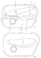
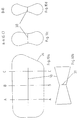
- the gas bag according to Figures 1 to 3 consists of a Lower part 1 and an upper part 2, which are seamed at the edge 3 are interconnected.
- the bottom part is with one Injection mouth 4 provided on a not shown Gas generator is connected.
- Between the bottom and the upper part extends across the airbag Tether 5a, 5b or 5c.
- the tether is straight and has arcuate ends 6, 7.
- the tether is on its long sides 8, 9 by seams 8a, 9a with the lower part or upper part connected. Sewing the continuous
- the tether is easier than sewing several side by side single tether between two neighboring ones Chambers. Other types of attachment, such as Gluing is easier to implement.
- the tether divides the gas bag into two chambers 10, 11 which are connected to each other at both ends of the tether, since the tether is not up to the edge of the gas bag extends. This subdivision ensures that the Airbag in the area of the chamber 10 with the blowing mouth 4 is inflated first, and that it is in the area of the chamber 11 is inflated with a delay.
- Inflation of the gas bag can be due to the size ratio the chambers are influenced to each other.
- This size ratio can by a different in Fig. 1 shown Location of the tether can be influenced.
- the different angular position of the tether shown 5a, 5b and 5c is not only the size ratio of the Chambers changed, but every single chamber is too changed in shape. So is the chamber 10 when arranged of the tether 5a larger in its right area than in left area while these areas with a tether 5b are the same size. In contrast, with a tether 5c left area of chamber 10 larger than the right area.
- the shape of the chamber 11 changes accordingly in the opposite Sense, i.e., enlarged areas of the chamber 10 face smaller areas of the chamber 11.
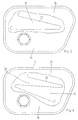
- FIG. 4 Another way to influence the size ratio the chambers is shown in FIG. 4.
- a tether 12 is provided that is curved. It can thereby be achieved that the middle area of the Chambers has a different size than the side Areas near the ends of the tether.
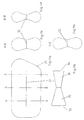
- FIG. 5 While in the embodiments shown so far Airbag divided into two chambers by the tether 5, an embodiment is shown in FIG. in which the tether divides the gas bag into three chambers. For this purpose there is a V-shaped tether 13 provided that the gas bag in three chambers 14, 15, 16th divided. Due to the three-part division of the airbag, there is one finer gradation of delayed inflation of certain areas to achieve the gas bag.
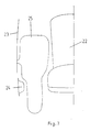
- FIG. 7 is an example of a gas bag for one Driver's seat recognizable how the gas bag adapts to the constructive Environment must adapt. From the figure are a driver's seat 22, a door 23 and the B-pillar 24 of a motor vehicle recognizable. There is also an inflated gas bag 25 recognizable, which extends out of the door. Out the figure shows that the gas bag in the door area has a greater width than between the B-pillar and the seat. These and other forms of the airbag are included the tether straps provided as partitions of the following Embodiments achievable.
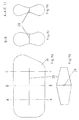
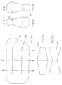
- FIGS. 8a to d there is an airbag 26 shown, in which a tether 27 is provided.
- This has a trapezoidal shape, i.e. the side edges 27a and 27b run in different directions, such as it can be seen from Fig. 8b. In this form it will Tail strap cut.
- the tether shows the gas bag in the unfolded state at the interface A is wider than at the interface B, as can be seen from FIGS. 8c and 8d.
- FIGS. 9a to d there is an airbag 26 provided with a tether 28 which is in the form of a Has double trapezoids.
- the two trapezoids point as common side the larger side 29 of the parallel sides on. This traps the tether from the center its ends too narrow. Therefore, the gas bag in the unfolded state at interface B a larger one Spread as wide as at interfaces A and C as it is Figures 9c and 9d can be seen.
- Figures 10a to 10d show an embodiment, at which the tether 30 also has the shape of a double trapezoid having.
- the difference to the embodiment of Figures 9a to 9d is that the smaller side 31 of the parallel sides are provided as a common side is. This traps the tether from the center its ends too wide.
- the airbag therefore shows in the unfolded State at interface B a lower one Spread as wide as at positions A and C as shown in the Figures 10c and 10d emerges.
- FIGS. 11a to 11e The further embodiment of the embodiment according to the FIGS. 10a to 10d provide in FIGS. 11a to 11e, that a double trapezoidal tether 32 different has wide ends 33, 34 so that the tether is different has shaped portions 35, 36. This will achieved that the gas bag in the unfolded state to the Interfaces A and C have different widths, as can be seen from FIGS. 11c and 11e.
- FIGS. 12a to 12e shown with two tethers 37, 38, the have different shapes. This corresponds to Tether 37 the tether 28 of FIG. 9b and the tether 38 the tether 30 of FIG. 10b. As from Figures 12d and 12e can be seen, the deployed gas bag a different one in the middle as well as at the ends Course on.
- the illustrated embodiments show the example Possibilities for influencing the gas bag geometry through the tether according to the invention. It can be seen that any other forms of tether are possible.
Landscapes
- Engineering & Computer Science (AREA)
- Mechanical Engineering (AREA)
- Air Bags (AREA)
Claims (12)
- Sac à gaz pour un module d'airbag latéral d'un véhicule automobile, qui peut être gonflé à l'aide d'un dispositif de remplissage et est constitué par au moins deux chambres reliées entre elles, et dans lequelcaractérisé en cea) entre deux chambres respectives il est prévu, en tant que paroi, une bande de séparation (27, 28, 30, 32), qui est fixée par respectivement l'un des grands bords latéraux (27a, 27b) à des surfaces opposées du sac à gaz (25, 26)b) lorsque le sac à gaz (25, 26) est à l'état gonflé, les bords latéraux (27a, 27b) de la bande de séparation (27, 28, 30, 32) présentent au moins en partie un tracé qui diffère d'une droite et/ou s'étendent dans des directions différentes, etc) les extrémités étroites (33, 34) de la bande de séparation (27, 28, 30, 32) s'étendent à une certaine distance du sac à gaz (25, 26),
que dans le cas où le sac à gaz (25, 26) est disposé dans une portière (23) du véhicule, la bande de séparation (27, 28, 30, 32) s'étend dans la direction longitudinale du véhicule et que ses deux bords latéraux (27a, 27b) fixés au sac à gaz s'étendent dans des directions différentes de telle sorte que la dilatation du sac à gaz gonflé (25, 26) transversalement par rapport au plan de la portière entre les extrémités de la bande de séparation (27, 28, 30, 32) est modifiée et de ce fait est adaptée, dans la direction longitudinale du véhicule, à l'espace qui est disponible pour le sac à gaz (25, 26) à côté d'un siège (22) du véhicule. - Sac à gaz selon la revendication 1, caractérisé en ce que la bande de séparation s'étend avec une forme arquée au niveau de ses extrémités étroites (6, 7).
- Sac à gaz selon la revendication 1 ou 2,
caractérisé en ce que les grands bords latéraux (8, 9) de la bande de séparation sont fixés d'une manière continue au sac à gaz. - Sac à gaz selon au moins l'une des revendications précédentes, caractérisé en ce que la bande de séparation divise le sac à gaz en deux chambres (10, 11) , dont la première (10) est raccordée au dispositif de remplissage, et que la bande de séparation (5a, 5b, 5c) s'étend avec une forme arquée au niveau de ses extrémités étroites (6, 7) en direction de la seconde chambre (11).
- Sac à gaz selon au moins l'une des revendications précédentes, caractérisé en ce que les grands bords latéraux, qui sont fixés au sac à gaz, de la bande de séparation (12) ont globalement une forme incurvée.
- Sac à gaz selon au moins l'une des revendications précédentes, caractérisé en ce que dans le cas de la disposition de plus de deux chambres, il est prévu, pour réaliser la subdivision entre ces chambres, une bande de séparation (16, 17) ou plusieurs bandes de séparation (37, 38).
- Sac à gaz selon au moins l'une des revendications précédentes, caractérisé en ce que les grands côtés latéraux, fixés au sac à gaz, de la bande de séparation (13) sont agencés en forme de V et le sac à gaz est subdivisé par la bande de séparation en trois chambres (14, 15, 16).
- Sac à gaz selon au moins l'une des revendications précédentes, caractérisé en ce que les grands bords latéraux, fixés au sac à gaz, de la bande de séparation (17) s'étendent en zigzag.
- Sac à gaz selon au moins l'une des revendications précédentes, caractérisé en ce que la bande de séparation (27) possède une forme trapézoïdale et que les côtés non parallèles (27a, 27b) du trapèze sont reliés au sac à gaz.
- Sac à gaz selon au moins l'une des revendications précédentes, caractérisé en ce que la bande de séparation (28, 30, 32) possède la forme d'un trapèze double, les deux trapèzes possédant l'un des côtés parallèles en tant que côté commun (29, 31) et que les côtés non parallèles du trapèze sont reliés au sac à gaz.
- Sac à gaz selon au moins l'une des revendications précédentes, caractérisé en ce que le sac à gaz est constitué respectivement par une partie inférieure (1) et une partie supérieure (2) en forme de plaques, entre lesquelles la bande de séparation (5a, 5b, 5, 1, 13, 17) s'étend et auxquelles elle est fixée.
- Sac à gaz selon au moins l'une des revendications précédentes, caractérisé en ce que la bande de séparation (32) comporte des parties (35, 36) ayant des formes différentes et/ou que les bandes de séparation (37, 38) possèdent des formes différentes au niveau de chambres différentes.
Priority Applications (3)
| Application Number | Priority Date | Filing Date | Title |
|---|---|---|---|
| JP9088505A JP3016746B2 (ja) | 1996-04-24 | 1997-04-07 | ガスバッグ |
| US08/847,384 US6032977A (en) | 1996-04-24 | 1997-04-23 | Gas bag |
| BR9701910A BR9701910A (pt) | 1996-04-24 | 1997-04-23 | Saco de gás especialmente para um módulo de airbag lateral |
Applications Claiming Priority (2)
| Application Number | Priority Date | Filing Date | Title |
|---|---|---|---|
| DE29608055U DE29608055U1 (de) | 1996-04-24 | 1996-04-24 | Gassack, insbesondere für ein Seitenairbagmodul |
| DE29608055U | 1996-04-24 |
Publications (2)
| Publication Number | Publication Date |
|---|---|
| EP0803411A1 EP0803411A1 (fr) | 1997-10-29 |
| EP0803411B1 true EP0803411B1 (fr) | 2001-05-16 |
Family
ID=8023505
Family Applications (1)
| Application Number | Title | Priority Date | Filing Date |
|---|---|---|---|
| EP97250024A Expired - Lifetime EP0803411B1 (fr) | 1996-04-24 | 1997-02-04 | Coussin gonflable, en particulier pour un module de sac gonflable latéral |
Country Status (2)
| Country | Link |
|---|---|
| EP (1) | EP0803411B1 (fr) |
| DE (2) | DE29608055U1 (fr) |
Cited By (1)
| Publication number | Priority date | Publication date | Assignee | Title |
|---|---|---|---|---|
| DE102004031865A1 (de) * | 2004-07-01 | 2006-02-09 | Autoliv Development Ab | Seitenairbagmodul für einen Fahrzeugsitz eines Kraftfahrzeuges |
Families Citing this family (7)
| Publication number | Priority date | Publication date | Assignee | Title |
|---|---|---|---|---|
| DE19652019A1 (de) * | 1996-12-13 | 1998-06-18 | Takata Europ Gmbh | Luftsack für einen Seitenairbag |
| DE29705133U1 (de) | 1997-03-20 | 1997-07-24 | Trw Repa Gmbh | Gassack für ein Fahrzeuginsassen-Schutzsystem |
| DE19720587A1 (de) * | 1997-05-16 | 1998-11-19 | Porsche Ag | Seitenaufprallschutzeinrichtung für einen Insassen eines Fahrzeuges |
| DE19720584C2 (de) | 1997-05-16 | 2000-11-23 | Porsche Ag | Seitenaufprallschutzeinrichtung für einen Insassen eines Fahrzeuges |
| DE19720585A1 (de) * | 1997-05-16 | 1998-11-19 | Porsche Ag | Seitenaufprallschutzeinrichtung für einen Insassen eines Fahrzeuges |
| DE19720586C2 (de) * | 1997-05-16 | 2000-11-30 | Porsche Ag | Seitenaufprallschutzeinrichtung für einen Insassen eines Fahrzeuges |
| DE29721678U1 (de) | 1997-11-26 | 1998-02-05 | Petri Ag | Vorrichtung zur Beeinflussung der Entfaltung eines Gassacks eines Airbagmoduls |
Family Cites Families (15)
| Publication number | Priority date | Publication date | Assignee | Title |
|---|---|---|---|---|
| US3788665A (en) * | 1971-05-12 | 1974-01-29 | Gen Motors Corp | Occupant restraint system |
| US3897961A (en) * | 1973-05-02 | 1975-08-05 | Chrysler Corp | Inflatable restraint apparatus |
| US4944527A (en) * | 1989-08-31 | 1990-07-31 | Allied-Signal Inc. | Integral retainer, heat shield and assembly |
| JPH03281460A (ja) * | 1990-03-29 | 1991-12-12 | Mazda Motor Corp | 自動車のエアバッグ装置 |
| GB2252083A (en) * | 1991-01-22 | 1992-07-29 | Dowty Woodville Polymer Ltd | Heat resistant vehicle crash bag. |
| JP3168591B2 (ja) * | 1991-03-12 | 2001-05-21 | トヨタ自動車株式会社 | エアバッグ装置 |
| US5160164A (en) * | 1991-06-05 | 1992-11-03 | Trw Vehicle Safety Systems Inc. | Gas deflection device for an air bag assembly |
| JP2731324B2 (ja) * | 1992-06-17 | 1998-03-25 | 株式会社東海理化電機製作所 | エアバッグ装置の袋体及び袋体の製造方法 |
| CA2108394A1 (fr) * | 1992-12-01 | 1994-06-02 | Morton International Inc. | Coussin gonflable a diffuseur d'air en tissu |
| JP3353465B2 (ja) * | 1994-06-13 | 2002-12-03 | タカタ株式会社 | 車両用エアバッグ |
| DE4430412C1 (de) * | 1994-08-26 | 1995-10-12 | Porsche Ag | Seitenaufprallschutzeinrichtung für einen Insassen eines Fahrzeuges |
| DE4443027A1 (de) * | 1994-12-02 | 1996-06-05 | Trw Repa Gmbh | Seitenaufprall-Gassack |
| US5586782A (en) * | 1995-06-26 | 1996-12-24 | Alliedsignal Inc. | Dual pressure side impact air bag |
| DE29517372U1 (de) * | 1995-11-02 | 1996-02-01 | Trw Repa Gmbh | Gassack-Seitenaufprall-Schutzeinrichtung |
| DE29518651U1 (de) * | 1995-11-24 | 1996-02-22 | Trw Repa Gmbh | Doppelkammer-Gassack für ein Fahrzeuginsassen-Rückhaltesystem |
-
1996
- 1996-04-24 DE DE29608055U patent/DE29608055U1/de not_active Expired - Lifetime
-
1997
- 1997-02-04 DE DE59703533T patent/DE59703533D1/de not_active Expired - Lifetime
- 1997-02-04 EP EP97250024A patent/EP0803411B1/fr not_active Expired - Lifetime
Cited By (2)
| Publication number | Priority date | Publication date | Assignee | Title |
|---|---|---|---|---|
| DE102004031865A1 (de) * | 2004-07-01 | 2006-02-09 | Autoliv Development Ab | Seitenairbagmodul für einen Fahrzeugsitz eines Kraftfahrzeuges |
| DE102004031865B4 (de) * | 2004-07-01 | 2009-01-15 | Autoliv Development Ab | Seitenairbagmodul für einen Fahrzeugsitz eines Kraftfahrzeuges |
Also Published As
| Publication number | Publication date |
|---|---|
| DE59703533D1 (de) | 2001-06-21 |
| DE29608055U1 (de) | 1996-07-18 |
| EP0803411A1 (fr) | 1997-10-29 |
Similar Documents
| Publication | Publication Date | Title |
|---|---|---|
| DE60207932T2 (de) | Beinschutzeinrichtung für Fahrzeuginsassen | |
| DE69904985T2 (de) | Airbag für den Kopfschutz von Fahrzeuginsassen | |
| EP0952043B1 (fr) | Dispositif de protection des genoux pour les occupants d'un véhicule | |
| EP0773144B1 (fr) | Sac gonflable pour un système de retenue des passagers d'un véhicule | |
| WO2020156953A1 (fr) | Ensemble sac gonflable destiné à un système de retenue d'un occupant de véhicule automobile | |
| DE102014013649B4 (de) | Adaptives, entfaltbares Rückhalteelement für ein Fahrzeugsicherheitssystem, Gassackmodul und Fahrzeugsicherheitssystem mit einem solchen Rückhalteelement sowie Verwendung des Flossenstrahleffekts in einem adaptiven Rückhaltesystem | |
| DE69803370T2 (de) | Luftsack | |
| EP1391353A2 (fr) | Dispositif pour la protection des occupants | |
| DE4115884A1 (de) | Abdeckung zur aufnahme eines luftsacks | |
| EP0988185A1 (fr) | Module airbag lateral | |
| DE2431302B2 (de) | Energieabsorbierende Stoßstange | |
| EP0803411B1 (fr) | Coussin gonflable, en particulier pour un module de sac gonflable latéral | |
| EP4227168A1 (fr) | Sac gonflable pour un siège de conducteur d'un véhicule, ainsi que module de sac gonflable, système de sécurité d'occupant de véhicule et véhicule doté d'un tel sac à gaz | |
| EP1179456B1 (fr) | Coussin de sécurité et sa méthode de fabrication | |
| EP1477372A1 (fr) | Dispositif de sécurité | |
| EP1062126A1 (fr) | Module d'airbag, notamment module d'airbag pour passager avant | |
| DE19519998C2 (de) | Beifahrerairbagmodul | |
| EP0847902B2 (fr) | Coussin pour airbag latéral | |
| DE10159046B4 (de) | Airbagbefestigung | |
| DE20011327U1 (de) | Schutzkissen für den Kopf eines Fahrzeuginsassen, entsprechende Schutzvorrichtung und entsprechendes Kraftfahrzeug | |
| DE19505160A1 (de) | Fondsitzbank für einen Kombi-Personenkraftwagen | |
| DE102014000317A1 (de) | Airbag-Anordnung | |
| EP1810891B1 (fr) | Module de coussin de sécurité pour véhicules | |
| DE102022114931A1 (de) | Gassack für ein Airbagmodul | |
| DE102005060640B4 (de) | Gassackvorrichtung mit einem aufblasbaren Gassack und einem in dem Gassack angeordneten länglichen Befüllelement |
Legal Events
| Date | Code | Title | Description |
|---|---|---|---|
| PUAI | Public reference made under article 153(3) epc to a published international application that has entered the european phase |
Free format text: ORIGINAL CODE: 0009012 |
|
| AK | Designated contracting states |
Kind code of ref document: A1 Designated state(s): DE FR GB IT SE |
|
| 17P | Request for examination filed |
Effective date: 19980128 |
|
| RAP1 | Party data changed (applicant data changed or rights of an application transferred) |
Owner name: DAIMLERCHRYSLER AG Owner name: PETRI AG |
|
| 17Q | First examination report despatched |
Effective date: 19990721 |
|
| GRAG | Despatch of communication of intention to grant |
Free format text: ORIGINAL CODE: EPIDOS AGRA |
|
| RIC1 | Information provided on ipc code assigned before grant |
Free format text: 7B 60R 21/16 A |
|
| GRAG | Despatch of communication of intention to grant |
Free format text: ORIGINAL CODE: EPIDOS AGRA |
|
| GRAH | Despatch of communication of intention to grant a patent |
Free format text: ORIGINAL CODE: EPIDOS IGRA |
|
| GRAH | Despatch of communication of intention to grant a patent |
Free format text: ORIGINAL CODE: EPIDOS IGRA |
|
| GRAA | (expected) grant |
Free format text: ORIGINAL CODE: 0009210 |
|
| AK | Designated contracting states |
Kind code of ref document: B1 Designated state(s): DE FR GB IT SE |
|
| REF | Corresponds to: |
Ref document number: 59703533 Country of ref document: DE Date of ref document: 20010621 |
|
| ITF | It: translation for a ep patent filed | ||
| GBT | Gb: translation of ep patent filed (gb section 77(6)(a)/1977) |
Effective date: 20010817 |
|
| RAP2 | Party data changed (patent owner data changed or rights of a patent transferred) |
Owner name: DAIMLERCHRYSLER AG Owner name: TAKATA - PETRI AKTIENGESELLSCHAFT |
|
| ET | Fr: translation filed |
Owner name: DAIMLERCHRYSLER AG |
|
| REG | Reference to a national code |
Ref country code: GB Ref legal event code: IF02 |
|
| PLBE | No opposition filed within time limit |
Free format text: ORIGINAL CODE: 0009261 |
|
| STAA | Information on the status of an ep patent application or granted ep patent |
Free format text: STATUS: NO OPPOSITION FILED WITHIN TIME LIMIT |
|
| 26N | No opposition filed | ||
| PGFP | Annual fee paid to national office [announced via postgrant information from national office to epo] |
Ref country code: SE Payment date: 20080219 Year of fee payment: 12 Ref country code: IT Payment date: 20080227 Year of fee payment: 12 Ref country code: GB Payment date: 20080130 Year of fee payment: 12 |
|
| PGFP | Annual fee paid to national office [announced via postgrant information from national office to epo] |
Ref country code: FR Payment date: 20080208 Year of fee payment: 12 |
|
| EUG | Se: european patent has lapsed | ||
| GBPC | Gb: european patent ceased through non-payment of renewal fee |
Effective date: 20090204 |
|
| REG | Reference to a national code |
Ref country code: FR Ref legal event code: ST Effective date: 20091030 |
|
| PG25 | Lapsed in a contracting state [announced via postgrant information from national office to epo] |
Ref country code: GB Free format text: LAPSE BECAUSE OF NON-PAYMENT OF DUE FEES Effective date: 20090204 Ref country code: FR Free format text: LAPSE BECAUSE OF NON-PAYMENT OF DUE FEES Effective date: 20090302 |
|
| PG25 | Lapsed in a contracting state [announced via postgrant information from national office to epo] |
Ref country code: IT Free format text: LAPSE BECAUSE OF NON-PAYMENT OF DUE FEES Effective date: 20090204 |
|
| PG25 | Lapsed in a contracting state [announced via postgrant information from national office to epo] |
Ref country code: SE Free format text: LAPSE BECAUSE OF NON-PAYMENT OF DUE FEES Effective date: 20090205 |
|
| PGFP | Annual fee paid to national office [announced via postgrant information from national office to epo] |
Ref country code: DE Payment date: 20120131 Year of fee payment: 16 |
|
| REG | Reference to a national code |
Ref country code: DE Ref legal event code: R082 Ref document number: 59703533 Country of ref document: DE Representative=s name: MAIKOWSKI & NINNEMANN PATENTANWAELTE, DE |
|
| REG | Reference to a national code |
Ref country code: DE Ref legal event code: R082 Ref document number: 59703533 Country of ref document: DE Representative=s name: MAIKOWSKI & NINNEMANN PATENTANWAELTE, DE Effective date: 20120904 Ref country code: DE Ref legal event code: R081 Ref document number: 59703533 Country of ref document: DE Owner name: TAKATA AKTIENGESELLSCHAFT, DE Free format text: FORMER OWNERS: DAIMLER AG, 70327 STUTTGART, DE; TAKATA-PETRI AG, 63743 ASCHAFFENBURG, DE Effective date: 20120904 Ref country code: DE Ref legal event code: R081 Ref document number: 59703533 Country of ref document: DE Owner name: DAIMLER AG, DE Free format text: FORMER OWNERS: DAIMLER AG, 70327 STUTTGART, DE; TAKATA-PETRI AG, 63743 ASCHAFFENBURG, DE Effective date: 20120904 Ref country code: DE Ref legal event code: R081 Ref document number: 59703533 Country of ref document: DE Owner name: DAIMLER AG, DE Free format text: FORMER OWNER: DAIMLER AG, TAKATA-PETRI AG, , DE Effective date: 20120904 Ref country code: DE Ref legal event code: R081 Ref document number: 59703533 Country of ref document: DE Owner name: TAKATA AKTIENGESELLSCHAFT, DE Free format text: FORMER OWNER: DAIMLER AG, TAKATA-PETRI AG, , DE Effective date: 20120904 |
|
| REG | Reference to a national code |
Ref country code: DE Ref legal event code: R119 Ref document number: 59703533 Country of ref document: DE Effective date: 20130903 |
|
| PG25 | Lapsed in a contracting state [announced via postgrant information from national office to epo] |
Ref country code: DE Free format text: LAPSE BECAUSE OF NON-PAYMENT OF DUE FEES Effective date: 20130903 |