EP0803412A1 - Système de ceinture de sécurité - Google Patents
Système de ceinture de sécurité Download PDFInfo
- Publication number
- EP0803412A1 EP0803412A1 EP97106714A EP97106714A EP0803412A1 EP 0803412 A1 EP0803412 A1 EP 0803412A1 EP 97106714 A EP97106714 A EP 97106714A EP 97106714 A EP97106714 A EP 97106714A EP 0803412 A1 EP0803412 A1 EP 0803412A1
- Authority
- EP
- European Patent Office
- Prior art keywords
- cylinder
- seat belt
- belt system
- gas generator
- piston
- Prior art date
- Legal status (The legal status is an assumption and is not a legal conclusion. Google has not performed a legal analysis and makes no representation as to the accuracy of the status listed.)
- Granted
Links
- 230000004913 activation Effects 0.000 claims description 5
- 230000001681 protective effect Effects 0.000 claims description 4
- 230000002093 peripheral effect Effects 0.000 claims description 3
- 230000006378 damage Effects 0.000 description 2
- 238000006073 displacement reaction Methods 0.000 description 2
- 238000007789 sealing Methods 0.000 description 2
- 230000037237 body shape Effects 0.000 description 1
- 238000004140 cleaning Methods 0.000 description 1
- 238000010276 construction Methods 0.000 description 1
- 230000000694 effects Effects 0.000 description 1
- 238000009434 installation Methods 0.000 description 1
- 230000002028 premature Effects 0.000 description 1
Images





Classifications
-
- B—PERFORMING OPERATIONS; TRANSPORTING
- B60—VEHICLES IN GENERAL
- B60R—VEHICLES, VEHICLE FITTINGS, OR VEHICLE PARTS, NOT OTHERWISE PROVIDED FOR
- B60R22/00—Safety belts or body harnesses in vehicles
- B60R22/34—Belt retractors, e.g. reels
- B60R22/46—Reels with means to tension the belt in an emergency by forced winding up
-
- B—PERFORMING OPERATIONS; TRANSPORTING
- B60—VEHICLES IN GENERAL
- B60R—VEHICLES, VEHICLE FITTINGS, OR VEHICLE PARTS, NOT OTHERWISE PROVIDED FOR
- B60R22/00—Safety belts or body harnesses in vehicles
- B60R22/18—Anchoring devices
- B60R22/195—Anchoring devices with means to tension the belt in an emergency, e.g. means of the through-anchor or splitted reel type
- B60R22/1952—Transmission of tensioning power by cable; Return motion locking means therefor
-
- B—PERFORMING OPERATIONS; TRANSPORTING
- B60—VEHICLES IN GENERAL
- B60R—VEHICLES, VEHICLE FITTINGS, OR VEHICLE PARTS, NOT OTHERWISE PROVIDED FOR
- B60R22/00—Safety belts or body harnesses in vehicles
- B60R22/18—Anchoring devices
- B60R22/195—Anchoring devices with means to tension the belt in an emergency, e.g. means of the through-anchor or splitted reel type
- B60R22/1951—Anchoring devices with means to tension the belt in an emergency, e.g. means of the through-anchor or splitted reel type characterised by arrangements in vehicle or relative to seat belt
-
- F—MECHANICAL ENGINEERING; LIGHTING; HEATING; WEAPONS; BLASTING
- F15—FLUID-PRESSURE ACTUATORS; HYDRAULICS OR PNEUMATICS IN GENERAL
- F15B—SYSTEMS ACTING BY MEANS OF FLUIDS IN GENERAL; FLUID-PRESSURE ACTUATORS, e.g. SERVOMOTORS; DETAILS OF FLUID-PRESSURE SYSTEMS, NOT OTHERWISE PROVIDED FOR
- F15B15/00—Fluid-actuated devices for displacing a member from one position to another; Gearing associated therewith
- F15B15/08—Characterised by the construction of the motor unit
- F15B15/12—Characterised by the construction of the motor unit of the oscillating-vane or curved-cylinder type
- F15B15/125—Characterised by the construction of the motor unit of the oscillating-vane or curved-cylinder type of the curved-cylinder type
-
- F—MECHANICAL ENGINEERING; LIGHTING; HEATING; WEAPONS; BLASTING
- F15—FLUID-PRESSURE ACTUATORS; HYDRAULICS OR PNEUMATICS IN GENERAL
- F15B—SYSTEMS ACTING BY MEANS OF FLUIDS IN GENERAL; FLUID-PRESSURE ACTUATORS, e.g. SERVOMOTORS; DETAILS OF FLUID-PRESSURE SYSTEMS, NOT OTHERWISE PROVIDED FOR
- F15B15/00—Fluid-actuated devices for displacing a member from one position to another; Gearing associated therewith
- F15B15/19—Pyrotechnical actuators
Definitions
- the invention relates to a seat belt system with a seat belt buckle and a back tensioning device which engages with the seat belt buckle via a pulling rope and which comprises a piston / cylinder unit which can be activated by a gas generator and is fastened to the vehicle body or to a vehicle seat.
- Such a seat belt system is known from US 4,917,210.
- the piston / cylinder unit is fastened parallel to the vehicle floor and has a cable deflector fixed to an end wall of the cylinder. This has the task of guiding the traction rope guided parallel to this with the belt buckle attached to it in the region of the cylinder obliquely upward in the direction of force flow of the seat belt to be connected to the belt buckle.
- the known seat belt system is very large, which is particularly disadvantageous in view of the small space available anyway in the area of the belt buckle fastening.
- the object of the invention is therefore to create a seat belt system that takes up less space.
- a safety belt system is already known from GB-PS 1 381 753, in which a belt buckle is moved in the same direction as the piston when the back tensioning device is activated, but the belt buckle is fastened directly to a rigid, excessively long piston rod.
- the piston rod can be bent very easily by unintentional impacts, for example when cleaning the vehicle, so that the taut movement in the event of a collision is made more difficult or even blocked by the bent piston rod.
- the invention does not provide a rigid, non-flexible connection between the buckle and the piston, but uses as a connection a traction rope, which also has the advantage that it is in its position the course of the seat belt in the area of the buckle, which of the respective Body shape depends on the vehicle occupant, can adjust.
- the gas generator with a gas generator housing adjoins an end wall of the piston / cylinder unit facing the belt buckle and the traction cable extends through an opening in the end wall to the piston .
- the gas generator housing is part of the cylinder or, conversely, the cylinder is part of the gas generator housing, which also saves space.
- a seal surrounding the traction cable is preferably provided in an opening in the cylinder and / or in the gas generator housing. Since the traction cable extends into the interior of the cylinder, it also passes through the end wall of the cylinder and, if the gas generator housing is adjacent to the end wall or is part of the cylinder, also through the gas generator housing. The provision of a seal in this area prevents leakage currents from occurring in the area of the opening when the pyrotechnic material is ignited in the gas generator.
- the gas generator is arranged inside the cylinder, which is a space-saving solution.
- the cylinder can form part of the gas generator housing, for example, or vice versa, the gas generator housing can form part of the cylinder.
- the seat belt system can be made even more compact if, according to the preferred embodiment, the pull rope is connected to the belt buckle via a thimble and the thimble penetrates the end wall of the piston / cylinder unit after activation of the back tensioning device.
- the rope thimble is always completely outside the cylinder when the back tensioning device is activated, in order not to damage the cylinder.
- the thimble can also penetrate the end wall without this affecting the functioning of the invention Seat belt system restricted. If the gas generator housing is part of the cylinder or, conversely, the cylinder is part of the gas generator housing, the rope thimble also penetrates the gas generator housing.
- the rope thimble penetrates into the cylinder until the housing of the belt buckle strikes the end wall of the piston / cylinder unit, whereby a simple limitation of the displacement of the piston and belt buckle caused by the back tensioning device is achieved.
- An ignition unit can adjoin the end wall of the gas generator housing facing the belt buckle, the pull cable extending through an opening in the ignition unit to the piston.
- the ignition unit can also be fastened to the cylinder jacket and be connected to a space containing the pyrotechnic material via a lateral opening in this and in the gas generator housing arranged inside the cylinder.
- the cylinder itself can preferably be pivotally attached to the vehicle body or a vehicle seat by means of a fastening means, a laterally projecting fastening tab being formed on the lateral surface of the cylinder for this purpose, as a result of which the axial overall length can be reduced.
- an external thread for fixing it in a threaded hole in the vehicle floor can also be arranged on the lateral surface of the cylinder, so that the cylinder is partially hidden in the vehicle floor and even less space is required inside the vehicle for the seat belt system according to the invention.
- the traction cable is surrounded by a sheathing that has a circular cylindrical outer peripheral surface.
- FIG. 1 shows a seat belt system which has hitherto been used frequently in vehicles and which comprises a belt buckle 3, which is connected via a cable thimble 31 to a traction cable 5, which in turn is connected to a piston (not shown) located in a cylinder 23.
- the piston and the cylinder 23 form a piston / cylinder unit 9 which can be activated via a gas generator 11.
- the gas generator 11 sits in the interior of a specially designed cylindrical chamber in a gas generator housing 19 which adjoins a front end wall of the cylinder 23, not shown.
- An ignition unit 17 is connected to the pyrotechnic material of the gas generator 11 in order to ignite it.
- a cable deflector 51 is provided, which serves to direct the pulling cable 5, which otherwise runs parallel to the vehicle floor, obliquely upwards. Since a radial force acts on the cable deflector 51 and possibly also on the cylinder 23 when the back tensioning device is actuated, the cable deflector 51 and the cylinder 23 must be fastened to the vehicle body or a vehicle seat by a plurality of fastening means, not shown.
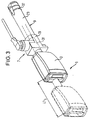
- the seat belt system 1 shown in FIGS. 2 and 3 is, in particular, axially much smaller than that shown in FIG. 1, since the directions of movement of the belt buckle 3 and the piston of a piston / cylinder unit 9 arranged in the cylinder 23 match.
- the direction of movement of the belt buckle 3 is indicated by the arrow denoted by R when the back tensioning device 7 is actuated.
- the latter At the end of the cylinder 23 opposite the belt buckle 3, the latter has an external thread 37 on its outer surface, by means of which the tightening device 7 together with the belt buckle 3 can be screwed into a corresponding threaded hole in the vehicle floor, so that only a part of the cylinder 23 is removed from it protrudes the vehicle interior.
- FIG. 3 the original position of the belt buckle 3 when the piston / cylinder unit 9 is not activated is shown with broken lines and the position of the belt buckle 3 after the activation of the piston / cylinder unit 9 is shown with solid lines.
- L1 is the maximum tensioning path. It can be seen here that the rope thimble 31, which connects the belt buckle 3 to the pull rope 5, penetrates the front side into the gas generator housing 19 when the tensioning device 7 is actuated, and even penetrates through it and also through an end wall of the cylinder 23 which cannot be seen in this view extends into the interior of the cylinder 23.
- the belt buckle 3 is shown with continuous lines when the rear tightening device 7 is not actuated and with broken lines when the rear tightening device 7 is actuated.
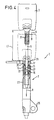
- the gas generator 11 is arranged in the interior of the cylinder 23, in which a cartridge-shaped gas generator housing 19 adjoins an end wall 35 of the cylinder 23.
- the end wall 35 is partly formed by the cylinder 23 and partly by a corresponding end wall of the gas generator housing 19, so that the back tensioning device 7 is axially shorter, since two axially adjacent end walls are not provided.
- the gas generator housing 19, which is arranged coaxially to the cylinder 23, has a central opening 33 through which the pull cable 5 extends to the piston 15, to which it is attached.
- a seal 27 surrounding the traction cable 5 is also provided.
- the pull cable 5 has a sheathing which has a circular-cylindrical outer peripheral surface.
- An annular ignition unit 17 with a central opening 21 adjoins the end wall 35 of the gas generator housing 19, through which the pull cable 5 extends to the piston 15.
- the ignition unit 17 can also be U-shaped or semicircular.
- the cylinder 23 is locked on the vehicle body or a vehicle seat via a laterally protruding fastening tab 25 formed on the lateral surface of the cylinder 23.
- the fastening tab 25 allows the cylinder 23 to pivot slightly so that it can adapt slightly to the direction of the seat belt.
- the piston 15 pulls the belt buckle 3 in the direction R to the cylinder 23 via the traction cable 5, with the cable thimble 31 at the end of this movement and the end wall 35 of the gas generator housing 19, which also forms the end wall of the cylinder 23, penetrates.
- the rope thimble 31 thus extends into the interior of the cylinder 23.
- the third embodiment of the seat belt system 1 shown in FIG. 5 essentially corresponds to the embodiment shown in FIG. 4, the difference being that the ignition unit 21 is fastened to the cylinder jacket and has a side opening in this and in the gas generator housing 19 arranged inside the cylinder 23 the space containing pyrotechnic material communicates. As a result, the seat belt system 1 is axially shorter. In addition, to limit the tensioning path L2, the housing of the belt buckle 3 can strike the end wall 35 of the piston / cylinder unit 9.
- the gas generator housing 19 is formed exclusively by correspondingly shaped wall parts of the cylinder 23.
- FIGS. 2 to 5 The embodiments of the seat belt system 1 shown in FIGS. 2 to 5 are distinguished by the same tensioning path in comparison to the known one shown in FIG. 1 Seat belt system from a much more compact, especially axially shorter design.
- FIGS. 6 to 11 Alternative fastening options for the cylinder 23 are shown in FIGS. 6 to 11.
- the cylinder 23 is screwed with its external thread 37 into an opening in the vehicle floor 39.
- the cylinder 23 penetrates the vehicle floor 39 and projects downward.
- a protective cap 41 on the downwardly projecting end of the cylinder 23 protects it.
- the lower end of the cylinder 23 and the protective cap 41 are matched to one another so that when the back tensioning device is activated, the protective cap 41 is blown off by the piston moving downward or the air displaced thereby, so that the required overall length of the cylinder 23 can be shortened.
- the fastening option shown in FIG. 7 is characterized in that the cylinder 23 is installed in a recess 43 formed in the vehicle floor 39, so that the cylinder is better protected from the vehicle floor.
- the lower end of the cylinder 23 is equipped with two extensions 45, which are part of a bayonet catch.
- the corresponding opposite consists of a sleeve 47 fastened in a hole in the vehicle floor 39 with a corresponding opening 49 through which the cylinder 23 can be inserted into the sleeve 47.
- FIGS. 10 and 11 Another cost-effective way of fastening the cylinder to the vehicle body or to a vehicle seat is shown in FIGS. 10 and 11.
- the rear end 53 of the cylinder 23 is compressed into a two-layer plate, which is provided with an opening 57, via which the cylinder 23 can be attached to the seat frame 55.
- the rear end 53 can be curved in order to reach a fastening point that is more difficult to access or, as shown in FIG. 11, can run in a straight line.
- At least one exhaust air bore 59 can also be provided in the region of the not yet compressed end of the cylinder 23, through which the air displaced by the piston can flow out, so that the piston counteracts as little resistance as possible during its displacement.
Landscapes
- Engineering & Computer Science (AREA)
- Mechanical Engineering (AREA)
- Physics & Mathematics (AREA)
- Fluid Mechanics (AREA)
- General Engineering & Computer Science (AREA)
- Analytical Chemistry (AREA)
- Chemical & Material Sciences (AREA)
- Automotive Seat Belt Assembly (AREA)
- Body Structure For Vehicles (AREA)
- Devices For Conveying Motion By Means Of Endless Flexible Members (AREA)
- Seats For Vehicles (AREA)
- General Details Of Gearings (AREA)
- Prostheses (AREA)
- Manufacture Of Alloys Or Alloy Compounds (AREA)
- Cooling, Air Intake And Gas Exhaust, And Fuel Tank Arrangements In Propulsion Units (AREA)
Applications Claiming Priority (2)
| Application Number | Priority Date | Filing Date | Title |
|---|---|---|---|
| DE29607362U DE29607362U1 (de) | 1996-04-23 | 1996-04-23 | Sicherheitsgurtsystem |
| DE29607362U | 1996-04-23 |
Publications (2)
| Publication Number | Publication Date |
|---|---|
| EP0803412A1 true EP0803412A1 (fr) | 1997-10-29 |
| EP0803412B1 EP0803412B1 (fr) | 2001-12-12 |
Family
ID=8023001
Family Applications (3)
| Application Number | Title | Priority Date | Filing Date |
|---|---|---|---|
| EP97106714A Expired - Lifetime EP0803412B1 (fr) | 1996-04-23 | 1997-04-23 | Système de ceinture de sécurité |
| EP97921726A Expired - Lifetime EP0889811B1 (fr) | 1996-04-23 | 1997-04-23 | Tendeur de sangle et dispositif pour sa fixation |
| EP97920743A Expired - Lifetime EP0889810B1 (fr) | 1996-04-23 | 1997-04-23 | Vehicule equipe d'un tendeur de sangle fixe au plancher de ce vehicule |
Family Applications After (2)
| Application Number | Title | Priority Date | Filing Date |
|---|---|---|---|
| EP97921726A Expired - Lifetime EP0889811B1 (fr) | 1996-04-23 | 1997-04-23 | Tendeur de sangle et dispositif pour sa fixation |
| EP97920743A Expired - Lifetime EP0889810B1 (fr) | 1996-04-23 | 1997-04-23 | Vehicule equipe d'un tendeur de sangle fixe au plancher de ce vehicule |
Country Status (10)
| Country | Link |
|---|---|
| US (3) | US6206423B1 (fr) |
| EP (3) | EP0803412B1 (fr) |
| JP (2) | JP2942742B2 (fr) |
| KR (1) | KR100247452B1 (fr) |
| CN (1) | CN1167705A (fr) |
| BR (1) | BR9701918A (fr) |
| CZ (1) | CZ286085B6 (fr) |
| DE (4) | DE29607362U1 (fr) |
| ES (2) | ES2127173T3 (fr) |
| WO (2) | WO1997039922A1 (fr) |
Cited By (1)
| Publication number | Priority date | Publication date | Assignee | Title |
|---|---|---|---|---|
| EP0806325B1 (fr) * | 1996-05-06 | 2001-04-11 | TRW Occupant Restraint Systems GmbH & Co. KG | Tendeur de ceinture |
Families Citing this family (20)
| Publication number | Priority date | Publication date | Assignee | Title |
|---|---|---|---|---|
| DE29609054U1 (de) * | 1996-05-20 | 1996-09-19 | Trw Occupant Restraint Systems Gmbh, 73551 Alfdorf | Gurtstraffer für ein Fahrzeuginsassen-Rückhaltesystem |
| DE29607362U1 (de) * | 1996-04-23 | 1996-08-22 | Trw Occupant Restraint Systems Gmbh, 73551 Alfdorf | Sicherheitsgurtsystem |
| DE29707352U1 (de) * | 1997-04-23 | 1997-08-21 | Trw Occupant Restraint Systems Gmbh, 73551 Alfdorf | Straffer für einen Sicherheitsgurt |
| DE29708880U1 (de) * | 1997-05-20 | 1997-09-18 | TRW Occupant Restraint Systems GmbH, 73553 Alfdorf | Gurtstraffer für ein Fahrzeuginsassen-Rückhaltesystem |
| GB2330334A (en) * | 1997-06-02 | 1999-04-21 | Alliedsignal Ltd | Buckle pretensioner for a vehicle |
| DE29720213U1 (de) * | 1997-11-14 | 1998-01-02 | Trw Occupant Restraint Systems Gmbh, 73551 Alfdorf | Schloßstraffer |
| US6076856A (en) * | 1999-01-12 | 2000-06-20 | General Motors Corporation | Belt tension and energy absorbing apparatus |
| US6264281B1 (en) * | 1999-08-25 | 2001-07-24 | Daimlerchrysler Corporation | Seat belt buckle pretensioner mounting mechanism |
| JP4656556B2 (ja) * | 2001-08-10 | 2011-03-23 | タカタ株式会社 | プリテンショナー |
| JP4138652B2 (ja) | 2001-08-23 | 2008-08-27 | 日本発条株式会社 | シートベルトプリテンショナ装置 |
| JP4708643B2 (ja) * | 2001-09-28 | 2011-06-22 | 日本発條株式会社 | 動力発生装置 |
| DE10213065A1 (de) * | 2002-03-18 | 2003-10-02 | Takata Petri Gmbh Ulm | Sicherheitsgurtvorrichtung |
| DE10257957B4 (de) | 2002-12-12 | 2019-06-27 | Volkswagen Ag | Hinteres Rückhaltesystem an Kraftfahrzeugen |
| DE20312222U1 (de) * | 2003-08-07 | 2003-12-18 | Trw Occupant Restraint Systems Gmbh & Co. Kg | Vorrichtung zum Straffen eines Sicherheitsgurts mit pyrotechnischem Linearantrieb |
| DE102004034006A1 (de) * | 2004-07-14 | 2006-02-02 | Iro Ab | Tensiometer |
| DE102011106514B4 (de) * | 2011-06-15 | 2021-08-12 | Zf Airbag Germany Gmbh | Pyrotechnischer Aktuator mit Entlüftung, Motorhaubenaufsteller und Gurtstraffer mit einem solchen Aktuator |
| JP5986152B2 (ja) * | 2014-07-30 | 2016-09-06 | トヨタ自動車株式会社 | リフトアップバックル装置 |
| DE102020103157B4 (de) * | 2020-02-07 | 2023-06-22 | Autoliv Development Ab | Straffvorrichtung für eine Sicherheitsgurtkomponente |
| CN113511170B (zh) * | 2020-04-10 | 2022-10-25 | 采埃孚汽车科技(上海)有限公司 | 通过汽车安全带增强司乘人员安全性的系统和方法 |
| KR102847065B1 (ko) * | 2023-11-17 | 2025-08-18 | 주식회사 우신세이프티시스템 | 가스 배출을 제한하는 구조를 포함한 랩 프리텐셔너 |
Citations (3)
| Publication number | Priority date | Publication date | Assignee | Title |
|---|---|---|---|---|
| US4258934A (en) * | 1978-05-23 | 1981-03-31 | Nippon Soken, Inc. | Seat belt tensioning device |
| US4458921A (en) * | 1981-08-12 | 1984-07-10 | Toyota Jidosha Kabushiki Kaisha | Seat belt tensioning device |
| DE4020600A1 (de) * | 1989-06-28 | 1991-01-03 | Autoliv Kolb Gmbh & Co | Gurtstrammer |
Family Cites Families (29)
| Publication number | Priority date | Publication date | Assignee | Title |
|---|---|---|---|---|
| US2239125A (en) * | 1939-06-20 | 1941-04-22 | Summers J Mills | Fastener |
| US2282360A (en) * | 1940-04-23 | 1942-05-12 | Walter E Horrocks | Lock washer for retaining pins in couplings |
| US2423432A (en) * | 1941-09-24 | 1947-07-08 | Scovill Manufacturing Co | Method of making composite metal coupling members |
| US3440602A (en) * | 1966-04-26 | 1969-04-22 | Gen Motors Corp | Seat belt tension indicator |
| FR1566533A (fr) * | 1968-03-14 | 1969-05-09 | ||
| FR1590334A (fr) * | 1968-10-30 | 1970-04-13 | ||
| IT939351B (it) | 1970-08-17 | 1973-02-10 | Kangol Magnet Ltd | Dispositivo di montaggio per cintu re di sicurezza in particolare per autoveicoli |
| GB1351447A (en) | 1970-08-17 | 1974-05-01 | Kangol Magnet Ltd | Mounting of a vehicle safety belt buckle part |
| DE2159265A1 (de) * | 1971-11-30 | 1973-06-07 | Daimler Benz Ag | Rueckhaltevorrichtung fuer die insassen von fahrzeugen, insbesondere kraftfahrzeugen |
| US3942819A (en) * | 1972-05-12 | 1976-03-09 | Volkswagenwerk Aktiengesellschaft | Safety belt tensioning device |
| DE2223061A1 (de) * | 1972-05-12 | 1973-11-22 | Volkswagenwerk Ag | Spanneinrichtung fuer rueckhalteeinrichtungen |
| FR2213231B1 (fr) * | 1972-11-06 | 1976-08-20 | Peugeot & Renault | |
| JPS49125430U (fr) * | 1973-02-26 | 1974-10-26 | ||
| FR2239870A1 (fr) * | 1973-08-03 | 1975-02-28 | Poudres & Explosifs Ste Nale | |
| GB1571505A (en) | 1977-04-07 | 1980-07-16 | Kangol Magnet Ltd | Cable attachment fittings |
| JPS56116056U (fr) * | 1980-02-04 | 1981-09-05 | ||
| EP0205901B1 (fr) * | 1985-05-21 | 1989-09-13 | Autoflug GmbH & Co Fahrzeugtechnik | Dispositif de ceinture de sécurité, en particulier pour véhicules à moteur |
| JPH0369561U (fr) * | 1989-11-10 | 1991-07-10 | ||
| JPH0446844A (ja) * | 1990-06-13 | 1992-02-17 | Takata Kk | シートベルト装置のメカニカルセンサー |
| EP0558963B1 (fr) * | 1992-03-05 | 1997-10-01 | TRW Occupant Restraint Systems GmbH | Dispositif tendeur linéaire pour un système de retenue dans un véhicule |
| DE4221245C1 (de) * | 1992-06-27 | 1993-10-07 | Daimler Benz Ag | Sicherheitsgurtbefestigung an einem Haltebeschlag |
| DE4232569C2 (de) * | 1992-09-29 | 1995-10-05 | Autoflug Gmbh | Pyrotechnische Sicherheitsgurt-Strammvorrichtung |
| US5368427A (en) * | 1993-02-08 | 1994-11-29 | General Motors Corporation | Quarter turn fastener |
| US5366245A (en) * | 1993-12-10 | 1994-11-22 | Trw Vehicle Safety Systems Inc. | Linear buckle pretensioner device |
| DE4404462A1 (de) * | 1994-02-11 | 1995-08-17 | Trw Repa Gmbh | Gurtstraffer für einen Sicherheitsgurt |
| US5568940A (en) * | 1994-07-27 | 1996-10-29 | Trw Vehicle Safety Systems Inc. | Belt tightener for a vehicle safety belt system |
| US5639120A (en) * | 1995-09-27 | 1997-06-17 | Ford Motor Company | Seat belt buckle pretensioner with end cap |
| DE29607362U1 (de) * | 1996-04-23 | 1996-08-22 | Trw Occupant Restraint Systems Gmbh, 73551 Alfdorf | Sicherheitsgurtsystem |
| US5887897A (en) * | 1997-02-06 | 1999-03-30 | Breed Automoive Technology, Inc. | Apparatus for pretensioning a vehicular seat belt |
-
1996
- 1996-04-23 DE DE29607362U patent/DE29607362U1/de not_active Expired - Lifetime
-
1997
- 1997-04-22 CZ CZ19971216A patent/CZ286085B6/cs not_active IP Right Cessation
- 1997-04-22 CN CN97110776A patent/CN1167705A/zh active Pending
- 1997-04-22 JP JP9104864A patent/JP2942742B2/ja not_active Expired - Fee Related
- 1997-04-22 KR KR1019970014819A patent/KR100247452B1/ko not_active Expired - Fee Related
- 1997-04-23 JP JP9537750A patent/JP2000508986A/ja active Pending
- 1997-04-23 US US09/171,585 patent/US6206423B1/en not_active Expired - Fee Related
- 1997-04-23 EP EP97106714A patent/EP0803412B1/fr not_active Expired - Lifetime
- 1997-04-23 DE DE59705726T patent/DE59705726D1/de not_active Expired - Lifetime
- 1997-04-23 WO PCT/EP1997/002076 patent/WO1997039922A1/fr not_active Ceased
- 1997-04-23 ES ES97920743T patent/ES2127173T3/es not_active Expired - Lifetime
- 1997-04-23 BR BR9701918A patent/BR9701918A/pt not_active Application Discontinuation
- 1997-04-23 DE DE59701313T patent/DE59701313D1/de not_active Expired - Fee Related
- 1997-04-23 US US09/171,503 patent/US6213509B1/en not_active Expired - Fee Related
- 1997-04-23 EP EP97921726A patent/EP0889811B1/fr not_active Expired - Lifetime
- 1997-04-23 ES ES97106714T patent/ES2109903T3/es not_active Expired - Lifetime
- 1997-04-23 US US08/842,153 patent/US5927756A/en not_active Expired - Fee Related
- 1997-04-23 DE DE59702239T patent/DE59702239D1/de not_active Expired - Fee Related
- 1997-04-23 WO PCT/EP1997/002068 patent/WO1997039921A1/fr not_active Ceased
- 1997-04-23 EP EP97920743A patent/EP0889810B1/fr not_active Expired - Lifetime
Patent Citations (3)
| Publication number | Priority date | Publication date | Assignee | Title |
|---|---|---|---|---|
| US4258934A (en) * | 1978-05-23 | 1981-03-31 | Nippon Soken, Inc. | Seat belt tensioning device |
| US4458921A (en) * | 1981-08-12 | 1984-07-10 | Toyota Jidosha Kabushiki Kaisha | Seat belt tensioning device |
| DE4020600A1 (de) * | 1989-06-28 | 1991-01-03 | Autoliv Kolb Gmbh & Co | Gurtstrammer |
Cited By (1)
| Publication number | Priority date | Publication date | Assignee | Title |
|---|---|---|---|---|
| EP0806325B1 (fr) * | 1996-05-06 | 2001-04-11 | TRW Occupant Restraint Systems GmbH & Co. KG | Tendeur de ceinture |
Also Published As
| Publication number | Publication date |
|---|---|
| BR9701918A (pt) | 1998-11-10 |
| JP2000508986A (ja) | 2000-07-18 |
| EP0889811A1 (fr) | 1999-01-13 |
| ES2109903T3 (es) | 2002-07-16 |
| US6213509B1 (en) | 2001-04-10 |
| ES2109903T1 (es) | 1998-02-01 |
| CZ286085B6 (cs) | 2000-01-12 |
| KR100247452B1 (ko) | 2000-05-01 |
| EP0889810B1 (fr) | 2000-08-23 |
| DE59701313D1 (de) | 2000-04-27 |
| ES2127173T1 (es) | 1999-04-16 |
| DE29607362U1 (de) | 1996-08-22 |
| JPH1035412A (ja) | 1998-02-10 |
| KR970069665A (ko) | 1997-11-07 |
| EP0889810A1 (fr) | 1999-01-13 |
| JP2942742B2 (ja) | 1999-08-30 |
| US6206423B1 (en) | 2001-03-27 |
| DE59702239D1 (de) | 2000-09-28 |
| EP0803412B1 (fr) | 2001-12-12 |
| US5927756A (en) | 1999-07-27 |
| ES2127173T3 (es) | 2000-12-16 |
| WO1997039921A1 (fr) | 1997-10-30 |
| DE59705726D1 (de) | 2002-01-24 |
| CN1167705A (zh) | 1997-12-17 |
| CZ121697A3 (en) | 1997-11-12 |
| WO1997039922A1 (fr) | 1997-10-30 |
| EP0889811B1 (fr) | 2000-03-22 |
Similar Documents
| Publication | Publication Date | Title |
|---|---|---|
| EP0803412B1 (fr) | Système de ceinture de sécurité | |
| DE19882814C2 (de) | Gurtstraffer | |
| DE602004001935T2 (de) | Stellglied | |
| EP0568996B1 (fr) | Entraînement linéaire pour tendeur de ceinture de sécurité | |
| DE60314297T2 (de) | Vorrichtung zur überwachung von airbagentfaltung | |
| DE102008028921B4 (de) | Gassackmodul für ein Fahrzeug-Sicherheitssystem | |
| DE29707352U1 (de) | Straffer für einen Sicherheitsgurt | |
| DE4310173A1 (de) | Aufblaseinrichtungsanbringungsstruktur für ein Fahrzeuginsassen-Luftsacksystem, insbesondere für ein Fahrgast-Luftsacksystem | |
| DE20102758U1 (de) | Gurtstraffer | |
| DE4224324C2 (de) | Gurtstraffer | |
| DE29904404U1 (de) | Gurtstraffersystem | |
| WO2000003897A1 (fr) | Module de retenue pour un vehicule a moteur | |
| DE3718117A1 (de) | Gurtstrammer fuer einen fahrzeug-sicherheitsgurt | |
| DE29608213U1 (de) | Gurtstraffer für einen Sicherheitsgurt | |
| DE19633696B4 (de) | Airbagabdeckklappe | |
| EP1048040B1 (fr) | Dispositif d'operation manuelle d'urgence pour aimants de commutation | |
| DE69906664T2 (de) | Kraftstoff- Einfülleinlassanordnung | |
| DE69909129T2 (de) | Sicherheitsgurt-aufroller | |
| EP1078827B1 (fr) | Dispositif pour tendre une ceinture de sécurité sur un enrouleur | |
| DE2946717A1 (de) | Vorrichtung zum spannen eines gurts | |
| DE69909372T2 (de) | Zunge für einen aufblasbaren Sicherheitsgürtel und aufblasbarer Sicherheitsgürtel | |
| DE2535538B2 (de) | Bremsdrucksteuerventil | |
| DE60317899T2 (de) | Vorspanner | |
| DE69706694T2 (de) | Strammvorrichtung | |
| DE20007238U1 (de) | Gurtaufroller für einen Fahrzeug-Sicherheitsgurt |
Legal Events
| Date | Code | Title | Description |
|---|---|---|---|
| PUAI | Public reference made under article 153(3) epc to a published international application that has entered the european phase |
Free format text: ORIGINAL CODE: 0009012 |
|
| AK | Designated contracting states |
Kind code of ref document: A1 Designated state(s): DE ES FR GB IT SE |
|
| ITCL | It: translation for ep claims filed |
Representative=s name: DR. ING. A. RACHELI & C. |
|
| EL | Fr: translation of claims filed | ||
| GBC | Gb: translation of claims filed (gb section 78(7)/1977) | ||
| REG | Reference to a national code |
Ref country code: ES Ref legal event code: BA2A Ref document number: 2109903 Country of ref document: ES Kind code of ref document: T1 |
|
| 17P | Request for examination filed |
Effective date: 19971222 |
|
| RAP1 | Party data changed (applicant data changed or rights of an application transferred) |
Owner name: TRW OCCUPANT RESTRAINT SYSTEMS GMBH & CO. KG |
|
| 17Q | First examination report despatched |
Effective date: 19990616 |
|
| GRAG | Despatch of communication of intention to grant |
Free format text: ORIGINAL CODE: EPIDOS AGRA |
|
| GRAG | Despatch of communication of intention to grant |
Free format text: ORIGINAL CODE: EPIDOS AGRA |
|
| GRAH | Despatch of communication of intention to grant a patent |
Free format text: ORIGINAL CODE: EPIDOS IGRA |
|
| GRAH | Despatch of communication of intention to grant a patent |
Free format text: ORIGINAL CODE: EPIDOS IGRA |
|
| GRAA | (expected) grant |
Free format text: ORIGINAL CODE: 0009210 |
|
| AK | Designated contracting states |
Kind code of ref document: B1 Designated state(s): DE ES FR GB IT SE |
|
| REG | Reference to a national code |
Ref country code: GB Ref legal event code: IF02 |
|
| REF | Corresponds to: |
Ref document number: 59705726 Country of ref document: DE Date of ref document: 20020124 |
|
| PG25 | Lapsed in a contracting state [announced via postgrant information from national office to epo] |
Ref country code: SE Free format text: LAPSE BECAUSE OF FAILURE TO SUBMIT A TRANSLATION OF THE DESCRIPTION OR TO PAY THE FEE WITHIN THE PRESCRIBED TIME-LIMIT Effective date: 20020312 |
|
| PGFP | Annual fee paid to national office [announced via postgrant information from national office to epo] |
Ref country code: GB Payment date: 20020315 Year of fee payment: 6 |
|
| GBT | Gb: translation of ep patent filed (gb section 77(6)(a)/1977) |
Effective date: 20020227 |
|
| ET | Fr: translation filed | ||
| PGFP | Annual fee paid to national office [announced via postgrant information from national office to epo] |
Ref country code: ES Payment date: 20020412 Year of fee payment: 6 |
|
| REG | Reference to a national code |
Ref country code: ES Ref legal event code: FG2A Ref document number: 2109903 Country of ref document: ES Kind code of ref document: T3 |
|
| PLBE | No opposition filed within time limit |
Free format text: ORIGINAL CODE: 0009261 |
|
| STAA | Information on the status of an ep patent application or granted ep patent |
Free format text: STATUS: NO OPPOSITION FILED WITHIN TIME LIMIT |
|
| 26N | No opposition filed | ||
| PG25 | Lapsed in a contracting state [announced via postgrant information from national office to epo] |
Ref country code: GB Free format text: LAPSE BECAUSE OF NON-PAYMENT OF DUE FEES Effective date: 20030423 |
|
| PG25 | Lapsed in a contracting state [announced via postgrant information from national office to epo] |
Ref country code: ES Free format text: LAPSE BECAUSE OF NON-PAYMENT OF DUE FEES Effective date: 20030424 |
|
| GBPC | Gb: european patent ceased through non-payment of renewal fee |
Effective date: 20030423 |
|
| REG | Reference to a national code |
Ref country code: ES Ref legal event code: FD2A Effective date: 20030424 |
|
| PGFP | Annual fee paid to national office [announced via postgrant information from national office to epo] |
Ref country code: FR Payment date: 20050401 Year of fee payment: 9 |
|
| PGFP | Annual fee paid to national office [announced via postgrant information from national office to epo] |
Ref country code: IT Payment date: 20060430 Year of fee payment: 10 |
|
| REG | Reference to a national code |
Ref country code: FR Ref legal event code: ST Effective date: 20061230 |
|
| PG25 | Lapsed in a contracting state [announced via postgrant information from national office to epo] |
Ref country code: FR Free format text: LAPSE BECAUSE OF NON-PAYMENT OF DUE FEES Effective date: 20060502 |
|
| PG25 | Lapsed in a contracting state [announced via postgrant information from national office to epo] |
Ref country code: IT Free format text: LAPSE BECAUSE OF NON-PAYMENT OF DUE FEES Effective date: 20070423 |
|
| PGFP | Annual fee paid to national office [announced via postgrant information from national office to epo] |
Ref country code: DE Payment date: 20160430 Year of fee payment: 20 |
|
| REG | Reference to a national code |
Ref country code: DE Ref legal event code: R071 Ref document number: 59705726 Country of ref document: DE |