EP0803426A1 - Train de roulement, notamment bogie - Google Patents
Train de roulement, notamment bogie Download PDFInfo
- Publication number
- EP0803426A1 EP0803426A1 EP96106712A EP96106712A EP0803426A1 EP 0803426 A1 EP0803426 A1 EP 0803426A1 EP 96106712 A EP96106712 A EP 96106712A EP 96106712 A EP96106712 A EP 96106712A EP 0803426 A1 EP0803426 A1 EP 0803426A1
- Authority
- EP
- European Patent Office
- Prior art keywords
- connecting rods
- links
- chassis according
- damped
- handlebars
- Prior art date
- Legal status (The legal status is an assumption and is not a legal conclusion. Google has not performed a legal analysis and makes no representation as to the accuracy of the status listed.)
- Granted
Links
- 239000000725 suspension Substances 0.000 claims description 3
- 238000013016 damping Methods 0.000 claims 2
- 230000001105 regulatory effect Effects 0.000 claims 1
- 239000006096 absorbing agent Substances 0.000 description 1
- 238000010276 construction Methods 0.000 description 1
- 230000000694 effects Effects 0.000 description 1
- 230000035939 shock Effects 0.000 description 1
Images
Classifications
-
- B—PERFORMING OPERATIONS; TRANSPORTING
- B61—RAILWAYS
- B61F—RAIL VEHICLE SUSPENSIONS, e.g. UNDERFRAMES, BOGIES OR ARRANGEMENTS OF WHEEL AXLES; RAIL VEHICLES FOR USE ON TRACKS OF DIFFERENT WIDTH; PREVENTING DERAILING OF RAIL VEHICLES; WHEEL GUARDS, OBSTRUCTION REMOVERS OR THE LIKE FOR RAIL VEHICLES
- B61F5/00—Constructional details of bogies; Connections between bogies and vehicle underframes; Arrangements or devices for adjusting or allowing self-adjustment of wheel axles or bogies when rounding curves
- B61F5/38—Arrangements or devices for adjusting or allowing self- adjustment of wheel axles or bogies when rounding curves, e.g. sliding axles, swinging axles
-
- B—PERFORMING OPERATIONS; TRANSPORTING
- B61—RAILWAYS
- B61F—RAIL VEHICLE SUSPENSIONS, e.g. UNDERFRAMES, BOGIES OR ARRANGEMENTS OF WHEEL AXLES; RAIL VEHICLES FOR USE ON TRACKS OF DIFFERENT WIDTH; PREVENTING DERAILING OF RAIL VEHICLES; WHEEL GUARDS, OBSTRUCTION REMOVERS OR THE LIKE FOR RAIL VEHICLES
- B61F5/00—Constructional details of bogies; Connections between bogies and vehicle underframes; Arrangements or devices for adjusting or allowing self-adjustment of wheel axles or bogies when rounding curves
- B61F5/02—Arrangements permitting limited transverse relative movements between vehicle underframe or bolster and bogie; Connections between underframes and bogies
- B61F5/16—Centre bearings or other swivel connections between underframes and bolsters or bogies
Definitions
- the invention relates to a chassis with at least one sprung axle or shaft, in particular bogie, for rail vehicles, such as. B. funiculars.
- Such trolleys are known from WO 89/12566 and EP 0365 489 A2 and have the disadvantage that heavy bogie frames are required and that complicated devices have to be arranged for comfortable transverse suspension and for self-steering of the axles. If the substructure is poor, deviations from the ideal rail position lead to bogie deformation or reduced driving comfort and increased wear.
- the invention has set itself the task of addressing the disadvantages mentioned and to create a lightweight design for chassis. Due to the use of radially displaceable spring-damper elements, which are located on the side or above the wheels, the vertical forces are directed directly into the car body or into the bogie frame.
- the spring-damper elements are preferably air springs.
- the longitudinal and transverse forces are directed via spring-loaded or damped handlebars to the central pivot point or directly into the vehicle body.
- a major advantage is that in the invention, both the longitudinal and the transverse forces or their resilient effects are damped.
- the invention is characterized in that the barrel axis or the shaft are connected by radially arranged links and preferably by connecting rods arranged parallel to the track, whereby horizontal forces are guided undamped or damped into the pivot point in accordance with the design of the links and the connecting rods and that the vertical support of the wheels relative to the car body via the barrel axis or shaft or the connecting rods or the handlebars via spring elements, preferably air springs. Further essential features of the invention are specified in subclaims 2-8.
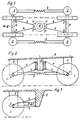
- FIGS. 1-3 show a bogie in elevation and plan and Fig. 3 shows the elevation of an axle bogie.
- Fig. 1 shows in the floor plan a bogie of a rail vehicle in which the individual running axles 6 are connected to the pivot 5 of the bogie via links 4 damped or sprung in the axial direction.
- the handlebars 4 are optionally sprung in the axial direction and / or damped and may have elastic connections 7, 7 'at their connections to the individual components 6 and 5 or the bolt connections are mounted in elastic sleeves, so that slight deformations within the connection during driving can be compensated.
- the links 4 can also be designed as shock absorbers.
- the running wheels 1 of the running axles 6 are supported in the vertical direction by spring-damper elements 2 (FIG. 2) which are designed, for example, as air springs.
- the single ones Impellers 1 of successive running axles 6 are connected by a resilient and / or damped connecting rod 3, which is formed, for example, by a telescopic tube, in particular sprung and / or damped in the axial direction, or a connecting rod with at least one elastically lined eye.
- Both the connecting rods 3 and the control arms 4 are arranged in pairs, the control arms 4 being inclined to one another in plan otherwise essentially parallel and the connection rods 3 of the running axles 6 being parallel to one another, in particular in the direction of travel 8.
- the links 4 are attached in an optimal embodiment to a sleeve 10 which is vertically displaceable in vertical direction on component 5 around the component 5 designed as a pivot, so that the vehicle weight is only via the springs 2 in the landing gear is inserted.
- both the connecting rods 3 and the handlebars 4 can be formed by rigid elements which have little freedom of movement at the bearing point.
- at least one of the components 3 or 4 is mounted with elastic connecting means, or is designed directly as a telescope, which enables larger spring travel. In most cases, lining the eyes with an elastic mass is sufficient.
- the spring stiffness or damper constant can be influenced by changing the hydraulic pressure in the individual damper elements, so that the inclination of the car body can be influenced during rapid cornering, for example by the Hydraulic pressure is reduced on the inside of the curve and increased on the outside of the curve compared to normal pressure.
- the maximum cornering speed can be increased by these measures.
- the arrangement of the handlebars in a triangle with respect to the central pivot point is essential, the handlebars also being able to be unsprung, for example by the connection bolts being mounted in elastic sleeves.
- the construction is not limited to the use of a bogie, it can also be used in single-axle undercarriages (FIG. 3), in which the links 4 are articulated at a central point in the car body 9 and the half connecting rods 3 between the car body 9 and the running axle 6 are.
- the running axis 6 adjusts itself to the rail conditions without major deformations being introduced into the car body or into the chassis frame.
- the invention enables a defined radial self-steering axle adjustment depending on the existing transverse force using spring-loaded and possibly damped connecting rods 3 and the handlebar arrangement described above. There is the possibility of superimposing the radial axle adjustment by appropriately controlling the handlebars or connecting rods. Due to the symmetrical design, the same components can be used for a bogie (with two running axles) as well as for an axle bogie (with one axle), with the latter connecting the halved connecting rods to the car body or the chassis frame in an articulated manner.
Landscapes
- Engineering & Computer Science (AREA)
- Mechanical Engineering (AREA)
- Vibration Prevention Devices (AREA)
- Handcart (AREA)
- Transition And Organic Metals Composition Catalysts For Addition Polymerization (AREA)
- Vehicle Body Suspensions (AREA)
- Toys (AREA)
Priority Applications (4)
| Application Number | Priority Date | Filing Date | Title |
|---|---|---|---|
| ES96106712T ES2145950T3 (es) | 1996-04-27 | 1996-04-27 | Tren de rodadura, especialmente para vehiculos sobre carriles. |
| AT96106712T ATE190574T1 (de) | 1996-04-27 | 1996-04-27 | Fahrwerk, insbesondere drehgestell |
| EP96106712A EP0803426B1 (fr) | 1996-04-27 | 1996-04-27 | Train de roulement, notamment bogie |
| DE59604686T DE59604686D1 (de) | 1996-04-27 | 1996-04-27 | Fahrwerk, insbesondere Drehgestell |
Applications Claiming Priority (1)
| Application Number | Priority Date | Filing Date | Title |
|---|---|---|---|
| EP96106712A EP0803426B1 (fr) | 1996-04-27 | 1996-04-27 | Train de roulement, notamment bogie |
Publications (2)
| Publication Number | Publication Date |
|---|---|
| EP0803426A1 true EP0803426A1 (fr) | 1997-10-29 |
| EP0803426B1 EP0803426B1 (fr) | 2000-03-15 |
Family
ID=8222726
Family Applications (1)
| Application Number | Title | Priority Date | Filing Date |
|---|---|---|---|
| EP96106712A Expired - Lifetime EP0803426B1 (fr) | 1996-04-27 | 1996-04-27 | Train de roulement, notamment bogie |
Country Status (4)
| Country | Link |
|---|---|
| EP (1) | EP0803426B1 (fr) |
| AT (1) | ATE190574T1 (fr) |
| DE (1) | DE59604686D1 (fr) |
| ES (1) | ES2145950T3 (fr) |
Cited By (5)
| Publication number | Priority date | Publication date | Assignee | Title |
|---|---|---|---|---|
| WO2001032490A1 (fr) * | 1999-11-03 | 2001-05-10 | Schaefer Enkeler Andreas | Bogie pour vehicules sur rails |
| WO2008145641A1 (fr) * | 2007-05-29 | 2008-12-04 | Bombardier Transportation Gmbh | Véhicule sur rails à suspension monoétage |
| EP2886412A1 (fr) * | 2013-10-15 | 2015-06-24 | Politechnika Warszawska | Système de connexion de trains de roues de bogie ferroviaire autodirecteur |
| EP3176048A4 (fr) * | 2014-07-31 | 2018-04-04 | Nippon Steel & Sumitomo Metal Corporation | Bogie pour matériel roulant et matériel roulant doté de celui-ci |
| CN111688750A (zh) * | 2020-06-30 | 2020-09-22 | 中车工业研究院有限公司 | 径向转向架 |
Citations (4)
| Publication number | Priority date | Publication date | Assignee | Title |
|---|---|---|---|---|
| US2861522A (en) * | 1956-11-13 | 1958-11-25 | Transit Res Corp | Light-weight rail truck |
| DE2049762A1 (de) * | 1969-10-13 | 1971-04-29 | British Railways Board, London | Schienenfahrzeug |
| EP0280040A2 (fr) * | 1987-02-26 | 1988-08-31 | MAN GHH Schienenverkehrstechnik GmbH | Train de roulement pour véhicule ferroviaire |
| EP0399345A1 (fr) * | 1989-05-24 | 1990-11-28 | Rautaruukki Oy | Construction de bogie pour un vehicule ferroviaire |
-
1996
- 1996-04-27 DE DE59604686T patent/DE59604686D1/de not_active Expired - Fee Related
- 1996-04-27 EP EP96106712A patent/EP0803426B1/fr not_active Expired - Lifetime
- 1996-04-27 AT AT96106712T patent/ATE190574T1/de active
- 1996-04-27 ES ES96106712T patent/ES2145950T3/es not_active Expired - Lifetime
Patent Citations (4)
| Publication number | Priority date | Publication date | Assignee | Title |
|---|---|---|---|---|
| US2861522A (en) * | 1956-11-13 | 1958-11-25 | Transit Res Corp | Light-weight rail truck |
| DE2049762A1 (de) * | 1969-10-13 | 1971-04-29 | British Railways Board, London | Schienenfahrzeug |
| EP0280040A2 (fr) * | 1987-02-26 | 1988-08-31 | MAN GHH Schienenverkehrstechnik GmbH | Train de roulement pour véhicule ferroviaire |
| EP0399345A1 (fr) * | 1989-05-24 | 1990-11-28 | Rautaruukki Oy | Construction de bogie pour un vehicule ferroviaire |
Cited By (5)
| Publication number | Priority date | Publication date | Assignee | Title |
|---|---|---|---|---|
| WO2001032490A1 (fr) * | 1999-11-03 | 2001-05-10 | Schaefer Enkeler Andreas | Bogie pour vehicules sur rails |
| WO2008145641A1 (fr) * | 2007-05-29 | 2008-12-04 | Bombardier Transportation Gmbh | Véhicule sur rails à suspension monoétage |
| EP2886412A1 (fr) * | 2013-10-15 | 2015-06-24 | Politechnika Warszawska | Système de connexion de trains de roues de bogie ferroviaire autodirecteur |
| EP3176048A4 (fr) * | 2014-07-31 | 2018-04-04 | Nippon Steel & Sumitomo Metal Corporation | Bogie pour matériel roulant et matériel roulant doté de celui-ci |
| CN111688750A (zh) * | 2020-06-30 | 2020-09-22 | 中车工业研究院有限公司 | 径向转向架 |
Also Published As
| Publication number | Publication date |
|---|---|
| EP0803426B1 (fr) | 2000-03-15 |
| ATE190574T1 (de) | 2000-04-15 |
| DE59604686D1 (de) | 2000-04-20 |
| ES2145950T3 (es) | 2000-07-16 |
Similar Documents
| Publication | Publication Date | Title |
|---|---|---|
| EP0565676B1 (fr) | Chassis pour wagons a plate-forme surbaissee | |
| EP0031008B1 (fr) | Bogie pour véhicules ferroviaires | |
| DE4311521C1 (de) | Wankstütze für Schienenfahrzeuge | |
| DE3610987C2 (fr) | ||
| EP1610995B1 (fr) | Train de roulement pour vehicule sur rails a meilleure suspension transversale | |
| DE102014205632A1 (de) | Einzelradaufhängung sowie Hinterachse mit Einzelradaufhängungen für ein Fahrzeug und entsprechend ausgestattetes Fahrzeug | |
| DE2027885A1 (de) | Achsaufhängung, insbesondere Hinterachs aufhangung von Kraftfahrzeugen | |
| DE19826448C2 (de) | Fahrwerk für ein Schienenfahrzeug | |
| EP1592570A1 (fr) | Suspension de roue destinee a des vehicules | |
| DE102014205635A1 (de) | Einzelradaufhängung sowie Hinterachse mit Einzelradaufhängungen für ein Fahrzeug und entsprechend ausgestattetes Fahrzeug | |
| EP0621165A1 (fr) | Train de roulement pour véhicules ferroviaires | |
| EP0649782B1 (fr) | Véhicule ferroviaire et train de roulement pour un tel véhicule | |
| EP0598353B1 (fr) | Train de roulement pour rames à plate-forme surbaissée | |
| DE202014101432U1 (de) | Einzelradaufhängung sowie Hinterachse mit Einzelradaufhängungen für ein Fahrzeug und entsprechend ausgestattetes Fahrzeug | |
| AT404010B (de) | Fahrwerk, insbesondere drehgestell für ein schienenfahrzeug wie z. b. für den wagen einer standseilbahn | |
| EP1955875A1 (fr) | Suspension de roue pour véhicules automobiles | |
| EP1123821A2 (fr) | Suspension à cinq bras pour une roue arrière de véhicule | |
| EP0803426B1 (fr) | Train de roulement, notamment bogie | |
| WO1991002673A1 (fr) | Chassis entraine a appareils de roulement individuels man×uvrables | |
| EP0507146B1 (fr) | Véhicule ferroviaire notamment véhicule à plancher bas | |
| DE69304236T2 (de) | Radaufhängungsvorrichtung für einen lenkbaren Vorderradsatz eines Nutzfahrzeuges | |
| EP2803514A1 (fr) | Dispositif de suspension | |
| EP1277603A2 (fr) | Suspension de roue indépendante multibras, en particulier suspension d'une roue avant directrice pour véhicule automobile | |
| EP0930210B1 (fr) | Train de roulement pour véhicules ferroviaires et véhicule ferroviaire avec au moins un tel train de roulement | |
| EP0692420B1 (fr) | Véhicule articulé avec un train de roulement à deux roues |
Legal Events
| Date | Code | Title | Description |
|---|---|---|---|
| PUAI | Public reference made under article 153(3) epc to a published international application that has entered the european phase |
Free format text: ORIGINAL CODE: 0009012 |
|
| AK | Designated contracting states |
Kind code of ref document: A1 Designated state(s): AT CH DE ES FR IT LI |
|
| 17P | Request for examination filed |
Effective date: 19970909 |
|
| 17Q | First examination report despatched |
Effective date: 19981210 |
|
| GRAG | Despatch of communication of intention to grant |
Free format text: ORIGINAL CODE: EPIDOS AGRA |
|
| GRAG | Despatch of communication of intention to grant |
Free format text: ORIGINAL CODE: EPIDOS AGRA |
|
| GRAG | Despatch of communication of intention to grant |
Free format text: ORIGINAL CODE: EPIDOS AGRA |
|
| GRAH | Despatch of communication of intention to grant a patent |
Free format text: ORIGINAL CODE: EPIDOS IGRA |
|
| GRAH | Despatch of communication of intention to grant a patent |
Free format text: ORIGINAL CODE: EPIDOS IGRA |
|
| GRAA | (expected) grant |
Free format text: ORIGINAL CODE: 0009210 |
|
| RAP1 | Party data changed (applicant data changed or rights of an application transferred) |
Owner name: LEITNER AUSTRIA GMBH |
|
| AK | Designated contracting states |
Kind code of ref document: B1 Designated state(s): AT CH DE ES FR IT LI |
|
| REF | Corresponds to: |
Ref document number: 190574 Country of ref document: AT Date of ref document: 20000415 Kind code of ref document: T |
|
| REG | Reference to a national code |
Ref country code: CH Ref legal event code: NV Representative=s name: ISLER & PEDRAZZINI AG Ref country code: CH Ref legal event code: EP |
|
| RAP2 | Party data changed (patent owner data changed or rights of a patent transferred) |
Owner name: LEITNER INTERNATIONAL B.V. |
|
| REF | Corresponds to: |
Ref document number: 59604686 Country of ref document: DE Date of ref document: 20000420 |
|
| ET | Fr: translation filed | ||
| ITF | It: translation for a ep patent filed | ||
| REG | Reference to a national code |
Ref country code: ES Ref legal event code: FG2A Ref document number: 2145950 Country of ref document: ES Kind code of ref document: T3 |
|
| REG | Reference to a national code |
Ref country code: CH Ref legal event code: PFA Free format text: LEITNER INTERNATIONAL B.V. TRANSFER- HIGH TECHNOLOGY INVESTMENTS B.V. |
|
| PLBE | No opposition filed within time limit |
Free format text: ORIGINAL CODE: 0009261 |
|
| STAA | Information on the status of an ep patent application or granted ep patent |
Free format text: STATUS: NO OPPOSITION FILED WITHIN TIME LIMIT |
|
| REG | Reference to a national code |
Ref country code: FR Ref legal event code: CD |
|
| REG | Reference to a national code |
Ref country code: ES Ref legal event code: PC2A |
|
| 26N | No opposition filed | ||
| REG | Reference to a national code |
Ref country code: CH Ref legal event code: PCAR Free format text: ISLER & PEDRAZZINI AG;POSTFACH 1772;8027 ZUERICH (CH) |
|
| PGFP | Annual fee paid to national office [announced via postgrant information from national office to epo] |
Ref country code: DE Payment date: 20090629 Year of fee payment: 14 |
|
| PG25 | Lapsed in a contracting state [announced via postgrant information from national office to epo] |
Ref country code: DE Free format text: LAPSE BECAUSE OF NON-PAYMENT OF DUE FEES Effective date: 20101103 |
|
| REG | Reference to a national code |
Ref country code: FR Ref legal event code: PLFP Year of fee payment: 20 |
|
| PGFP | Annual fee paid to national office [announced via postgrant information from national office to epo] |
Ref country code: ES Payment date: 20150310 Year of fee payment: 20 |
|
| PGFP | Annual fee paid to national office [announced via postgrant information from national office to epo] |
Ref country code: CH Payment date: 20150414 Year of fee payment: 20 |
|
| PGFP | Annual fee paid to national office [announced via postgrant information from national office to epo] |
Ref country code: FR Payment date: 20150408 Year of fee payment: 20 Ref country code: AT Payment date: 20150325 Year of fee payment: 20 Ref country code: IT Payment date: 20150422 Year of fee payment: 20 |
|
| REG | Reference to a national code |
Ref country code: CH Ref legal event code: PL |
|
| REG | Reference to a national code |
Ref country code: AT Ref legal event code: MK07 Ref document number: 190574 Country of ref document: AT Kind code of ref document: T Effective date: 20160427 |
|
| REG | Reference to a national code |
Ref country code: ES Ref legal event code: FD2A Effective date: 20160803 |
|
| PG25 | Lapsed in a contracting state [announced via postgrant information from national office to epo] |
Ref country code: ES Free format text: LAPSE BECAUSE OF EXPIRATION OF PROTECTION Effective date: 20160428 |