EP0803458B1 - Dispositif pour contrôler la position d'une bande en cours de défilement transversalement à la direction de défilement - Google Patents
Dispositif pour contrôler la position d'une bande en cours de défilement transversalement à la direction de défilement Download PDFInfo
- Publication number
- EP0803458B1 EP0803458B1 EP97106315A EP97106315A EP0803458B1 EP 0803458 B1 EP0803458 B1 EP 0803458B1 EP 97106315 A EP97106315 A EP 97106315A EP 97106315 A EP97106315 A EP 97106315A EP 0803458 B1 EP0803458 B1 EP 0803458B1
- Authority
- EP
- European Patent Office
- Prior art keywords
- pendulum
- axis
- roll
- tilting
- web
- Prior art date
- Legal status (The legal status is an assumption and is not a legal conclusion. Google has not performed a legal analysis and makes no representation as to the accuracy of the status listed.)
- Expired - Lifetime
Links
- 230000001154 acute effect Effects 0.000 claims description 6
- 230000005484 gravity Effects 0.000 claims description 4
- 230000001105 regulatory effect Effects 0.000 description 5
- 238000010276 construction Methods 0.000 description 4
- 239000000123 paper Substances 0.000 description 4
- 238000004519 manufacturing process Methods 0.000 description 2
- 239000004033 plastic Substances 0.000 description 2
- 229920001817 Agar Polymers 0.000 description 1
- 230000008878 coupling Effects 0.000 description 1
- 238000010168 coupling process Methods 0.000 description 1
- 238000005859 coupling reaction Methods 0.000 description 1
- 238000001514 detection method Methods 0.000 description 1
- 230000009189 diving Effects 0.000 description 1
- 238000005516 engineering process Methods 0.000 description 1
- 239000003365 glass fiber Substances 0.000 description 1
- 239000002649 leather substitute Substances 0.000 description 1
- 239000000463 material Substances 0.000 description 1
- 238000005259 measurement Methods 0.000 description 1
- 239000002184 metal Substances 0.000 description 1
- 239000002985 plastic film Substances 0.000 description 1
- 229920006255 plastic film Polymers 0.000 description 1
- 229920000728 polyester Polymers 0.000 description 1
- 239000000047 product Substances 0.000 description 1
- 230000004044 response Effects 0.000 description 1
- 230000004043 responsiveness Effects 0.000 description 1
- 239000005060 rubber Substances 0.000 description 1
- 239000011265 semifinished product Substances 0.000 description 1
- 230000035945 sensitivity Effects 0.000 description 1
- 230000003068 static effect Effects 0.000 description 1
- 239000004753 textile Substances 0.000 description 1
Images




Classifications
-
- B—PERFORMING OPERATIONS; TRANSPORTING
- B65—CONVEYING; PACKING; STORING; HANDLING THIN OR FILAMENTARY MATERIAL
- B65H—HANDLING THIN OR FILAMENTARY MATERIAL, e.g. SHEETS, WEBS, CABLES
- B65H23/00—Registering, tensioning, smoothing or guiding webs
- B65H23/02—Registering, tensioning, smoothing or guiding webs transversely
- B65H23/032—Controlling transverse register of web
- B65H23/038—Controlling transverse register of web by rollers
-
- B—PERFORMING OPERATIONS; TRANSPORTING
- B65—CONVEYING; PACKING; STORING; HANDLING THIN OR FILAMENTARY MATERIAL
- B65H—HANDLING THIN OR FILAMENTARY MATERIAL, e.g. SHEETS, WEBS, CABLES
- B65H2404/00—Parts for transporting or guiding the handled material
- B65H2404/10—Rollers
- B65H2404/15—Roller assembly, particular roller arrangement
- B65H2404/152—Arrangement of roller on a movable frame
- B65H2404/1526—Arrangement of roller on a movable frame both roller ends being journalled to be movable independently from each other
-
- B—PERFORMING OPERATIONS; TRANSPORTING
- B65—CONVEYING; PACKING; STORING; HANDLING THIN OR FILAMENTARY MATERIAL
- B65H—HANDLING THIN OR FILAMENTARY MATERIAL, e.g. SHEETS, WEBS, CABLES
- B65H2701/00—Handled material; Storage means
- B65H2701/10—Handled articles or webs
- B65H2701/17—Nature of material
- B65H2701/176—Cardboard
- B65H2701/1762—Corrugated
Definitions
- the invention relates to a device for position control of a running Track perpendicular to the running direction.
- running web should be there generally understood on the one hand any kind of goods, as they processed as a semi-finished product or in an intermediate production step as a web product such as Plastic films, plastic bags, magazines, synthetic leather, Paper webs in the production of corrugated cardboard etc.
- This term also includes endless belts, such as those e.g. as a so-called “screen” or “felt belt” in paper machines or as Conveyor belt are used in conveyor technology.
- so-called web guider are in different Embodiments known.
- so-called rotating frames are used, where two are parallel and at a distance from each other in the direction of web travel arranged guide rollers are arranged on a frame, which is about a vertical axis by a corresponding actuator
- Form of a pneumatic cylinder is rotatable. So that the two Guide rollers in a horizontal plane at a slight angle to the direction of web travel be set so that the running over the guide rollers A corresponding transverse offset is issued to the railway.
- the rotating frame position can continuously correct the transverse position of the web become.
- a web guiding system for straight-line control of endless belts such as transport and Sieve belts made of different materials, e.g. Plastic, rubber, Metal mesh, textile, etc. used that a tape guide role with an actuator, counter bearing and mechanical scanning by means of a roller lever.
- the tape guide roller is with its journal pivotable on one side in the counter bearing and on the other Side mounted in a combination bearing in a rotating, sliding manner.
- the combination warehouse is in turn arranged on a side of the belt to be guided Fixed actuator with which the tape guide roller around the counter bearing forming its pivot point can be pivoted on the other side is.
- the swivel movement is determined by the mechanical scanning of the Web edge regulated
- the guide roller is equipped with a special self-aligning bearing.
- This has a fixed center tube that is approximately vertical in the middle standing bolt.
- This pin forms a pendulum axis around which a shorter piece of pipe can swing back and forth horizontally.
- This Pipe piece carries ball bearings at both ends, around the an outer jacket tube made of glass fiber reinforced polyester can rotate.
- This jacket tube forms the actual guide roller.
- a disadvantage of the known guide roller is the fact that the Self-aligning bearing arranged relatively hidden inside the casing tube and is therefore difficult to assemble.
- the one described Bearing behavior resulting force on the center of the load-bearing Center tube concentrated so that the roller with larger working widths must have very large diameters for reasons of stability.
- this guide roller additionally one provide active position control if the response speed of the automatic regulation for the respective application is not sufficient.
- a pendulum roller is provided over the path to be controlled in its transverse position over a Wrap angle is guided and which has a rotating jacket.
- the mantle has two rotary bearings on two symmetrical ones Place the jacket tube, especially at the two roller ends an inner and opposite to the axis of rotation of the roll shell non-rotatable counter bearing part.
- This counter bearing part in which e.g. can be a pipe or a rod is again directly or symmetrically and articulated using a lever system Pendulum joint elements mounted, the two pendulum joint elements diametrically opposite with a radial distance from the axis of rotation are arranged.
- the invention has for its object a device to specify the position control of a running web transverse to the running direction, those with high responsiveness automatically effective, however can also be coupled with an active position control.
- the two pendulum joint elements thus define one Skewed pendulum axis for the pendulum roller, which is the axis of rotation in the
- the center of gravity cuts at an acute angle and in one plane runs with a vertical plane transverse to the direction of web travel an acute angle that opens in the direction of web travel
- the plane that receives the pendulum axis is in the direction of web travel tilted down, which is an important feature for the function the web guiding is. Otherwise cuts when using several Roll the pendulum axis that spanned by the axes of rotation of the rollers Level in their common focus
- the axis of symmetry of the continuous counter bearing part also coincides with the Rotation axis of the roller together or - in the case of several rollers - lies in the plane formed by the roller axes and is parallel to the roller axes.
- the pendulum roller is in an indifferent balance as long as the path to be guided is symmetrical runs over the pendulum roller. As soon as this from its target position runs out, the pendulum roller is loaded unevenly and tilts around inclined pendulum axis so that it is out of its horizontal position swung out and the band returned to the equilibrium position becomes. As found through practical trials, diving thereby the side of the pendulum roller towards which the web to be guided in Transverse direction runs out. Because of this tipping, the train is running up the pendulum roller so that the web is returned to the center and the pendulum roller is straightened.
- An advantage of the strip guiding system according to the invention is the fact that the rotary bearings are on both roller ends, so that the assembly effort is greatly reduced.
- the essential to the invention "Double self-aligning" by two diametrically opposed ones Pendulum joint elements for defining an inclined pendulum axis for a highly effective automatic web guiding. This is designed at the same time so that an active position control with a common position sensor for the transverse position of the to be controlled Web, a control device connected to the position sensor and one of which controlled actuator can be coupled. The latter can be done directly access the counter bearing part for pendulum adjustment of the pendulum roller, because this counter bearing part in the area of the roller ends - so practical freely accessible - lies. This is an important differentiator to the "Servo Roll" discussed above.
- a lever system is a rigid structure that acts as a carrier for one or several pendulum rollers. This inherently rigid structure is through the specified pendulum joint elements connected to the pendulum roller.
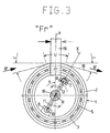
- the two radial struts 11, 12 run in diametrically opposite directions and are at an angle B to Vertical inclined.
- Your radial distance "e” from the axis of rotation R of the pendulum roller 1 can be 30 to 100 mm. The bigger “e” is, the higher the sensitivity of the following is even closer self-regulation described.
- the two central points M and N of the Ball joints 7, 8 forming pendulum joint elements define an oblique one Pendulum axis Q, which is the axis of rotation R in the center of gravity W intersects at an acute angle A and runs in a plane X which with a vertical plane Y lying transverse to the web running direction B ' includes the mentioned acute angle B, which extends in the web running direction B ' opens.
- the plane X is thus tilted in the web running direction B ' 3 becomes clear.
- FIG. 4 to 6 is a concrete structural design of the Shown schematically in FIG. 1 pendulum roller, wherein in FIG. 4th Dash-dotted lines indicate that the pendulum roller 1 for regulating the
- the transverse position of a revolving belt 20 is used, for example can be a pressure belt in a corrugated cardboard machine. The latter is guided around two deflection rollers 21, 22. The upper run 23 of the belt 20 is guided over the pendulum roller 1.
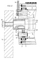
- the radial struts 11, 12 are also attached to a sleeve part 25, 26 which is rotationally fixed (rotation lock 27) sits on the axle strut 13.
- the latter shows almost the entire length of the Pendulum roller 1 on central tube 28, in the ends of which are cylindrical, stepped pins 29 are used, each of the sleeve parts 25, Record 26.
- the axle strut 13 is at the end with the bearing frame 14, 15 screwed (screws 30).
- the device shown in FIGS. 4 to 6 is also active Provide position control, which acts on the lever arm 19.
- This active Position control has on the one hand in the web running direction B 'in front of the Pendulum roller 1 arranged position sensor 31, which is, for example an electro-optical or pneumatic edge sensor can act as it is known from the prior art.
- FIG. 7 again differs of the embodiment according to FIGS. 4 to 6 essentially only in the design of the main camp. This is analogous to FIG. 2 here and 3 by stub axles 16, 17 screwed to the bearing frame 14, 15 formed on the one piece, the radial struts 11, 12 for the pendulum joint elements 7, 8 are formed. Otherwise there are matching construction parts again provided with identical reference numerals and require no further discussion.
- a normal series roller e.g. a guide roller for paper or corrugated cardboard
- a normal series roller e.g. a guide roller for paper or corrugated cardboard
- FIG. 11 corresponds functionally to that according to FIG 8 to 10. It was only the rigid assembly from the rotary bearing axis 35 and struts 38, 39 to form a complete frame 44 added. However, the two ball bearings 36, 37 are analogous to the aforementioned Embodiment arranged.
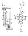
- FIG. 12 shows a double roller arrangement in which two are parallel at a distance from each other arranged rollers 45, 46 together on one Pendulum frame 47 are stored.
- the latter is analogous to frame 44 two ball bearings 36, 37 articulated.
- the pendulum axis defined by them Q in turn runs through the center of gravity W, which between the two rollers 45, 46.
- the pendulum frame arrangement 47 is with inlet and outlet sides Guide rollers 48, 49 combined.
Landscapes
- Registering, Tensioning, Guiding Webs, And Rollers Therefor (AREA)
- Replacement Of Web Rolls (AREA)
Claims (12)
- Dispositif pour réguler la position d'une bande (18, 20) en cours de défilement, transversalement à la direction (B') de défilement de ladite bande, comprenant au moins un rouleau compensateur (1, 45, 46)par l'intermédiaire duquel la bande (18, 20), dont la position transversale doit être régulée, est guidée selon un angle d'enlacement (U), etqui présente une enveloppe rotative (2)montée par l'intermédiaire de deux paliers de rotation (3, 4, 36, 37), en deux emplacements symétriques de la tubulure d'enveloppement, en particulier aux deux extrémités du rouleau, sur une pièce de portée complémentaire (5, 5', 5'', 35) occupant une position intérieure et ne pouvant pas tourner vis-à-vis de l'axe de rotation (R) de l'enveloppe (2) du rouleau,ladite pièce de portée complémentaire (5, 5', 5'', 35) étant à son tour montée symétriquement et de manière articulée, par l'intermédiaire d'éléments (7, 8) d'articulation pendulaire, directement ou au moyen d'un système à leviers (38, 39 ; 44 ; 47),sachant que lesdits éléments (7, 8) d'articulation pendulaireoccupent des positions fixes diamétralement opposées, à distance radiale vis-à-vis de l'axe de rotation (R) du rouleau compensateur (1), caractérisé par le fait queles éléments (7, 8) d'articulation pendulaire définissent par ailleurs,
associativement, un axe oblique d'oscillation (Q) qui coupe l'axe de rotation (R) selon un angle aigu (A), au centre de gravité (W) du rouleau, et qui s'étend dans un plan (X) décrivant, avec un plan vertical (Y) agencé transversalement par rapport à la direction (B') de défilement de la bande, un angle aigu (B) s'ouvrant dans ladite direction (B') de défilement de la bande. - Dispositif selon la revendication 1, caractérisé par le fait que l'enchaínement intégral non rotatif d'éléments, composé de la pièce de portée complémentaire (5, 5', 5", 35) et éventuellement du système à leviers (38, 39 ; 44 ; 47), situé entre les éléments (7, 8) d'articulation pendulaire et monté oscillant sur ces derniers, est fermement solidarisé de telle sorte qu'il forme un ensemble unitaire rigide.
- Dispositif selon la revendication 1 ou 2, caractérisé par le fait que l'angle (B), entre le plan (X) et le plan vertical (Y), mesure environ 30°.
- Dispositif selon l'une des revendications 1 à 3, caractérisé par le fait que l'angle d'enlacement (U) mesure d'environ 20 à 30°.
- Dispositif selon l'une des revendications 1 à 4, caractérisé par le fait que l'angle d'intersection (A) de l'axe d'oscillation (Q), avec l'axe de rotation (R), mesure d'environ 2° à 10° en fonction de la longueur du rouleau.
- Dispositif selon l'une des revendications 1 à 5, caractérisé par le fait qu'un rouleau compensateur (1) est monté rotatif, avec l'enveloppe (2) dudit rouleau, sur une tubulure commune de portée (5) respectivement fixée de manière articulée, par ses extrémités (6, 6'), à des articulations pendulaires réalisées sous la forme d'articulations sphériques (7, 8).
- Dispositif selon l'une des revendications 1 à 6, caractérisé par le fait que les articulations pendulaires (7, 8) sont respectivement situées sur des entretoises radiales (11, 12) faisant saillie, dans le sens radial, au-delà de paliers fixes principaux (13, 16, 17).
- Dispositif selon la revendication 7, caractérisé par le fait que les paliers principaux sont formés par une entretoise axiale fixe (13) parcourant le rouleau (1).
- Dispositif selon la revendication 7, caractérisé par le fait que les paliers principaux sont respectivement formés par des tourillons fixes (16, 17) pénétrant respectivement, de l'extérieur, dans l'enveloppe du rouleau.
- Dispositif selon l'une des revendications 1 à 5, caractérisé par le fait que le rouleau compensateur (1), prévu au minimum, est monté à rotation sur un axe ininterrompu (35) de portée rotative remplissant la fonction d'une partie axiale de montage, ledit axe (35) de portée rotative étant à son tour pourvu, à ses deux extrémités, d'entretoises de retenue (38, 39) dépassant radialement dans des directions tournées diamétralement à l'opposé et montées, de manière articulée, dans des éléments fixes (7, 8) d'articulation pendulaire.
- Dispositif selon la revendication 10, caractérisé par le fait que les entretoises de retenue (38, 39) font partie d'un cadre oscillant (47).
- Dispositif selon l'une des revendications 1 à 11, caractérisé par une régulation de position active comprenant un capteur de position (31) affecté à la position transversale de la bande (18, 20) à réguler, un appareil de régulation (32) raccordé audit capteur de position (31), et un organe de réglage (33) qui est commandé par ledit appareil et fait basculer la partie axiale de montage (5, 5'), autour de l'axe d'oscillation (Q), en vue de régler l'oscillation du rouleau compensateur (1) et, par conséquent, de réorienter la bande à positionner.
Applications Claiming Priority (2)
| Application Number | Priority Date | Filing Date | Title |
|---|---|---|---|
| DE19616945 | 1996-04-27 | ||
| DE19616945A DE19616945A1 (de) | 1996-04-27 | 1996-04-27 | Vorrichtung zur Positionsregelung einer laufenden Bahn quer zur Laufrichtung |
Publications (3)
| Publication Number | Publication Date |
|---|---|
| EP0803458A2 EP0803458A2 (fr) | 1997-10-29 |
| EP0803458A3 EP0803458A3 (fr) | 1998-06-17 |
| EP0803458B1 true EP0803458B1 (fr) | 2001-11-21 |
Family
ID=7792668
Family Applications (1)
| Application Number | Title | Priority Date | Filing Date |
|---|---|---|---|
| EP97106315A Expired - Lifetime EP0803458B1 (fr) | 1996-04-27 | 1997-04-17 | Dispositif pour contrôler la position d'une bande en cours de défilement transversalement à la direction de défilement |
Country Status (3)
| Country | Link |
|---|---|
| US (1) | US5906305A (fr) |
| EP (1) | EP0803458B1 (fr) |
| DE (2) | DE19616945A1 (fr) |
Cited By (2)
| Publication number | Priority date | Publication date | Assignee | Title |
|---|---|---|---|---|
| DE102008018806A1 (de) | 2007-05-11 | 2008-11-13 | Gallus Ferd. Rüesch AG | Druckmaschine zur Bearbeitung einer Bedruckstoffbahn und Verfahren zur Kompensation einer lateralen Bewegung einer Bedruckstoffbahn in einer Druckmaschine |
| CN102770361A (zh) * | 2010-02-25 | 2012-11-07 | 伊斯曼柯达公司 | 包括衡平式辊的印刷媒介张紧设备 |
Families Citing this family (18)
| Publication number | Priority date | Publication date | Assignee | Title |
|---|---|---|---|---|
| DE19960649B4 (de) * | 1999-12-16 | 2011-06-22 | Goss Contiweb B.V. | Vorrichtung zur Korrektur der lateralen Position einer Bedruckstoffbahn in einer Rollenrotationsdruckmaschine |
| US6912330B2 (en) * | 2001-05-17 | 2005-06-28 | Sioptical Inc. | Integrated optical/electronic circuits and associated methods of simultaneous generation thereof |
| JP2003127094A (ja) | 2001-07-30 | 2003-05-08 | Heidelberger Druckmas Ag | 紙葉状刷本に種々の穴あけパターンを製作する装置 |
| JP2003182927A (ja) * | 2001-07-30 | 2003-07-03 | Heidelberger Druckmas Ag | 被印刷材料のための後加工装置に用いられる加工モジュール |
| DE50206862D1 (de) | 2001-07-30 | 2006-06-29 | Heidelberger Druckmasch Ag | Vorrichtung zum Transport von blattförmigen Bedruckstoffen |
| DE10146923A1 (de) * | 2001-09-24 | 2003-04-10 | Heidelberger Druckmasch Ag | Vorrichtung zum rotativen Bearbeiten von blattförmigen Bedruckstoffen |
| US6676066B2 (en) * | 2002-01-29 | 2004-01-13 | Recot, Inc. | Spiral winder wrinkle remover |
| US6708919B2 (en) * | 2002-03-19 | 2004-03-23 | Kimberly-Clark Worldwide, Inc. | Turning bar assembly for use with a moving web |
| AU2003274175A1 (en) * | 2002-10-17 | 2004-05-04 | Metso Paper, Inc. | Method and apparatus for the transverse control of a track |
| DE10305802A1 (de) * | 2003-02-12 | 2004-08-26 | Voith Paper Patent Gmbh | Verfahren und Wickelmaschine zum Aufwickeln einer laufenden Materialbahn |
| ES2355783B1 (es) * | 2009-09-21 | 2012-02-24 | Joaquín Alcázar García | Dispositivo compensador para bandas en movimiento. |
| US8308037B2 (en) * | 2009-11-30 | 2012-11-13 | Eastman Kodak Company | Print media tensioning apparatus |
| EP2822712B1 (fr) * | 2012-03-07 | 2016-05-11 | Primetals Technologies Austria GmbH | Procédé et dispositif d'enroulement d'une bande de matériau |
| DE102014208574A1 (de) | 2013-05-23 | 2014-11-27 | Bhs Corrugated Maschinen- Und Anlagenbau Gmbh | Anordnung zur Herstellung einer einseitig kaschierten Wellpappebahn |
| JP2016137989A (ja) * | 2015-01-29 | 2016-08-04 | 株式会社沖データ | 蛇行修正装置、ロール媒体搬送装置、及び画像処理装置 |
| DE102015224133A1 (de) | 2015-12-03 | 2017-06-08 | Bhs Corrugated Maschinen- Und Anlagenbau Gmbh | Wellpappeanlage |
| DE102017216720A1 (de) * | 2017-09-21 | 2019-03-21 | Bhs Corrugated Maschinen- Und Anlagenbau Gmbh | Wellpappeanlage |
| IT202200009695A1 (it) | 2022-05-11 | 2023-11-11 | Fosber Spa | Un dispositivo per regolare ed equalizzare la tensione in un materiale nastriforme, e un ondulatore comprendente detto dispositivo |
Family Cites Families (19)
| Publication number | Priority date | Publication date | Assignee | Title |
|---|---|---|---|---|
| DE130567C (fr) * | ||||
| GB731833A (en) * | 1952-07-11 | 1955-06-15 | Kodak Ltd | Improvements in or relating to guiding rollers for maintaining travelling webs in a predetermined lateral path |
| GB899001A (en) * | 1958-01-21 | 1962-06-20 | Hindle Son And Company Ltd | Improvements in or relating to felt and like guides |
| US3107036A (en) * | 1961-09-14 | 1963-10-15 | Ind Ovens Inc | Self-adjusting web guiding apparatus |
| GB1082513A (en) * | 1963-04-26 | 1967-09-06 | Hindle Son And Company Ltd | Improvements in automatic guide rolls for moving webs |
| US3380637A (en) * | 1965-10-04 | 1968-04-30 | Mount Hope Machinery Ltd | Sheet guiding apparatus |
| US3435693A (en) * | 1966-10-27 | 1969-04-01 | Xerox Corp | Belt tracking device |
| US3436002A (en) * | 1967-02-16 | 1969-04-01 | Mount Hope Machinery Ltd | Sheet-treating roll apparatus |
| US4243167A (en) * | 1978-10-23 | 1981-01-06 | Frank Sander | Web guide system |
| DE3035798A1 (de) * | 1980-09-23 | 1982-04-08 | Elektro-Mechanik Gmbh, 5963 Wenden | Steuerrolle zur korrektur der seitenlage laufender baender |
| US4552295A (en) * | 1984-10-23 | 1985-11-12 | Smith R.P.M. Corporation | Anti-wrinkle device |
| DE8504177U1 (de) * | 1985-02-14 | 1985-05-23 | Bison-Werke Bähre & Greten GmbH & Co KG, 3257 Springe | Vorrichtung zur laufreglung endlos langer baender |
| PT93356A (pt) * | 1989-03-09 | 1992-03-31 | Ife Gmbh | Sistema regulador do movimento de translacao de bandas |
| US5226577A (en) * | 1990-12-20 | 1993-07-13 | The Kohler Coating Machinery Corporation | Web guide for elongated flexible web |
| US5397043A (en) * | 1991-07-11 | 1995-03-14 | Eastman Kodak Company | Web tracking device with ramp support |
| DE4335747C1 (de) * | 1993-10-20 | 1995-06-08 | Heiner Kudrus | Verfahren und Vorrichtung zum Führen eines Bandes |
| JPH07308980A (ja) * | 1994-05-16 | 1995-11-28 | Isowa Corp | 片面段ボール製造装置のベルト蛇行防止装置 |
| DE4441142C2 (de) * | 1994-11-18 | 1999-09-30 | Koenig & Bauer Ag | Zweirichtungsschwenkrahmen einer Papierrollenwechseleinrichtung |
| US5653331A (en) * | 1996-03-05 | 1997-08-05 | Voith Sulzer Papiermaschinen Gmbh | Paper roll guide |
-
1996
- 1996-04-27 DE DE19616945A patent/DE19616945A1/de not_active Withdrawn
-
1997
- 1997-04-17 EP EP97106315A patent/EP0803458B1/fr not_active Expired - Lifetime
- 1997-04-17 DE DE59705435T patent/DE59705435D1/de not_active Expired - Lifetime
- 1997-04-22 US US08/838,032 patent/US5906305A/en not_active Expired - Lifetime
Cited By (2)
| Publication number | Priority date | Publication date | Assignee | Title |
|---|---|---|---|---|
| DE102008018806A1 (de) | 2007-05-11 | 2008-11-13 | Gallus Ferd. Rüesch AG | Druckmaschine zur Bearbeitung einer Bedruckstoffbahn und Verfahren zur Kompensation einer lateralen Bewegung einer Bedruckstoffbahn in einer Druckmaschine |
| CN102770361A (zh) * | 2010-02-25 | 2012-11-07 | 伊斯曼柯达公司 | 包括衡平式辊的印刷媒介张紧设备 |
Also Published As
| Publication number | Publication date |
|---|---|
| DE59705435D1 (de) | 2002-01-03 |
| EP0803458A3 (fr) | 1998-06-17 |
| DE19616945A1 (de) | 1997-10-30 |
| EP0803458A2 (fr) | 1997-10-29 |
| US5906305A (en) | 1999-05-25 |
Similar Documents
| Publication | Publication Date | Title |
|---|---|---|
| EP0803458B1 (fr) | Dispositif pour contrôler la position d'une bande en cours de défilement transversalement à la direction de défilement | |
| DE69515909T2 (de) | Einrichtung zum zuliefern von bahnmaterial von einer speichertrommel zu einer fertigungslinie, und eine anlage mit einer solchen einrichtung | |
| DE4340915A1 (de) | Auswechselbare Andrückhülse | |
| DE69630403T2 (de) | Rolle zur egalisierung der spannung einer bahn und verfolgungsgerätes | |
| DE3877763T3 (de) | Walze. | |
| DE3025799C2 (de) | Preßwalze, deren Durchbiegung einstellbar ist | |
| DE3874815T2 (de) | Presspartie einer papiermaschine. | |
| DE3221011C2 (fr) | ||
| DE4035986A1 (de) | Kalander fuer den on-line-anschluss an eine papiermaschine | |
| EP1392918B1 (fr) | Dispositif, procede et systeme destines a comprimer deux cylindres d'axes paralleles pouvant etre rapproches l'un de l'autre dans une installation de fabrication et/ou de traitement d'une bande de materiau | |
| DE4335747C1 (de) | Verfahren und Vorrichtung zum Führen eines Bandes | |
| EP0972877B1 (fr) | Calandre pour bandes de papier ou analogue | |
| DE69524524T2 (de) | Verfahren und Einrichtung zur seitlichen Abstützung eines Rollmantels | |
| DE19832064C2 (de) | Kalander für Bahnen aus Papier oder ähnlichem Material | |
| DE3808142A1 (de) | Lagereinrichtung | |
| DE19832067A1 (de) | Kalander für Bahnen aus Papier oder ähnlichem Material | |
| DE3016848A1 (de) | Vorrichtung zum aufdrehen von textilen stoffen in strang- oder seilform | |
| DE1611778A1 (de) | Druckwalzenbalken in einem Laengsschneider fuer Papier | |
| DE69300034T2 (de) | Leimpresse. | |
| DE4208490A1 (de) | Verfahren und einrichtung zur aufrechterhaltung eines ueber die laenge der walzen konstanten walzenspaltes | |
| DE69419539T2 (de) | Vorrichtung zum Regeln des Laufes eines Gewebes in einer Papiermaschine | |
| DE3049736T1 (de) | Self-adjusting turning roll assembly | |
| DE3137573A1 (de) | Ablenk- und umkehrvorrichtung fuer streifenfoermiges bahnmaterial | |
| DE19803137C1 (de) | Rollenwickler | |
| DE102006043649B4 (de) | Wickelmaschine |
Legal Events
| Date | Code | Title | Description |
|---|---|---|---|
| PUAI | Public reference made under article 153(3) epc to a published international application that has entered the european phase |
Free format text: ORIGINAL CODE: 0009012 |
|
| AK | Designated contracting states |
Kind code of ref document: A2 Designated state(s): DE FR GB IT |
|
| PUAL | Search report despatched |
Free format text: ORIGINAL CODE: 0009013 |
|
| AK | Designated contracting states |
Kind code of ref document: A3 Designated state(s): DE FR GB IT |
|
| 17P | Request for examination filed |
Effective date: 19980528 |
|
| 17Q | First examination report despatched |
Effective date: 20000929 |
|
| GRAG | Despatch of communication of intention to grant |
Free format text: ORIGINAL CODE: EPIDOS AGRA |
|
| GRAH | Despatch of communication of intention to grant a patent |
Free format text: ORIGINAL CODE: EPIDOS IGRA |
|
| GRAG | Despatch of communication of intention to grant |
Free format text: ORIGINAL CODE: EPIDOS AGRA |
|
| GRAH | Despatch of communication of intention to grant a patent |
Free format text: ORIGINAL CODE: EPIDOS IGRA |
|
| GRAA | (expected) grant |
Free format text: ORIGINAL CODE: 0009210 |
|
| AK | Designated contracting states |
Kind code of ref document: B1 Designated state(s): DE FR GB IT |
|
| GBT | Gb: translation of ep patent filed (gb section 77(6)(a)/1977) |
Effective date: 20011121 |
|
| REG | Reference to a national code |
Ref country code: GB Ref legal event code: IF02 |
|
| REF | Corresponds to: |
Ref document number: 59705435 Country of ref document: DE Date of ref document: 20020103 |
|
| PLBE | No opposition filed within time limit |
Free format text: ORIGINAL CODE: 0009261 |
|
| STAA | Information on the status of an ep patent application or granted ep patent |
Free format text: STATUS: NO OPPOSITION FILED WITHIN TIME LIMIT |
|
| 26N | No opposition filed | ||
| REG | Reference to a national code |
Ref country code: FR Ref legal event code: PLFP Year of fee payment: 19 |
|
| PGFP | Annual fee paid to national office [announced via postgrant information from national office to epo] |
Ref country code: GB Payment date: 20150423 Year of fee payment: 19 Ref country code: DE Payment date: 20150619 Year of fee payment: 19 |
|
| PGFP | Annual fee paid to national office [announced via postgrant information from national office to epo] |
Ref country code: FR Payment date: 20150422 Year of fee payment: 19 Ref country code: IT Payment date: 20150424 Year of fee payment: 19 |
|
| REG | Reference to a national code |
Ref country code: DE Ref legal event code: R119 Ref document number: 59705435 Country of ref document: DE |
|
| GBPC | Gb: european patent ceased through non-payment of renewal fee |
Effective date: 20160417 |
|
| REG | Reference to a national code |
Ref country code: FR Ref legal event code: ST Effective date: 20161230 |
|
| PG25 | Lapsed in a contracting state [announced via postgrant information from national office to epo] |
Ref country code: GB Free format text: LAPSE BECAUSE OF NON-PAYMENT OF DUE FEES Effective date: 20160417 Ref country code: FR Free format text: LAPSE BECAUSE OF NON-PAYMENT OF DUE FEES Effective date: 20160502 Ref country code: DE Free format text: LAPSE BECAUSE OF NON-PAYMENT OF DUE FEES Effective date: 20161101 |
|
| PG25 | Lapsed in a contracting state [announced via postgrant information from national office to epo] |
Ref country code: IT Free format text: LAPSE BECAUSE OF NON-PAYMENT OF DUE FEES Effective date: 20160417 |