EP0803475A1 - Aérateur - Google Patents
Aérateur Download PDFInfo
- Publication number
- EP0803475A1 EP0803475A1 EP19970103338 EP97103338A EP0803475A1 EP 0803475 A1 EP0803475 A1 EP 0803475A1 EP 19970103338 EP19970103338 EP 19970103338 EP 97103338 A EP97103338 A EP 97103338A EP 0803475 A1 EP0803475 A1 EP 0803475A1
- Authority
- EP
- European Patent Office
- Prior art keywords
- gas
- space
- support body
- condensate
- flood
- Prior art date
- Legal status (The legal status is an assumption and is not a legal conclusion. Google has not performed a legal analysis and makes no representation as to the accuracy of the status listed.)
- Granted
Links
- 238000005276 aerator Methods 0.000 title 1
- 239000012528 membrane Substances 0.000 claims abstract description 21
- 239000002351 wastewater Substances 0.000 claims abstract description 12
- 239000007789 gas Substances 0.000 claims description 105
- 239000007788 liquid Substances 0.000 claims description 14
- 238000003958 fumigation Methods 0.000 claims description 12
- 230000003247 decreasing effect Effects 0.000 claims description 2
- 239000013013 elastic material Substances 0.000 claims description 2
- XLYOFNOQVPJJNP-UHFFFAOYSA-N water Substances O XLYOFNOQVPJJNP-UHFFFAOYSA-N 0.000 abstract description 4
- 238000007599 discharging Methods 0.000 abstract 1
- 238000006213 oxygenation reaction Methods 0.000 abstract 1
- 239000004744 fabric Substances 0.000 description 2
- 230000004048 modification Effects 0.000 description 2
- 238000012986 modification Methods 0.000 description 2
- 230000002093 peripheral effect Effects 0.000 description 2
- 238000009423 ventilation Methods 0.000 description 2
- 230000008878 coupling Effects 0.000 description 1
- 238000010168 coupling process Methods 0.000 description 1
- 238000005859 coupling reaction Methods 0.000 description 1
- 238000009434 installation Methods 0.000 description 1
- 230000000149 penetrating effect Effects 0.000 description 1
- 238000007789 sealing Methods 0.000 description 1
- 239000010865 sewage Substances 0.000 description 1
Images


Classifications
-
- C—CHEMISTRY; METALLURGY
- C02—TREATMENT OF WATER, WASTE WATER, SEWAGE, OR SLUDGE
- C02F—TREATMENT OF WATER, WASTE WATER, SEWAGE, OR SLUDGE
- C02F3/00—Biological treatment of water, waste water, or sewage
- C02F3/02—Aerobic processes
- C02F3/12—Activated sludge processes
- C02F3/20—Activated sludge processes using diffusers
- C02F3/201—Perforated, resilient plastic diffusers, e.g. membranes, sheets, foils, tubes, hoses
-
- B—PERFORMING OPERATIONS; TRANSPORTING
- B01—PHYSICAL OR CHEMICAL PROCESSES OR APPARATUS IN GENERAL
- B01F—MIXING, e.g. DISSOLVING, EMULSIFYING OR DISPERSING
- B01F23/00—Mixing according to the phases to be mixed, e.g. dispersing or emulsifying
- B01F23/20—Mixing gases with liquids
- B01F23/23—Mixing gases with liquids by introducing gases into liquid media, e.g. for producing aerated liquids
- B01F23/231—Mixing gases with liquids by introducing gases into liquid media, e.g. for producing aerated liquids by bubbling
- B01F23/23105—Arrangement or manipulation of the gas bubbling devices
- B01F23/2312—Diffusers
- B01F23/23124—Diffusers consisting of flexible porous or perforated material, e.g. fabric
-
- B—PERFORMING OPERATIONS; TRANSPORTING
- B01—PHYSICAL OR CHEMICAL PROCESSES OR APPARATUS IN GENERAL
- B01F—MIXING, e.g. DISSOLVING, EMULSIFYING OR DISPERSING
- B01F23/00—Mixing according to the phases to be mixed, e.g. dispersing or emulsifying
- B01F23/20—Mixing gases with liquids
- B01F23/23—Mixing gases with liquids by introducing gases into liquid media, e.g. for producing aerated liquids
- B01F23/231—Mixing gases with liquids by introducing gases into liquid media, e.g. for producing aerated liquids by bubbling
- B01F23/23105—Arrangement or manipulation of the gas bubbling devices
- B01F23/2312—Diffusers
- B01F23/23126—Diffusers characterised by the shape of the diffuser element
- B01F23/231265—Diffusers characterised by the shape of the diffuser element being tubes, tubular elements, cylindrical elements or set of tubes
-
- C—CHEMISTRY; METALLURGY
- C02—TREATMENT OF WATER, WASTE WATER, SEWAGE, OR SLUDGE
- C02F—TREATMENT OF WATER, WASTE WATER, SEWAGE, OR SLUDGE
- C02F3/00—Biological treatment of water, waste water, or sewage
- C02F3/02—Aerobic processes
- C02F3/12—Activated sludge processes
- C02F3/20—Activated sludge processes using diffusers
- C02F3/208—Membrane aeration
-
- Y—GENERAL TAGGING OF NEW TECHNOLOGICAL DEVELOPMENTS; GENERAL TAGGING OF CROSS-SECTIONAL TECHNOLOGIES SPANNING OVER SEVERAL SECTIONS OF THE IPC; TECHNICAL SUBJECTS COVERED BY FORMER USPC CROSS-REFERENCE ART COLLECTIONS [XRACs] AND DIGESTS
- Y02—TECHNOLOGIES OR APPLICATIONS FOR MITIGATION OR ADAPTATION AGAINST CLIMATE CHANGE
- Y02W—CLIMATE CHANGE MITIGATION TECHNOLOGIES RELATED TO WASTEWATER TREATMENT OR WASTE MANAGEMENT
- Y02W10/00—Technologies for wastewater treatment
- Y02W10/10—Biological treatment of water, waste water, or sewage
Definitions
- the gassing device for the supply of gases, such as air, into a liquid, in particular for the treatment of waste water, with a distributor pipe and with a tubular support body for an at least partially perforated elastic membrane surrounding it, which tightly encloses the support body in the non-operating state, so that no liquid can penetrate into the gas space enclosed by the support body, and which, in the operating state, lifts in some areas from the support body in order to allow the gas to escape through its perforation into the liquid.
- gases such as air
- a pipe for aerating wastewater in which a finely perforated jacket made of rubber or the like, which is preferably equipped with fine slits for the passage of the compressed air, is located on a perforated support pipe.
- a perforated tube between the support tube and the jacket, which tube is shaped in the manner of a spiral tube. So that the jacket cannot press into the external corrugations of the tube, the corrugated tube is still covered with a fabric, which is preferably designed as a tubular fabric.
- the object of the present invention is to develop a gassing device of the type mentioned at the outset such that the condensate which accumulates during operation and in particular during ventilation breaks can be removed in a simple manner with simple assembly.
- the gassing device should be simple in sections over great lengths, e.g. Can be extended up to 50 m in order to be able to meet the fumigation requirements of wastewater pools of different sizes.
- the fumigation device should be low-buoyancy and adaptable to different fumigation performances and buoyancy conditions.
- the above-mentioned main task can be solved, for example, in that the distributor pipe itself is designed as an arbitrarily extendable supporting body enclosing the gas space, a gas supply opening, gas outlet openings distributed over at least part of its length, at least one condensate inlet opening and at least one condensate outlet opening.
- the fumigation gas to the liquid to be fumigated over the entire length of the support body, which can be increased as required to adapt to the dimensions of a wastewater basin, while on the other hand there is the simple possibility of removing condensate accumulating in the fumigation device.
- the assembly of the invented ventilation device is also very easy. Only a gas supply hose needs to be connected to the gas supply connection.
- the condensate drain line adjoining the drain connection of the condensate either has a controlled or automatically openable valve and / or the drain line is led upwards via the water level.
- the buoyancy of the gassing device can be countered, for example, by the fact that e.g. coaxial to form e.g. annular gas space e.g. there is a flood space limiting tube formed by a flexible hose, which has a jacket closed with respect to the gas space, e.g. is open at the ends and e.g. a seal is provided at its ends to enclose the gas space between the support body and the flood space limiting tube; this gassing device can also be extended as desired.
- Another idea of the invention is to make the length of the gas space relative to the flood space changeable in order to be able to set optimal fumigation performances for each wastewater basin.
- the flood space limiting tube runs only over part of the length of the support tube or the seals between the support body and flood space limiting tube are axially adjustable, or external flood spaces are connected to the central gas space and the gas space from the flood spaces by means of axially adjustable seals is separated, or the seals are held on an axial threaded rod, or the seals are designed as plugs made of elastic material, for example with external threaded holes.
- the membrane in the area of the condensate inlet openings and the gas outlet openings cannot be perforated.
- the membrane is held on the support body by means of axially adjustable flexible sleeves and at its ends by means of fixed holding clamps. In this way, the possibility of bulging the membrane when pressurized gas is applied, and thus the bubble pattern, can be set in a targeted manner.
- the gas outlet openings are in the lower third and the condensate inlet openings are in the upper third of the gas space; the gas outlet openings can be offset up to 180 ° to the condensate inlet openings.
- the gas outlet openings are on a horizontal plane with the gas supply opening.
- the gassing device is preferably designed with respect to the position and size of the gas outlet openings that the gas space from the gas supply opening to its ends in the longitudinal direction with constant air supply with constant or decreasing gas velocity can be flowed through to obtain certain fumigation conditions.
- gas supply openings and condensate outlet openings can be formed by one and the same opening in the wall of the support body.
- the gas space can preferably be flowed through with a gas velocity of 0 to 50 m / s, preferably 10 to 20 m / s.
- the condensate should preferably be able to be removed from the gas space by means of compressed air or suction air.
- the gas supply opening has a e.g. is assigned by means of a clamp on the support tube held supply pipe.
- the condensate outlet opening can e.g. be connected to the support pipe held by a clamp on the support pipe. This also simplifies the assembly of such a gassing device.
- the support body can be closed at its end ends by means of caps.
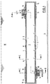
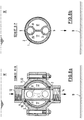
- a support body 1 designed as a distributor pipe for a partially perforated elastic membrane 2 surrounding it, which tightly encloses the support body 1 in the non-operating state, so that no liquid can penetrate into the gas space 3 enclosed by the support body 1, and which in the operating state, that is to say when gas is applied, lifts off the support body 1 in some areas in order to allow the gas to escape through its perforation into the liquid W.
- the support body 1 is closed at its ends with caps 15. Instead, the support body 1 can be extended at both ends by a number of sections via corresponding coupling elements in order to be adapted to the dimensions of the corresponding waste water basin.
- a number of such elongated tubular support bodies 1 can be distributed at intervals, for example parallel to one another, but also in different planes transverse to one another in such a wastewater basin be arranged to achieve a uniform fumigation.
- the support body 1 has near its one end in its cylindrical jacket a gas supply opening 4, the membrane 2 being cut out accordingly in order to contain the fumigation gas, in the given case air, e.g. to be able to feed from a connected supply hose via a supply nozzle 12.
- the feed connector 12 is held on the support body 1 by means of a clamp 11, the clamp 11 being sealed against the membrane 2 in the peripheral region of the feed channel of the feed connector 12 by means of an annular seal 18.
- the gas supply opening 4 is arranged at the top of the gas space 3 in this exemplary embodiment (the gas can also be supplied at the front or from below, for example, with appropriate connections), the gas space 3 and the region of the opposite end of the support tube 2 are located at the bottom the jacket of the support body 1 a condensate outlet opening 7; the latter opens into a drain pipe 14, which is held on the support body 1 with a clamp 13 and in the drain pipe connected thereto a e.g. controllable valve is provided, which is closed during gassing operation.
- the clamp 13 is sealed in the circumferential area of the drain channel of the drain connector 14 by means of an annular seal 19 against the membrane 2, which here has a corresponding recess for the condensate K to pass through.
- the membrane 2 is held on the support body 1 by means of a plurality of flexible sleeves 10 distributed over the length of the support body 1, while holding clamps 10 'are essentially fixedly arranged at the two ends of the support body 1.
- the cuffs 10 in between can be adjusted in their axial position as required to change the bubble pattern of the gassing device.
- the support tube 1 also has various gas outlet openings 5 distributed over its length at the lowest point of the gas space 3, whereby, as can be seen in particular from FIG. 1b, the membrane 2 in the region of the gas outlet openings 5 has non-perforated regions 16 so that the liquid W to be gassed in a lack of gas admission cannot enter gas space 3.
- the membrane 2 also has non-perforated areas 16 in the area of the condensate inlet opening 6, so that the liquid W to be gassed cannot enter the gas space 3 via the perforation of the membrane 2 and the condensate inlet opening 6 if there is no gassing operation.
- the condensate K that accumulates in the intermediate space between the jacket of the support body 1 and the membrane 2 during the gassing operation can reach the gas space 3 via the condensate inlet opening 6 and, as can be seen for example in FIG. 1a, accumulate at the bottom of the gas space 3.
- the accumulated condensate K can then be drained from the gas space 3, possibly with the aid of the pressure of the fumigation gas supplied via the gas supply opening 4 and after opening a discharge line (not shown) connected to the discharge nozzle 14. It is possible, for example, to raise the drain line up to above the water level and to spread the condensate by means of the gassing gas, such as air, after opening the drain valve.
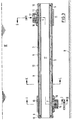
- a flood space limiting tube 8 with a closed wall is provided in the support body 1 and coaxially therewith, which is sealed at its ends by means of seals 9 against the inner peripheral surface of the support body 1, so that the thus annular gas space 3 is closed at its ends.
- the flood space delimitation tube 8 is open at its ends, so that the liquid W to be gassed can easily enter the inner flood space 17 and fill it.
- the flood space limiting tube 8 can have different lengths than the support tube 1, so that the gas space 3 can be adapted to different conditions relative to the inner and outer flood spaces 17, 17 '.
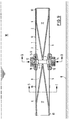
- the embodiment of the gassing device according to FIG. 2 also differs from that shown in FIG. 1 in that both the gas supply opening 4 with associated supply nozzle 12 and the condensate outlet opening 7 with associated outlet connector 14 are provided in the center of the support body 1 and from a common one Clamps 11, 13 are held. It is also possible here to adapt the length of the support body 1 including the flood space limiting tube 8 to the dimensions of the sewage basin to be acted upon, or to string together a plurality of similar support bodies 1 and flood space limitation tubes 8 and to couple them to one another.
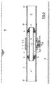
- FIG. 3 The embodiment of a gassing device according to the invention shown in Fig. 3 corresponds essentially to that of Fig. 1, with the difference that in the support body 1 a at its ends with respect to the inner circumferential surface of the support body 1 by means of seals 9 sealed flood chamber 8 is provided, which is in this Case extends over the entire length of the support tube 1.
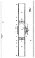
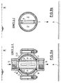
- FIG. 4 illustrates a cross section of another gassing device in the region of the condensate outlet opening 7 of the support body 1, a flexible drain valve 20 being screwed into the drain port 14.
- the flexible drain valve 20 is designed such that it opens when a predetermined pressure is exceeded and closes again when the pressure falls below a predetermined pressure.
- the condensate K accumulating at the bottom of the gas space 3 can be drained periodically, possibly with the participation of the gas pressure.
- the flood space limiting tube 8 is provided at its ends with an external thread, so that the length of the annular gas space 3 can be changed relative to the inner and outer flood spaces 17, 17 'by adjusting threaded washers 23 rotatable thereon.
- the gas supply opening 4 and the condensate outlet opening 7 are also merged on the underside of the support body 1 and, accordingly, the supply connection 12 and the outlet connection 14 as well as the two clamps 11, 13.
- the connections 12, 14 are connected, provided with the necessary valves, the supply line for the gassing gas and the discharge line for the condensate, so that the supporting body 1 can be supplied alternately with gassing gas and condensate can be drained or sucked out of it.
- the flood space limiting tube 8 of FIG. 5 is replaced by a threaded rod 21 arranged coaxially in the support tube 1, on which the ring-shaped seals 9 can be adjusted axially with the aid of nuts and lock nuts 24 and support disks 25 in order to achieve the Length of the gas space 3, which in this case is up to the threaded rod 21, makes up the entire cross section of the central part of the support body 21.
- FIG. 7 is again simplified compared to the embodiment of FIG. 6 in that the middle gas space 3 is sealed off from the outer flood spaces 17 'with the aid of axially adjustable rubber plugs 9' which fill the entire inner cross section of the support tube 1.
- the axial adjustment can be accomplished, for example, in that an actuating rod with a threaded end is screwed into outer axial threaded bores 22, by means of which the rubber plugs 9 'can be displaced.
- a channel-shaped gas space 3 and a channel-shaped condensate collection space 26 run inside the support tube 1, which by means of the flood space limiting tube 8 enclosing these and connected to one another via a web, extend from the flood spaces 17 extending over the entire length of the support body 1 are separated.
- the channel-shaped gas space 3 and the channel-shaped condensate collection space 26 are closed at their ends by means of stopper-shaped seals 9 '.
- the condensate inlet openings 6 can have a smaller cross section than the gas outlet openings 5.
- the flood space limiting tube 8 is designed in such a way that the channel-shaped gas space 3 and the k-shaped condensate collection space 26 taper from the center outwards so that they do not have to be closed separately at their ends.
Landscapes
- Life Sciences & Earth Sciences (AREA)
- Chemical & Material Sciences (AREA)
- Engineering & Computer Science (AREA)
- Biodiversity & Conservation Biology (AREA)
- Microbiology (AREA)
- Hydrology & Water Resources (AREA)
- Chemical Kinetics & Catalysis (AREA)
- Environmental & Geological Engineering (AREA)
- Water Supply & Treatment (AREA)
- Organic Chemistry (AREA)
- Separation Using Semi-Permeable Membranes (AREA)
- Seal Device For Vehicle (AREA)
- Liquid Crystal (AREA)
Applications Claiming Priority (2)
| Application Number | Priority Date | Filing Date | Title |
|---|---|---|---|
| DE29607577U DE29607577U1 (de) | 1996-04-26 | 1996-04-26 | Belüftungsvorrichtung |
| DE29607577U | 1996-04-26 |
Publications (2)
| Publication Number | Publication Date |
|---|---|
| EP0803475A1 true EP0803475A1 (fr) | 1997-10-29 |
| EP0803475B1 EP0803475B1 (fr) | 2002-12-11 |
Family
ID=8023165
Family Applications (1)
| Application Number | Title | Priority Date | Filing Date |
|---|---|---|---|
| EP97103338A Expired - Lifetime EP0803475B1 (fr) | 1996-04-26 | 1997-02-28 | Aérateur |
Country Status (2)
| Country | Link |
|---|---|
| EP (1) | EP0803475B1 (fr) |
| DE (2) | DE29607577U1 (fr) |
Cited By (2)
| Publication number | Priority date | Publication date | Assignee | Title |
|---|---|---|---|---|
| CN104768635A (zh) * | 2012-10-31 | 2015-07-08 | 埃克斯勒姆水处理美国股份有限公司 | 气体分配组件 |
| WO2021089355A1 (fr) * | 2019-11-08 | 2021-05-14 | Global Life Sciences Solutions Usa Llc | Dispositif d'aspersion pour un système de biotraitement et procédé de fabrication d'un dispositif d'aspersion |
Citations (3)
| Publication number | Priority date | Publication date | Assignee | Title |
|---|---|---|---|---|
| US3880965A (en) * | 1972-11-24 | 1975-04-29 | Charles G Dudis | Apparatus for aerating a liquid |
| US5059358A (en) * | 1990-06-04 | 1991-10-22 | Environmental Dynamics, Inc. | Tubular diffuser with adjustable plug |
| EP0482332A1 (fr) * | 1990-10-24 | 1992-04-29 | Schreiber, Berthold, Dipl.-Ing | Procédé pour injecter de l'air comprimé dans un liquide |
-
1996
- 1996-04-26 DE DE29607577U patent/DE29607577U1/de not_active Expired - Lifetime
-
1997
- 1997-02-28 DE DE59708918T patent/DE59708918D1/de not_active Expired - Lifetime
- 1997-02-28 EP EP97103338A patent/EP0803475B1/fr not_active Expired - Lifetime
Patent Citations (3)
| Publication number | Priority date | Publication date | Assignee | Title |
|---|---|---|---|---|
| US3880965A (en) * | 1972-11-24 | 1975-04-29 | Charles G Dudis | Apparatus for aerating a liquid |
| US5059358A (en) * | 1990-06-04 | 1991-10-22 | Environmental Dynamics, Inc. | Tubular diffuser with adjustable plug |
| EP0482332A1 (fr) * | 1990-10-24 | 1992-04-29 | Schreiber, Berthold, Dipl.-Ing | Procédé pour injecter de l'air comprimé dans un liquide |
Cited By (3)
| Publication number | Priority date | Publication date | Assignee | Title |
|---|---|---|---|---|
| CN104768635A (zh) * | 2012-10-31 | 2015-07-08 | 埃克斯勒姆水处理美国股份有限公司 | 气体分配组件 |
| WO2021089355A1 (fr) * | 2019-11-08 | 2021-05-14 | Global Life Sciences Solutions Usa Llc | Dispositif d'aspersion pour un système de biotraitement et procédé de fabrication d'un dispositif d'aspersion |
| US12324895B2 (en) | 2019-11-08 | 2025-06-10 | Global Life Sciences Solutions Usa Llc | Sparger device for a bioprocessing system and method of manufacturing a sparger device |
Also Published As
| Publication number | Publication date |
|---|---|
| DE29607577U1 (de) | 1996-07-11 |
| DE59708918D1 (de) | 2003-01-23 |
| EP0803475B1 (fr) | 2002-12-11 |
Similar Documents
| Publication | Publication Date | Title |
|---|---|---|
| DE112004000637T5 (de) | Vorrichtung zum Reinigen eines Gases | |
| DE2431516B2 (de) | Vorrichtung zur Abgabe von Fluiden | |
| EP0546335B1 (fr) | Dispositif pour introduire du gaz dans des fluides | |
| DE2205612A1 (de) | Vorrichtung und Anlage zum Behandeln von Flüssigkeiten, insbesondere Trinkwasser oder Abwasser | |
| WO1990011811A1 (fr) | Dispositif pour expulser des impuretes volatiles de la nappe souterraine | |
| EP4056292B1 (fr) | Agencement de filtres multiples | |
| EP2098487B1 (fr) | Dispositif de curage biologique | |
| EP0803475A1 (fr) | Aérateur | |
| DE4223942A1 (de) | Schlauchbelüfter | |
| DE3537906A1 (de) | Zyklon-abscheider | |
| DE202020104407U1 (de) | Filteranordnung | |
| EP1129768B1 (fr) | Dispositif d'aération | |
| DE2322511A1 (de) | Verfahren zum betrieb einer abwasserreinigungs- und schlammaufbereitungsanlage und anlage zur durchfuehrung des verfahrens | |
| DE2836113A1 (de) | Spritzsystem fuer verteilung von fluessigkeit, insbesondere fuer biofilterbetten, kuehltuerme u.dgl. | |
| EP1493717A1 (fr) | Procédé de lavage d'un réacteur de traitement biologique d'eaux usées | |
| DE3321038C2 (fr) | ||
| DE2836244A1 (de) | Ventil | |
| DE2635923C3 (de) | Muffenventil | |
| EP0421920A1 (fr) | Tube de drainage pour filtre à tube de drainage se lavant à contre courant | |
| AT411249B (de) | Klär- oder absetzbecken | |
| EP0789611A1 (fr) | Dispositif a filtres en forme de bougie utilise pour la filtration de biere | |
| WO1994026672A1 (fr) | Aerateur se presentant sous forme de flexible | |
| DE7421406U (de) | Filtervorrichtung | |
| DE1156712B (de) | Tropfkoerper zur biologischen Reinigung von Abwasser | |
| WO2010086423A1 (fr) | Aérateur |
Legal Events
| Date | Code | Title | Description |
|---|---|---|---|
| PUAI | Public reference made under article 153(3) epc to a published international application that has entered the european phase |
Free format text: ORIGINAL CODE: 0009012 |
|
| AK | Designated contracting states |
Kind code of ref document: A1 Designated state(s): CH DE IT LI NL SE |
|
| 17P | Request for examination filed |
Effective date: 19980423 |
|
| 17Q | First examination report despatched |
Effective date: 20000114 |
|
| GRAG | Despatch of communication of intention to grant |
Free format text: ORIGINAL CODE: EPIDOS AGRA |
|
| GRAG | Despatch of communication of intention to grant |
Free format text: ORIGINAL CODE: EPIDOS AGRA |
|
| GRAH | Despatch of communication of intention to grant a patent |
Free format text: ORIGINAL CODE: EPIDOS IGRA |
|
| GRAH | Despatch of communication of intention to grant a patent |
Free format text: ORIGINAL CODE: EPIDOS IGRA |
|
| GRAA | (expected) grant |
Free format text: ORIGINAL CODE: 0009210 |
|
| AK | Designated contracting states |
Kind code of ref document: B1 Designated state(s): CH DE IT LI NL SE |
|
| REG | Reference to a national code |
Ref country code: CH Ref legal event code: EP |
|
| REF | Corresponds to: |
Ref document number: 59708918 Country of ref document: DE Date of ref document: 20030123 |
|
| REG | Reference to a national code |
Ref country code: CH Ref legal event code: NV Representative=s name: ISLER & PEDRAZZINI AG |
|
| PLBE | No opposition filed within time limit |
Free format text: ORIGINAL CODE: 0009261 |
|
| STAA | Information on the status of an ep patent application or granted ep patent |
Free format text: STATUS: NO OPPOSITION FILED WITHIN TIME LIMIT |
|
| 26N | No opposition filed |
Effective date: 20030912 |
|
| REG | Reference to a national code |
Ref country code: CH Ref legal event code: PCAR Free format text: ISLER & PEDRAZZINI AG;POSTFACH 1772;8027 ZUERICH (CH) |
|
| PGFP | Annual fee paid to national office [announced via postgrant information from national office to epo] |
Ref country code: NL Payment date: 20090223 Year of fee payment: 13 |
|
| PGFP | Annual fee paid to national office [announced via postgrant information from national office to epo] |
Ref country code: IT Payment date: 20090225 Year of fee payment: 13 |
|
| PGFP | Annual fee paid to national office [announced via postgrant information from national office to epo] |
Ref country code: DE Payment date: 20100427 Year of fee payment: 14 |
|
| REG | Reference to a national code |
Ref country code: NL Ref legal event code: V1 Effective date: 20100901 |
|
| PG25 | Lapsed in a contracting state [announced via postgrant information from national office to epo] |
Ref country code: NL Free format text: LAPSE BECAUSE OF NON-PAYMENT OF DUE FEES Effective date: 20100901 |
|
| PG25 | Lapsed in a contracting state [announced via postgrant information from national office to epo] |
Ref country code: IT Free format text: LAPSE BECAUSE OF NON-PAYMENT OF DUE FEES Effective date: 20100228 |
|
| PGFP | Annual fee paid to national office [announced via postgrant information from national office to epo] |
Ref country code: SE Payment date: 20110221 Year of fee payment: 15 Ref country code: CH Payment date: 20110222 Year of fee payment: 15 |
|
| REG | Reference to a national code |
Ref country code: DE Ref legal event code: R119 Ref document number: 59708918 Country of ref document: DE Effective date: 20110901 |
|
| REG | Reference to a national code |
Ref country code: CH Ref legal event code: PL |
|
| REG | Reference to a national code |
Ref country code: SE Ref legal event code: EUG |
|
| PG25 | Lapsed in a contracting state [announced via postgrant information from national office to epo] |
Ref country code: SE Free format text: LAPSE BECAUSE OF NON-PAYMENT OF DUE FEES Effective date: 20120301 Ref country code: CH Free format text: LAPSE BECAUSE OF NON-PAYMENT OF DUE FEES Effective date: 20120229 Ref country code: LI Free format text: LAPSE BECAUSE OF NON-PAYMENT OF DUE FEES Effective date: 20120229 |
|
| PG25 | Lapsed in a contracting state [announced via postgrant information from national office to epo] |
Ref country code: DE Free format text: LAPSE BECAUSE OF NON-PAYMENT OF DUE FEES Effective date: 20110901 |