EP0803596A2 - Méthode de régulation déterminant une valeur minimale dans une machine d'étirage ou de cardage - Google Patents
Méthode de régulation déterminant une valeur minimale dans une machine d'étirage ou de cardage Download PDFInfo
- Publication number
- EP0803596A2 EP0803596A2 EP97101944A EP97101944A EP0803596A2 EP 0803596 A2 EP0803596 A2 EP 0803596A2 EP 97101944 A EP97101944 A EP 97101944A EP 97101944 A EP97101944 A EP 97101944A EP 0803596 A2 EP0803596 A2 EP 0803596A2
- Authority
- EP
- European Patent Office
- Prior art keywords
- control
- value
- card
- sliver
- quality
- Prior art date
- Legal status (The legal status is an assumption and is not a legal conclusion. Google has not performed a legal analysis and makes no representation as to the accuracy of the status listed.)
- Granted
Links
Images
Classifications
-
- D—TEXTILES; PAPER
- D01—NATURAL OR MAN-MADE THREADS OR FIBRES; SPINNING
- D01H—SPINNING OR TWISTING
- D01H5/00—Drafting machines or arrangements ; Threading of roving into drafting machine
- D01H5/18—Drafting machines or arrangements without fallers or like pinned bars
- D01H5/32—Regulating or varying draft
- D01H5/38—Regulating or varying draft in response to irregularities in material ; Measuring irregularities
- D01H5/42—Regulating or varying draft in response to irregularities in material ; Measuring irregularities employing electrical time-delay devices
Definitions
- the technical field of the invention is the setting of a regulating section in the textile industry, which has the task of stretching strips of textile fiber (non-woven fabric) several times and to bring about an equalization by the stretching.
- a regulating path is described in EP 176 661 B1 , distinguishing between a short-staple spinning mill and a long-staple spinning mill, the regulating path being described as working according to the principle of the open control loop (pre-control) in the context of the long-staple spinning mill.
- the electronic control system RSB 851 from Rieter Ingolstadt AG which has been accessible to the public since August 1990, also works according to the principle of pre-control, in which the strength of the incoming fiber slivers (total sliver made up of several individual slivers) is mechanically scanned (groove roller) at the entrance to the machine / Feeler roller) is continuously measured and converted into electrical signals.
- the measured values are fed to an electronic memory with a variable delay.
- the delay in the measured value means that the corresponding sliver thickness in the sliver can run through the distance between the pair of input feeler rollers and the place of delay.
- control point is useful.
- this type of setting eliminates the time-consuming tape test, this type of setting also causes a continuous undesired control movement with regard to the parameters of the pilot control (the electronic regulating system). This constant control movement causes unrest in the control.
- Machine-internal error influences e.g. defective rollers, slippage of the rollers, play in the gear, etc.
- the object of the invention is therefore to bring about the acceleration of the optimization as described in the publication mentioned at the outset, but not to design the optimization in such a way that it creates an inherent unrest in the route regulation.
- the starting point and knowledge of the invention is to leave the on-line adaptation of the parameters of the regulation and to proceed to determine the parameters of the regulation in a pre-operational test or setting on the line or card and to leave it largely unchanged during operation ( Claim 1).
- a pre-operational set-up a plurality of measured values are determined which represent a quantity which characterizes the quality, relating to the drawn fiber sliver.
- a function course is determined, the minimum of which corresponds to the value which promises the best adaptation of the regulation to the current sliver.
- the multiple measured values that are recorded and with which the function curve is determined are measured at a different setting of the regulation, so that an incrementally changing parameter, e.g., for the definition of the function curve to be evaluated. the starting point of the rule of "electronic memory", with each of its increment values is to be assigned to one of the measured values.
- the most favorable value of a parameter can be determined in the pre-operational test run according to the invention.
- this value is taken over into the regulation either directly or after going through a plausibility check or else after suggestions to a user and upon his confirmation in order to keep a value that is constant over the long term.
- this avoids constantly changing the setting values once found to be good for the regulation and thereby running the risk of making changes due to disturbance variables that are not specific to the sliver per se.
- the CV value which characterizes an amplitude evaluation of the fiber sliver thickness in the selective length range of the fiber sliver supplied, can be used as a quality-characterizing variable.
- a microprocessor can be used to determine this CV value for a specific tape length and to record it as a quality-identifying measurement value for one of the incrementally changing parameters (claim 8) before the minimum value search is carried out.
- the one and the other parameters can be optimized in succession (claim 2, claim 3); the non-optimized parameter in each case advantageously does not change its value during the measurement value recording for the minimum value function.
- the distance between the measured values for the quality-defining quantity can be reduced (claim 11). This improves the recognizability of the minimum, since an excessively good quality of the incoming fiber sliver shows an only weakly pronounced minimum of the CV measured values above the respective incrementally adjusted regulation parameter. If the minimum becomes too flat, a differentiation or an approximate method can also be used for the evaluation.
- the equidistant values for the control starting point are advantageously based on the distance between the pair of input rollers and the delay point; they will therefore be standardized in a unit of length.
- the proposals according to the invention work faster and at the same time more precisely, avoiding that non-fiber-band-specific influences have an influence on the adaptation of the regulation.
- the minimum value search is a piece of work that can be easily performed algorithmically by a computer.
- a user is proposed one or more values for setting the regulation, which the user can then use or reject.
- a major advantage of measuring the strip before it is deposited is that errors caused by the deposit no longer have any influence on the optimization, as was the case when a CV value was determined in the textile laboratory or when the "strip test" was the case , in which the stretched sliver was removed after the sliver had been deposited in the can and was broken down in sections into sorts of different sliver lengths in order to obtain information about the quality of the adjustment of the regulation via the respective weight.
- only one pointer position is used as a write-out point (read) and write-in point (write) on a memory.
- the start and end of the measured value memory are marked by two limit values, which can also be designed as pointers, but which are not incremented over time, but only change their values if the control starting point of the precontrol is to be changed.
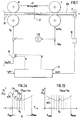
- the aim of the control and regulation is to know the warping point 21 in the warping field VF, in which there is a strong fiber warping of the incoming sliver 20, as precisely as possible and to ensure that it is from a thickness measurement signal d 0 (n), that comes from a pair of input rollers, which is upstream of the center rollers M and possibly these upstream inlet rollers, is influenced via a channel or pilot control 10 in such a way that a change in distortion occurs by changing the speed of the center rollers M precisely when a changed thickness d 0 , which was previously measured, is in the delay point 21.
- the sliver 20 is composed of several individual strands, which are brought together in front of the input feeler rollers, not shown here, and whose thickness is determined together.
- the thickness of the band 20 changes, the warping in the warping field VF must change accordingly, which is achieved via a pilot control 10.
- the speed v 0 of the center rolls M is changed while the speed of the delivery rolls L remains constant, which in the example shown here has about six times the delivery speed when six fiber slivers are brought together to form a strand 20 at the entrance.
- a corresponding channel for the speed v 0 over 1/6 of the stationary speed 6 ⁇ v 0 of the delivery rollers L can also be integrated in the pilot control 10.
- the mechanical part ends behind the delivery rolls L with calender rolls F for drawing off the drawn fiber sliver 20a.
- a jug can serve as a shelf.
- a measurement is made on the drawn fiber sliver behind the exit of the delivery rollers L and before the deposit. In the example shown here, this measurement relates to the pair of calender rolls with which the quality of the sliver 20a can be measured after stretching. It is suitable as a quality-defining quantity of the CV% value, which can be measured directly during the transport of the sliver (see publication by Rieter Link, issue 2/95, pages 14 and 15).
- the samples (measured values) present in discrete length samples are provided as a CV value by calculation over a defined length.
- the CV value forms an evaluation variable of a system control 11.
- the controller 11 receives an optimization command "OPT" and uses it to generate commands for incrementing the control starting point R and gain K.
- sliver 20 is stretched between center rolls M and delivery rolls L and conveyed into a can by a depositing device. Separate measurements or examinations of the deposited tape 20a do not need to take place, however, since the CV value measurement is provided with the measuring device 12.
- the control sets an arbitrary, usually a suspected, first value R min , previously determined from empirical values (eg table), for the control starting point in a channel of the pilot control 10.
- the empirical value from the material table can be entered using a keyboard.
- a knowledge memory integrated in the control 11 can also provide the empirical value from a stored table on demand.
- CV 1 a CV value is recorded, which is designated CV 1 in FIG. 2a .
- This measured value from the measuring device 12 is written into a memory area of the controller 11.
- the control point R of the pilot control 10 set first is then changed by at least one increment. Again, the tape 20 will run for a certain time until the corresponding CV 2 value is stored by the controller 11 in the same memory area.
- control starting point is incremented further and a CV 3 value is measured again until a reasonable number (approx. 5, 10 or 15 measured values) is available, oriented between a minimum control starting point R min and a maximum control starting point R max .
- the function a (R) thus formed in the memory area of the controller 11 can be examined to a minimum by evaluation methods, which can be assumed at R 0 in the case of the function shown in FIG. 2a, where the minimum CV min is.
- the position recognized as the minimum CV min of the function a also denoted by a m , defines the best setting for the control starting point R of the pilot control 10, with the gain factor K initially kept constant in the channel for the thickness measurement signal d 0 (n).
- this control point of use can be transferred to the electronic memory of the pilot control 10, if necessary after having passed a plausibility check and confirmed by the operator.
- n where n should be between 5 and 10, does not lead to a usable result for K 0 as the best value for the gain and R 0 as the best value for the control starting point, one or the other curve can also be differentiated from the program control in the controller 11 to make the minimum clearer.
- the differentiation means that it is not a minimum but a zero crossing of the differentiated function that must be determined, which is possible with the measurement functions a (R) and b (K) running to a certain extent.
- R 0 and K 0 are adopted directly in the pilot control 10 before the actual production operation of the line is started.
- the determined values for R and K can, however, also first be proposed to the operator who, if explicitly requested, accepts them in the pilot control 10 by actuating an input element (key).
- a plausibility check can be provided, which uses a predefined admissibility window between two limit values for a certain quality of sliver 20 in order to obtain the best value determined by the minimum search then check whether it is in this window.
- the parameters for the control point of operation and for the amplification of the pilot control 10 set for the production operation are no longer changed during the production operation, but rather remain constant. At large time intervals or if it is suspected that these parameters are no longer the best setting for the route, a new minimum value search can be carried out in a setting on the route, for which the production will be briefly interrupted.
- the control point R can be set corresponds to the distance or distance that a piece of tape needs from the measuring point to the delay point. If the optimization is immediately based on distances, the changes in the control point of application can be 3 mm, between two measured values CV 1 and CV 2 . The distances to the other measured values can also be the same in order to obtain a path-constant scanning. Only when the CV value has been measured with a sufficiently large number of individual measurements is a secure value available for storage as a quality measurement of the functions a (R) and b (K).
- the quality functions a (R) and b (K) can be determined continuously in the setting run without stopping and adjusting the belt.
- the process is extremely fast, user-friendly and very quiet in terms of control technology for the actual production operation with the best possible parameters.
- the hardware or software implementation in the controller 11 for changing the control starting point R of the pilot control 10 is implemented with a variable memory length. Measured values that originate from the thickness measurement d 0 (n), the instantaneous values of the current values, are continuously written into these memory cells arranged in the memory represent the strip thickness running through the pair of input rollers.
- the memory in which the length-discrete measured values mentioned are stored has a changing length or - shown in a circle - an expanding and reducing extent if one assumes the same distance between the stored values on the circumference of the circle.
- the measured values are stored in the memory by specifying a pointer value (pointer) and read out at the same location.
- pointer pointer
- the delay between two read-write cycles for a memory cell corresponds to the path from the measuring point to the point of warp between the center rollers and the delivery rollers (standard starting point). The start and end of the memory are therefore in the same place.
- the old value is read first, which now specifies the thickness that is in the delay point, and then the new value is stored as the thickness value that has just been measured via the pair of tas rolls with the time-discrete value d 0 (n).
- the old value corresponds to the previous cycle, the new value is that of the current cycle.
- the memory length does not change continuously. There are also no need for two pointers, one of which defines the place of writing and the other of which defines the place of reading.
Landscapes
- Engineering & Computer Science (AREA)
- Mechanical Engineering (AREA)
- Textile Engineering (AREA)
- Spinning Or Twisting Of Yarns (AREA)
- Preliminary Treatment Of Fibers (AREA)
Applications Claiming Priority (2)
| Application Number | Priority Date | Filing Date | Title |
|---|---|---|---|
| DE19615947A DE19615947B4 (de) | 1996-04-22 | 1996-04-22 | Minimalwert-suchende Regulierungsoptimierung |
| DE19615947 | 1996-04-22 |
Publications (3)
| Publication Number | Publication Date |
|---|---|
| EP0803596A2 true EP0803596A2 (fr) | 1997-10-29 |
| EP0803596A3 EP0803596A3 (fr) | 1999-07-14 |
| EP0803596B1 EP0803596B1 (fr) | 2001-07-04 |
Family
ID=7792050
Family Applications (1)
| Application Number | Title | Priority Date | Filing Date |
|---|---|---|---|
| EP97101944A Expired - Lifetime EP0803596B1 (fr) | 1996-04-22 | 1997-02-07 | Méthode de régulation déterminant une valeur minimale dans une machine d'étirage ou de cardage |
Country Status (3)
| Country | Link |
|---|---|
| US (1) | US5771542A (fr) |
| EP (1) | EP0803596B1 (fr) |
| DE (2) | DE19615947B4 (fr) |
Cited By (2)
| Publication number | Priority date | Publication date | Assignee | Title |
|---|---|---|---|---|
| EP1350870A3 (fr) * | 2002-04-02 | 2004-01-28 | Rieter Ingolstadt Spinnereimaschinenbau AG | Appareil et procédé pour optimaliser des valeurs de réglage d'une machine de filature |
| EP1078116B2 (fr) † | 1998-05-13 | 2006-07-12 | Maschinenfabrik Rieter Ag | Machine traitant une matiere textile et dotee d'un bac d'etirage |
Families Citing this family (14)
| Publication number | Priority date | Publication date | Assignee | Title |
|---|---|---|---|---|
| WO1999011847A1 (fr) * | 1997-09-01 | 1999-03-11 | Maschinenfabrik Rieter Ag | Banc d'etirage regule |
| DE59903261D1 (de) * | 1998-06-12 | 2002-12-05 | Rieter Ag Maschf | Regulierstreckwerk |
| DE19921429B4 (de) * | 1998-06-29 | 2017-03-02 | Rieter Ingolstadt Gmbh | Verfahren und Vorrichtung zur Fehlerkorrektur eines von einem Meßorgan gelieferten Meßwertes von Faserband in einer Textilmaschine |
| DE10041893A1 (de) | 2000-08-25 | 2002-03-07 | Truetzschler Gmbh & Co Kg | Vorrichtung an einer Regulierstrecke zum direkten Ermitteln von Einstellwerten für den Reguliereinsatzpunkt |
| DE10041894B4 (de) * | 2000-08-25 | 2011-08-11 | Trützschler GmbH & Co. KG, 41199 | Verfahren und Vorrichtung zum Verstrecken von Faserband in einer Regulierstrecke für Fasermaterial zum direkten Ermitteln von Einstellwerten für den Reguliereinsatzpunkt |
| DE10041892A1 (de) * | 2000-08-25 | 2002-03-07 | Truetzschler Gmbh & Co Kg | Vorrichtung an einer Regulierstrecke für Faserbänder zum direkten Ermitteln von Einstellwerten für den Reguliereinsatzpunkt |
| DE10059262A1 (de) | 2000-11-29 | 2002-06-13 | Truetzschler Gmbh & Co Kg | Verfahren zur Optimierung der Regelung und Steuerung von Verzugseinrichtungen an Spinnereimaschinen |
| US6543092B2 (en) * | 2001-02-16 | 2003-04-08 | TRüTZSCHLER GMBH & CO. KG | Method of determining setting values for a preliminary draft in a regulated draw frame |
| DE10236778B4 (de) * | 2002-08-10 | 2011-05-05 | Rieter Ingolstadt Gmbh | Verfahren und Vorrichtung zum Verstrecken von mindestens eines Faserband |
| DE10253197B4 (de) * | 2002-11-15 | 2011-05-05 | Rieter Ingolstadt Gmbh | Verfahren zum Bestimmen des Regeleinsatzpunktes bei Spinnereivorbereitungsmaschinen sowie Spinnereivorbereitungsmaschine |
| BRPI0610234B1 (pt) * | 2005-05-06 | 2016-08-16 | Sree Ayyanar Spinning And Weaving Mills Ltd | método para regularizar o estiramento de uma mistura de fibras e sistema de estiramento para fibras |
| DE102005037124A1 (de) * | 2005-08-06 | 2007-02-08 | Rieter Ingolstadt Spinnereimaschinenbau Ag | Verfahren zur Steuerung des Verzugs eines Verzugsfeldes einer Textilmaschine sowie Textilmaschine |
| DE102006029639B4 (de) * | 2006-06-28 | 2018-04-12 | Rieter Ingolstadt Gmbh | Verfahren zur Steuerung des Verzugs eines Streckwerks einer Textilmaschine sowie Textilmaschine |
| CN114351301B (zh) * | 2021-12-17 | 2023-02-28 | 东华大学 | 一种基于牵伸区内纤维运动状态稳定的自调匀整方法 |
Family Cites Families (11)
| Publication number | Priority date | Publication date | Assignee | Title |
|---|---|---|---|---|
| DE3429718A1 (de) * | 1984-08-13 | 1986-02-20 | H. Dipl.-Ing. 3400 Göttingen Lobenhoffer | Verfahren zur herstellung von werkstoffkoerpern |
| CH668781A5 (de) * | 1984-09-25 | 1989-01-31 | Zellweger Uster Ag | Verfahren und vorrichtung zur optimierung des streckprozesses bei regulierstrecken der textilindustrie. |
| IT1227771B (it) * | 1986-07-04 | 1991-05-06 | Zinser Textilmaschinen Gmbh | Procedimento e dispositivo per regolare lo stiro di un nastro di fibre in una macchina tessile. |
| JPH0765250B2 (ja) * | 1987-01-09 | 1995-07-12 | 中部精工株式会社 | 練条機 |
| WO1992022692A2 (fr) * | 1991-06-04 | 1992-12-23 | Schubert & Salzer Maschinenfabrik Ag | Procede et dispositif de correction du moment et de l'intensite de regulation |
| DE4215682B4 (de) * | 1991-06-04 | 2004-07-22 | Rieter Ingolstadt Spinnereimaschinenbau Ag | Verfahren und Vorrichtung zur Korrektur des Reguliereinsatzpunktes und der Regulierintensität |
| DE4131765A1 (de) * | 1991-09-24 | 1993-03-25 | Siemens Ag | Regelparameter-verbesserungsverfahren fuer industrielle anlagen |
| DE4219777A1 (de) * | 1992-06-17 | 1993-12-23 | Rieter Ingolstadt Spinnerei | Verfahren und Vorrichtung zur Signalanalyse einer Regulierstrecke |
| DE4306343C1 (de) * | 1993-02-25 | 1994-07-14 | Grosenhainer Textilmaschbau | Verfahren zur Vergleichmäßigung von textilen Faserbändern |
| DE9320794U1 (de) * | 1993-12-20 | 1995-02-16 | Trützschler GmbH & Co KG, 41199 Mönchengladbach | Regulierstreckwerk für Faserbänder an einer Strecke mit einem Einlaufmeßorgan |
| DE4434294C2 (de) * | 1994-09-19 | 1999-04-29 | Hartmann & Braun Gmbh & Co Kg | Verfahren zur Steuerung eines nichtlinearen, technischen Prozesses |
-
1996
- 1996-04-22 DE DE19615947A patent/DE19615947B4/de not_active Expired - Lifetime
-
1997
- 1997-02-07 EP EP97101944A patent/EP0803596B1/fr not_active Expired - Lifetime
- 1997-02-07 DE DE59703932T patent/DE59703932D1/de not_active Expired - Lifetime
- 1997-03-20 US US08/822,339 patent/US5771542A/en not_active Expired - Lifetime
Cited By (2)
| Publication number | Priority date | Publication date | Assignee | Title |
|---|---|---|---|---|
| EP1078116B2 (fr) † | 1998-05-13 | 2006-07-12 | Maschinenfabrik Rieter Ag | Machine traitant une matiere textile et dotee d'un bac d'etirage |
| EP1350870A3 (fr) * | 2002-04-02 | 2004-01-28 | Rieter Ingolstadt Spinnereimaschinenbau AG | Appareil et procédé pour optimaliser des valeurs de réglage d'une machine de filature |
Also Published As
| Publication number | Publication date |
|---|---|
| DE59703932D1 (de) | 2001-08-09 |
| DE19615947A1 (de) | 1997-10-23 |
| US5771542A (en) | 1998-06-30 |
| EP0803596A3 (fr) | 1999-07-14 |
| EP0803596B1 (fr) | 2001-07-04 |
| DE19615947B4 (de) | 2007-10-31 |
Similar Documents
| Publication | Publication Date | Title |
|---|---|---|
| DE19822886B4 (de) | Regulierstreckwerk für einen Faserverband, z. B. Baumwolle, Chemiefasern o. dgl. mit mindestens einem Verzugsfeld | |
| EP0803596B1 (fr) | Méthode de régulation déterminant une valeur minimale dans une machine d'étirage ou de cardage | |
| DE2409882C3 (de) | Vorrichtung zum Erkennen des fehlerhaften Arbeiten« von Spinnmaschinen | |
| DE10214955B4 (de) | Spinnereivorbereitungsmaschine | |
| WO2003050530A2 (fr) | Utilisation de micro-ondes dans l'industrie de la filature | |
| DE102007039067A1 (de) | Vorrichtung an einer Kämmmaschine zur Überwachung des Kämmlingsanteils | |
| DE3425345A1 (de) | Verfahren und vorrichtung zum erzeugen einer gleichmaessigen, kontinuierlichen fasermenge | |
| EP1350870B1 (fr) | Appareil et procédé pour optimaliser des valeurs de réglage d'une machine de filature | |
| LU503150B1 (de) | Verfahren zur computergestützten Anpassung einer Konfiguration für unterschiedliche textile Produktionen | |
| DE3427357C2 (de) | Offenend-Spinnmaschine mit einer fahrbaren Bedienungsvorrichtung | |
| EP2034059A2 (fr) | Procédé de détermination du poids lineaire d'un ruban de fibres et machine de préparation de filature | |
| DE10041894B4 (de) | Verfahren und Vorrichtung zum Verstrecken von Faserband in einer Regulierstrecke für Fasermaterial zum direkten Ermitteln von Einstellwerten für den Reguliereinsatzpunkt | |
| EP1211340A2 (fr) | Procédé et dispositif dans un métier à filer pour determiner le moment de régulation | |
| EP0291710B1 (fr) | Procédé et dispositif pour surveiller la partie rattachée du fil sur un métier à filer à bout libre | |
| CH696121A5 (de) | Vorrichtung an einem Streckwerk für Faserbänder, z.B. einer Strecke, zum Ermitteln von Einstellwerten für den Vorverzug. | |
| EP1675979A1 (fr) | Procede et dispositif de fabrication d'un fil fantaisie retordu | |
| CH695270A5 (de) | Vorrichtung an einer Regulierstrecke zum direkten Ermitteln von Einstellwerten fuer den Reguliereinsatzpunkt. | |
| DE102005019760B4 (de) | Spinnereimaschine mit einem Streckwerk zum Verstrecken eines Faserverbandes und entsprechendes Verfahren | |
| EP0678601A2 (fr) | Banc d'étirage contrôlé | |
| CH695296A5 (de) | Vorrichtung an einer Regulierstrecke fuer Faserbaender zum direkten Ermitteln von Einstellwerten fuer den Reguliereinsatzpunkt. | |
| CH686446A5 (de) | Verfahren und Vorrichtung zur On-line Qualitaetsueberwachung im Spinnereivorwerk. | |
| CH522051A (de) | Verfahren und Vorrichtung zur Überwachung und/oder Regelung der Speisung von Karden | |
| WO2022148637A1 (fr) | Procédé de détermination de la quantité de blousse sur une peigneuse et peigneuse | |
| DE102023116482A1 (de) | Verfahren zum Überprüfen der Gültigkeit eines Anzeigewertes während eines Kämmvorgangs und Kämmmaschine | |
| CH695618A5 (de) | Vorrichtung an einer Regulierstrecke zum Ermitteln von Einstellwerten für einen Vorverzug eines Faserbandes. |
Legal Events
| Date | Code | Title | Description |
|---|---|---|---|
| PUAI | Public reference made under article 153(3) epc to a published international application that has entered the european phase |
Free format text: ORIGINAL CODE: 0009012 |
|
| 17P | Request for examination filed |
Effective date: 19970207 |
|
| AK | Designated contracting states |
Kind code of ref document: A2 Designated state(s): CH DE IT LI |
|
| PUAL | Search report despatched |
Free format text: ORIGINAL CODE: 0009013 |
|
| AK | Designated contracting states |
Kind code of ref document: A3 Designated state(s): CH DE IT LI |
|
| 17Q | First examination report despatched |
Effective date: 19991104 |
|
| GRAG | Despatch of communication of intention to grant |
Free format text: ORIGINAL CODE: EPIDOS AGRA |
|
| GRAG | Despatch of communication of intention to grant |
Free format text: ORIGINAL CODE: EPIDOS AGRA |
|
| GRAH | Despatch of communication of intention to grant a patent |
Free format text: ORIGINAL CODE: EPIDOS IGRA |
|
| GRAH | Despatch of communication of intention to grant a patent |
Free format text: ORIGINAL CODE: EPIDOS IGRA |
|
| GRAA | (expected) grant |
Free format text: ORIGINAL CODE: 0009210 |
|
| AK | Designated contracting states |
Kind code of ref document: B1 Designated state(s): CH DE IT LI |
|
| ITF | It: translation for a ep patent filed | ||
| REG | Reference to a national code |
Ref country code: CH Ref legal event code: EP |
|
| REF | Corresponds to: |
Ref document number: 59703932 Country of ref document: DE Date of ref document: 20010809 |
|
| PLBE | No opposition filed within time limit |
Free format text: ORIGINAL CODE: 0009261 |
|
| STAA | Information on the status of an ep patent application or granted ep patent |
Free format text: STATUS: NO OPPOSITION FILED WITHIN TIME LIMIT |
|
| 26N | No opposition filed | ||
| PGFP | Annual fee paid to national office [announced via postgrant information from national office to epo] |
Ref country code: CH Payment date: 20150220 Year of fee payment: 19 Ref country code: DE Payment date: 20150224 Year of fee payment: 19 Ref country code: IT Payment date: 20150221 Year of fee payment: 19 |
|
| REG | Reference to a national code |
Ref country code: DE Ref legal event code: R119 Ref document number: 59703932 Country of ref document: DE |
|
| REG | Reference to a national code |
Ref country code: CH Ref legal event code: PL |
|
| PG25 | Lapsed in a contracting state [announced via postgrant information from national office to epo] |
Ref country code: LI Free format text: LAPSE BECAUSE OF NON-PAYMENT OF DUE FEES Effective date: 20160229 Ref country code: CH Free format text: LAPSE BECAUSE OF NON-PAYMENT OF DUE FEES Effective date: 20160229 |
|
| PG25 | Lapsed in a contracting state [announced via postgrant information from national office to epo] |
Ref country code: IT Free format text: LAPSE BECAUSE OF NON-PAYMENT OF DUE FEES Effective date: 20160207 |
|
| PG25 | Lapsed in a contracting state [announced via postgrant information from national office to epo] |
Ref country code: DE Free format text: LAPSE BECAUSE OF NON-PAYMENT OF DUE FEES Effective date: 20160901 |