EP0803676A1 - Raccord rapide pour tuyaux flexibles ou canalisations - Google Patents
Raccord rapide pour tuyaux flexibles ou canalisations Download PDFInfo
- Publication number
- EP0803676A1 EP0803676A1 EP96106347A EP96106347A EP0803676A1 EP 0803676 A1 EP0803676 A1 EP 0803676A1 EP 96106347 A EP96106347 A EP 96106347A EP 96106347 A EP96106347 A EP 96106347A EP 0803676 A1 EP0803676 A1 EP 0803676A1
- Authority
- EP
- European Patent Office
- Prior art keywords
- sleeve
- sleeve body
- adapter
- quick coupling
- coupling according
- Prior art date
- Legal status (The legal status is an assumption and is not a legal conclusion. Google has not performed a legal analysis and makes no representation as to the accuracy of the status listed.)
- Granted
Links
- 230000008878 coupling Effects 0.000 title claims abstract description 42
- 238000010168 coupling process Methods 0.000 title claims abstract description 42
- 238000005859 coupling reaction Methods 0.000 title claims abstract description 42
- 230000006835 compression Effects 0.000 claims abstract description 9
- 238000007906 compression Methods 0.000 claims abstract description 9
- 238000003780 insertion Methods 0.000 claims abstract description 5
- 230000037431 insertion Effects 0.000 claims abstract description 5
- 239000000463 material Substances 0.000 claims abstract 2
- 238000007789 sealing Methods 0.000 claims description 14
- 239000007788 liquid Substances 0.000 claims description 2
- 239000013013 elastic material Substances 0.000 claims 1
- 239000007789 gas Substances 0.000 claims 1
- 239000002184 metal Substances 0.000 description 12
- 238000003801 milling Methods 0.000 description 5
- 239000011324 bead Substances 0.000 description 4
- 238000002347 injection Methods 0.000 description 4
- 239000007924 injection Substances 0.000 description 4
- 239000002994 raw material Substances 0.000 description 3
- 238000011161 development Methods 0.000 description 2
- 230000018109 developmental process Effects 0.000 description 2
- 230000000694 effects Effects 0.000 description 2
- 238000005516 engineering process Methods 0.000 description 2
- 238000004519 manufacturing process Methods 0.000 description 2
- 239000000243 solution Substances 0.000 description 2
- 125000006850 spacer group Chemical group 0.000 description 2
- UDHXJZHVNHGCEC-UHFFFAOYSA-N Chlorophacinone Chemical compound C1=CC(Cl)=CC=C1C(C=1C=CC=CC=1)C(=O)C1C(=O)C2=CC=CC=C2C1=O UDHXJZHVNHGCEC-UHFFFAOYSA-N 0.000 description 1
- 229910000831 Steel Inorganic materials 0.000 description 1
- 238000003889 chemical engineering Methods 0.000 description 1
- 238000010276 construction Methods 0.000 description 1
- 238000002788 crimping Methods 0.000 description 1
- 230000007812 deficiency Effects 0.000 description 1
- 238000001746 injection moulding Methods 0.000 description 1
- 230000000149 penetrating effect Effects 0.000 description 1
- 230000035515 penetration Effects 0.000 description 1
- 239000010959 steel Substances 0.000 description 1
- 230000003313 weakening effect Effects 0.000 description 1
Images


Classifications
-
- F—MECHANICAL ENGINEERING; LIGHTING; HEATING; WEAPONS; BLASTING
- F16—ENGINEERING ELEMENTS AND UNITS; GENERAL MEASURES FOR PRODUCING AND MAINTAINING EFFECTIVE FUNCTIONING OF MACHINES OR INSTALLATIONS; THERMAL INSULATION IN GENERAL
- F16L—PIPES; JOINTS OR FITTINGS FOR PIPES; SUPPORTS FOR PIPES, CABLES OR PROTECTIVE TUBING; MEANS FOR THERMAL INSULATION IN GENERAL
- F16L37/00—Couplings of the quick-acting type
- F16L37/24—Couplings of the quick-acting type in which the connection is made by inserting one member axially into the other and rotating it to a limited extent, e.g. with bayonet-action
-
- F—MECHANICAL ENGINEERING; LIGHTING; HEATING; WEAPONS; BLASTING
- F16—ENGINEERING ELEMENTS AND UNITS; GENERAL MEASURES FOR PRODUCING AND MAINTAINING EFFECTIVE FUNCTIONING OF MACHINES OR INSTALLATIONS; THERMAL INSULATION IN GENERAL
- F16L—PIPES; JOINTS OR FITTINGS FOR PIPES; SUPPORTS FOR PIPES, CABLES OR PROTECTIVE TUBING; MEANS FOR THERMAL INSULATION IN GENERAL
- F16L37/00—Couplings of the quick-acting type
- F16L37/08—Couplings of the quick-acting type in which the connection between abutting or axially overlapping ends is maintained by locking members
- F16L37/12—Couplings of the quick-acting type in which the connection between abutting or axially overlapping ends is maintained by locking members using hooks, pawls, or other movable or insertable locking members
- F16L37/14—Joints secured by inserting between mating surfaces an element, e.g. a piece of wire, a pin, a chain
- F16L37/142—Joints secured by inserting between mating surfaces an element, e.g. a piece of wire, a pin, a chain where the securing element is inserted tangentially
- F16L37/146—Joints secured by inserting between mating surfaces an element, e.g. a piece of wire, a pin, a chain where the securing element is inserted tangentially the securing element being a rigid pin, screw or the like
-
- F—MECHANICAL ENGINEERING; LIGHTING; HEATING; WEAPONS; BLASTING
- F16—ENGINEERING ELEMENTS AND UNITS; GENERAL MEASURES FOR PRODUCING AND MAINTAINING EFFECTIVE FUNCTIONING OF MACHINES OR INSTALLATIONS; THERMAL INSULATION IN GENERAL
- F16L—PIPES; JOINTS OR FITTINGS FOR PIPES; SUPPORTS FOR PIPES, CABLES OR PROTECTIVE TUBING; MEANS FOR THERMAL INSULATION IN GENERAL
- F16L37/00—Couplings of the quick-acting type
- F16L37/28—Couplings of the quick-acting type with fluid cut-off means
- F16L37/38—Couplings of the quick-acting type with fluid cut-off means with fluid cut-off means in only one of two pipe-end fittings
Definitions
- Quick couplings with these features are known from DE-C-1902986, US-2,913,263 and US-3,336,944.
- the essential property of these quick couplings is to create a quick connection between a sleeve (female part) and a plug (male part) by hand, without the aid of a tool, which can be quickly released in the same way.
- the sleeve is mostly stationary, e.g. B. on the compressed air network, the connector usually mounted on the compressed air tool or on the associated hose.
- Quick couplings are mass-produced items and largely replace the connection between hose nozzle, hose and hose clamp.
- Quick couplings are primarily used in pneumatics, especially compressed air technology, and in hydraulics, for example chemical engineering.
- Two cylindrical locking pins made of steel serve as locking elements for locking the plug with the sleeve. These are guided in the slots, which are made approx. 45 ° to the central axis of the socket body. The entire length of the locking pins protrude beyond the outer diameter of the sleeve body and can be moved obliquely to the central axis by the sleeve which is axially displaceable on the sleeve body.
- the compression spring enclosing the sleeve body presses on the locking pins via a pressure ring in such a way that they move towards one another, namely at a distance which corresponds approximately to the diameter of the plug groove.
- quick couplings with locking pins are known. These quick couplings have hollow cylindrical sleeve bodies, mainly made of metal, more rarely made of plastic, with slanted slots for the locking pins.
- the oblique slots of the metal sleeve bodies are milled into the hollow cylinder using a disk milling cutter. Such a slot penetrates the sleeve body both in the direction along the central axis of the locking pins and in the direction of the inclined axis below approximately 45 °.
- the known plastic sleeve bodies also have two metal sleeve bodies which are produced through the oblique slots and penetrate the sleeve body, in the same way as machined by means of a disk milling cutter.
- the penetration of the sleeve body through the oblique slots up to the circumference of the jacket has a disadvantageous effect, since this leads to a strong weakening of this body. This disadvantage is much more noticeable with plastic than with metal.
- These quick couplings also have the disadvantage that the socket body has to be adapted in each case to the corresponding connector type in terms of the receiving diameter and the associated length of the connector profile.
- Another disadvantage is that the groove on the inner bore of the socket body has to be machined for the sealing ring.
- the connector profile here called Type I
- the connector profile has become established particularly in Germany, Austria and Eastern Europe and is shown in EP-B-0536434 in FIG. 2 clearly depicted.
- the connector profile, here called Type II is very common in Scandinavia.
- the connector profile, here called Type III is mainly used for crimping liquid lines.
- the connector profile, here called Type IV is standardized according to ISO 6150 , according to the US Military Standard C-4109D and AFNOR E 49-053 and is particularly widespread in the USA and France.
- the connector profile here called type V, is very common in Switzerland and clearly recognizable in EP-B-0013393 .
- a manufacturer of quick couplings of the above five types has to produce a generally new structure for almost all individual parts for each connector profile, in particular a socket body adapted to the respective connector profile.
- a socket body adapted to the respective connector profile.
- five sleeve bodies adapted to the respective connector profiles in terms of diameter and length are necessary.
- sleeve bodies made of metal must also be milled because of the oblique slots.
- the manufacturing costs of a metal sleeve body are approximately 50% of the manufacturing costs of a complete quick coupling.
- plastic sleeve bodies made from injection molds are available. However, this means that a quick coupling manufacturer, such as the subject of this invention, would need five different injection molds.
- the object of the invention is to provide a quick coupling with the advantageous features mentioned at the outset, which should be easy to handle, characterized in that for all five different plugs, only one sleeve body is used, without having to accept disadvantages such as a narrowing of the flow cross-section or a larger spatial dimension. It is another object of the invention to replace the known sleeve body made of metal with milled oblique slots by more economical sleeve bodies made of plastic, without having to put up with the fact that the locking pins are pressed into the plastic under high loads.
- Another object of the invention is to integrate the retaining function of the snap ring of the known solutions, which secures the sleeve axially, directly into the sleeve body.
- a hollow cylindrical adapter is snapped into the socket body made of plastic.
- This adapter which is primarily made of metal, has the advantage that it can be manufactured in all its contours, including the straight-line recesses, on an automatic lathe. This means that the cutouts for the locking pins and the cams do not have to be produced by milling in an expensive second operation, so that in the case of a quick coupling according to this invention, all of the milling work can be dispensed with, while the oblique slots of the known metal sleeve bodies are produced by a disk milling cutter have to.
- Fig. 1 shows a quick connector according to the invention in the unlocked state, with the associated connector type I in half section.
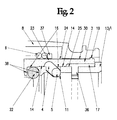
- FIG. 2 shows a greatly enlarged detail view from FIG. 1.
- Fig. 3 shows a quick connector according to the invention in the locked state, with the connector type I in half section.
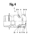
- Fig. 4 shows a half section of the sleeve body.
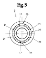
- Fig. 5 shows a view of the sleeve body towards the insertion side of the adapter.
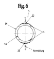
- Fig. 6 shows a cross section through the sleeve body in the area of the oblique slots.
- Fig. 7 shows a cross section through the sleeve body in the area of the openings for receiving the snap-in cams.
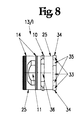
- Fig. 8 shows the view of the adapter.
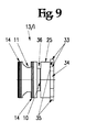
- FIG. 9 shows the view of the adapter from FIG. 8, but rotated 90 ° about its central axis.
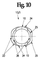
- FIG. 10 shows a cross section of the adapter in the area of the snap-in cams.
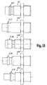
- FIG 11 shows the five different plugs with the five different plug profiles types I, II, III, IV, and V, which fit into the socket body according to the invention.
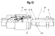
- Fig. 12 shows a quick connector according to the invention in the unlocked state, with the connector type II in half section.
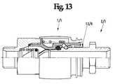
- FIG. 13 shows a quick coupling according to the invention in the locked state, with the connector type II in half section.
- the quick coupling shown serves for the coupling of two hose or pipe lines, not shown, and consists of a sleeve 1 / I to 1 / V and a connector 2 / I to 2 / V assigned to this sleeve, which is sealed with the help of the sealing ring 22, in the sleeve is insertable.
- this sleeve will only be named with number 1 and the connector only with number 2.
- the sleeve 1 is usually installed in a stationary manner, for example on a pipeline, while the plug 2 is usually mounted on the hose or on the tool, also not shown.
- the sleeve 1 has a substantially hollow cylindrical sleeve body 3 injection molded from plastic, at one end of which a connecting part 20, sealed by a seal 18, is screwed. Both the connecting part 20 and the plug 2 can be provided with a wide variety of connections 15 and 26, for example internal thread, external thread or hose nozzle. Predominantly quick couplings are designed as quick-release couplings, ie the sleeve has a shut-off valve 28 provided with a sealing ring 29, which closes in the uncoupled state and is opened when the plug 2 is pressed in. This valve, which is acted upon by a compression spring 27, is arranged in the sleeve body in the direction of the connecting part 20.
- a sealing ring 22 is arranged in the sleeve body in the direction of the adapter (13 / I to 13 / V) such that this sealing ring is held between two shoulders 38.
- the sleeve body 3 is pierced by the two, opposite, oblique slots 4 such that the oblique slots in De-mold direction penetrate the sleeve body, but a segment-like bridge 23 is formed over the oblique slots 4 in the region of the mold division.
- two openings 9 penetrating the hollow cylinder are arranged.
- An adapter 13 / I to 13 / V which is structurally adapted to the respective connector profile 31 / I to 31 / V, is arranged in the socket body 3 on the entry side of the connector.
- this adapter is only named with number 13 and the connector profile with number 31 in the following text.
- the adapters 13 / II, 13 / III, 13 / IV and 13 / V are not shown separately in the drawing. These adapters are made entirely on automatic lathes.
- the snap-in cams 10 of the adapter are formed by working out the two opposite recesses 36 on an automatic lathe.
- the opposing recesses 11 for receiving the locking pins 5 are also manufactured.
- the adapter 13 is inserted axially into the sleeve body 3 so that its snap-in cams 10 snap into the openings 9.
- a bayonet lock is conceivable, in such a way that the adapter 13 is first inserted axially into the sleeve body 3, then snap the snap-in cams 10 into the openings 9 by rotating the adapter. After the adapter has been installed, the cutouts 11 align with the oblique slots 4 of the sleeve body. The locking pins 5 can thus penetrate both bodies.
- Recesses 11 of the adapter and oblique slots 4 of the sleeve body thus jointly offer functions for the locking pins 5; such that the oblique slots 4 fulfill the guidance, the recesses 11, however, meet the stop for the tensile forces of the plug 2.
- the adapter 13 can only be pressed into the sleeve body 3 in its preferred position, it has a hexagon 33 (wrench size of the raw material) at its end protruding from the sleeve body, in which the corners have a dimension 35 that is between the wrench size 33 and the associated corner dimension is over-tightened.
- two corners are also flattened and form the surfaces 34. The width across flats of the two surfaces 34 is smaller than the width across flats of the hexagon 33.
- the locking device is mounted, ie the compression spring 6, the compression ring 37 and both locking pins 5 are inserted.
- the compression spring 6 always presses the locking pins 5 into the locking position specified by the respective adapter 13.
- the sleeve 8 is pushed with its inner bore 30 over the segment-like elevations 19, these segment-like elevations are pressed radially inward into the semicircular bulges 21 and the assembly of the coupling is completed.
- the front oblique shoulder 39 of the respective plug type from FIG. 11 presses the locking pins 5 outwards until the plug bead 12 has passed through both locking pins 5.
- this invention can also be used with a quick-action coupling that shuts off on both sides, ie with a coupling with one valve in each case in the socket and in the plug, and also with a coupling with a free passage, ie a socket without a valve.
Landscapes
- Engineering & Computer Science (AREA)
- General Engineering & Computer Science (AREA)
- Mechanical Engineering (AREA)
- Quick-Acting Or Multi-Walled Pipe Joints (AREA)
Priority Applications (4)
| Application Number | Priority Date | Filing Date | Title |
|---|---|---|---|
| AT96106347T ATE206190T1 (de) | 1996-04-23 | 1996-04-23 | Schnellkupplung für die verbindung von schlauch- und rohrleitungen |
| DE59607777T DE59607777D1 (de) | 1996-04-23 | 1996-04-23 | Schnellkupplung für die Verbindung von Schlauch- und Rohrleitungen |
| EP96106347A EP0803676B1 (fr) | 1996-04-23 | 1996-04-23 | Raccord rapide pour tuyaux flexibles ou canalisations |
| US09/176,754 US6131961A (en) | 1996-04-23 | 1998-10-22 | Quick connector for the connecting of hoses and pipe conduits |
Applications Claiming Priority (2)
| Application Number | Priority Date | Filing Date | Title |
|---|---|---|---|
| EP96106347A EP0803676B1 (fr) | 1996-04-23 | 1996-04-23 | Raccord rapide pour tuyaux flexibles ou canalisations |
| US09/176,754 US6131961A (en) | 1996-04-23 | 1998-10-22 | Quick connector for the connecting of hoses and pipe conduits |
Publications (2)
| Publication Number | Publication Date |
|---|---|
| EP0803676A1 true EP0803676A1 (fr) | 1997-10-29 |
| EP0803676B1 EP0803676B1 (fr) | 2001-09-26 |
Family
ID=26141883
Family Applications (1)
| Application Number | Title | Priority Date | Filing Date |
|---|---|---|---|
| EP96106347A Expired - Lifetime EP0803676B1 (fr) | 1996-04-23 | 1996-04-23 | Raccord rapide pour tuyaux flexibles ou canalisations |
Country Status (2)
| Country | Link |
|---|---|
| US (1) | US6131961A (fr) |
| EP (1) | EP0803676B1 (fr) |
Cited By (3)
| Publication number | Priority date | Publication date | Assignee | Title |
|---|---|---|---|---|
| DE19854685A1 (de) * | 1998-11-26 | 2000-05-31 | Christian Heilmann | Schnellkupplung für die Verbindung von Schlauch- und rohrleitungen |
| WO2004109178A1 (fr) * | 2003-06-10 | 2004-12-16 | Silvatech Global Systems Ltd. | Couplage a decouplage rapide telecommande |
| WO2018103816A1 (fr) * | 2016-12-05 | 2018-06-14 | Alfred Kärcher Gmbh & Co. Kg | Partie mâle pour un accouplement enfichable et accouplement enfichable comprenant une partie mâle |
Families Citing this family (24)
| Publication number | Priority date | Publication date | Assignee | Title |
|---|---|---|---|---|
| FR2786848B1 (fr) * | 1998-12-02 | 2001-02-09 | Legris Sa | Coupleur a billes |
| US6354521B1 (en) * | 2000-04-14 | 2002-03-12 | 3M Innovative Properties Company | Quick disconnect and release hose couplings |
| ES2433741T3 (es) | 2001-02-19 | 2013-12-12 | Canon Kabushiki Kaisha | Contenedor para suministro de tóner y sistema de suministro de tóner |
| EP1300623B1 (fr) * | 2001-02-28 | 2010-05-12 | Nitto Kohki Co., Ltd. | Joint de tuyaux |
| US6709019B2 (en) | 2001-09-21 | 2004-03-23 | Apical Industries, Inc. | Quick connector with automatic release |
| TWM242637U (en) * | 2002-05-17 | 2004-09-01 | Asia Pacific Fuel Cell Tech | Fast joint for hydrogen fuel bottle and adaptor apparatus for hydrogen fuel bottle with the same |
| JP4021748B2 (ja) * | 2002-11-25 | 2007-12-12 | 日東工器株式会社 | 管継手 |
| US7357659B2 (en) * | 2003-04-17 | 2008-04-15 | Canare Electric Co., Ltd. | Connector and female plug |
| US7712794B2 (en) * | 2003-05-02 | 2010-05-11 | Asia Pacific Fuel Cell Technologies, Ltd. | Rapid coupling device for hydrogen storage canister |
| US6890004B2 (en) * | 2003-08-01 | 2005-05-10 | Smc Kabushiki Kaisha | Coupler |
| US7887104B1 (en) * | 2004-08-16 | 2011-02-15 | Hollis Wilson | Quick connect and disconnect coupler |
| FR2890719B1 (fr) * | 2005-09-14 | 2007-10-12 | Staubli Faverges Sca | Raccord rapide de securite pour la jonction de deux canalisations |
| GB0623517D0 (en) * | 2006-11-25 | 2007-01-03 | Balltec Ltd | A connector |
| EP2053702B1 (fr) | 2007-10-24 | 2012-06-20 | Sumitomo Wiring Systems, Ltd. | Dispositif de connecteur et structure de verrouillage |
| JP5317761B2 (ja) * | 2008-02-28 | 2013-10-16 | 日東工器株式会社 | 管継手用のソケット及び管継手 |
| JP5317760B2 (ja) * | 2008-02-28 | 2013-10-16 | 日東工器株式会社 | 管継手用のソケット及び管継手 |
| DE102008027676A1 (de) * | 2008-06-03 | 2009-12-10 | Karl Storz Gmbh & Co. Kg | Kupplung für ein medizinisches Instrument |
| ES2373168B2 (es) | 2011-12-15 | 2012-07-04 | Pedro Gregorio Casamian | Racor de acoplamiento rápido con sistema de seguridad para tuberías neumáticas. |
| CN102767655A (zh) * | 2012-08-04 | 2012-11-07 | 合肥长城制冷科技有限公司 | 用于保压接头的卡套组合件 |
| US9523453B2 (en) | 2013-03-20 | 2016-12-20 | Miniature Precision Components, Inc. | Locking quick connect assembly |
| DE102014109965B4 (de) * | 2014-07-16 | 2019-03-21 | Silag Handel Ag | Nutzgefäß, insbesondere Trinkglas |
| US10995890B2 (en) | 2017-09-19 | 2021-05-04 | Mat Industries, Llc | Quick-connect coupler |
| US10790615B2 (en) | 2018-12-28 | 2020-09-29 | Raytheon Company | Cable quick connector adapter |
| US12465176B2 (en) * | 2022-11-14 | 2025-11-11 | Haier Us Appliance Solutions, Inc. | Quick release attachment assembly and system for a stand mixer |
Citations (4)
| Publication number | Priority date | Publication date | Assignee | Title |
|---|---|---|---|---|
| US3336944A (en) * | 1964-04-06 | 1967-08-22 | Wiggins Inc E B | Quick connect valved coupling |
| DE1902986A1 (de) * | 1969-01-22 | 1970-08-20 | Rectus Appbau Walter Klein | Schnellverschlusskupplung fuer Druckgas-,insbesondere Druckluftleitungen |
| US3643695A (en) * | 1970-03-23 | 1972-02-22 | Commercial Screw Products Inc | Fluid line coupler |
| US4667925A (en) * | 1985-08-02 | 1987-05-26 | G.F. S.R.L. | Quick coupling hose connection with double acting backflow preventing valve |
Family Cites Families (9)
| Publication number | Priority date | Publication date | Assignee | Title |
|---|---|---|---|---|
| US2092116A (en) * | 1935-11-07 | 1937-09-07 | Fred E Hansen | Hose coupling |
| US2708589A (en) * | 1949-05-11 | 1955-05-17 | Robert W Masek | Tension actuated pipe coupling |
| US2777716A (en) * | 1949-10-11 | 1957-01-15 | Grav Company Inc | Socket type hose coupler with reciprocating detent |
| US4366945A (en) * | 1978-12-20 | 1983-01-04 | Abnox Ag | Hose coupling with double lock |
| FR2461876A1 (fr) * | 1979-07-23 | 1981-02-06 | Staubli Sa Ets | Perfectionnements aux dispositifs de raccord rapide pour la jonction des canalisations |
| SE465839B (sv) * | 1989-09-19 | 1991-11-04 | Ezze Ab | Snabbkoppling |
| DK0536434T3 (da) * | 1991-10-08 | 1994-10-24 | Klein Rectus App | Selvafluftende lynkobling til trykgas-, navnlig trykluftledninger |
| DE4444049A1 (de) * | 1994-12-10 | 1996-06-20 | Wolf Gmbh Richard | Vorrichtung für die Verbindung eines Endoskops mit einem Zusatzgerät |
| US5445358A (en) * | 1994-12-16 | 1995-08-29 | Parker-Hannifin Corporation | Exhaust type quick action coupler |
-
1996
- 1996-04-23 EP EP96106347A patent/EP0803676B1/fr not_active Expired - Lifetime
-
1998
- 1998-10-22 US US09/176,754 patent/US6131961A/en not_active Expired - Fee Related
Patent Citations (4)
| Publication number | Priority date | Publication date | Assignee | Title |
|---|---|---|---|---|
| US3336944A (en) * | 1964-04-06 | 1967-08-22 | Wiggins Inc E B | Quick connect valved coupling |
| DE1902986A1 (de) * | 1969-01-22 | 1970-08-20 | Rectus Appbau Walter Klein | Schnellverschlusskupplung fuer Druckgas-,insbesondere Druckluftleitungen |
| US3643695A (en) * | 1970-03-23 | 1972-02-22 | Commercial Screw Products Inc | Fluid line coupler |
| US4667925A (en) * | 1985-08-02 | 1987-05-26 | G.F. S.R.L. | Quick coupling hose connection with double acting backflow preventing valve |
Cited By (5)
| Publication number | Priority date | Publication date | Assignee | Title |
|---|---|---|---|---|
| DE19854685A1 (de) * | 1998-11-26 | 2000-05-31 | Christian Heilmann | Schnellkupplung für die Verbindung von Schlauch- und rohrleitungen |
| WO2004109178A1 (fr) * | 2003-06-10 | 2004-12-16 | Silvatech Global Systems Ltd. | Couplage a decouplage rapide telecommande |
| WO2018103816A1 (fr) * | 2016-12-05 | 2018-06-14 | Alfred Kärcher Gmbh & Co. Kg | Partie mâle pour un accouplement enfichable et accouplement enfichable comprenant une partie mâle |
| CN110050153A (zh) * | 2016-12-05 | 2019-07-23 | 阿尔弗雷德·卡赫欧洲两合公司 | 用于插塞耦联装置的插塞器部件以及具有插塞器部件的插塞耦联装置 |
| CN110050153B (zh) * | 2016-12-05 | 2021-08-10 | 阿尔弗雷德·卡赫欧洲两合公司 | 用于插塞耦联装置的插塞器部件以及具有插塞器部件的插塞耦联装置 |
Also Published As
| Publication number | Publication date |
|---|---|
| EP0803676B1 (fr) | 2001-09-26 |
| US6131961A (en) | 2000-10-17 |
Similar Documents
| Publication | Publication Date | Title |
|---|---|---|
| EP0803676B1 (fr) | Raccord rapide pour tuyaux flexibles ou canalisations | |
| DE2856064C2 (fr) | ||
| DE2317959C2 (de) | Verdrehbare Leitungskupplung | |
| DE2011409C3 (de) | Ventilschnellkupplung fur zwei gas- oder flussigkeitsfuhrende Leitungen | |
| DE3901652C2 (de) | Druckausgeglichene Hydraulikkupplung mit Metalldichtungen | |
| DE4334529C2 (de) | Verbindungsvorrichtung für ein flexibles Wellrohr | |
| EP0375666B1 (fr) | Dispositif de connexion enfichable avec verrouillage de torsion | |
| DE1775980A1 (de) | Schlauchkupplung | |
| CH636683A5 (de) | Anschlussverbindungsstueck fuer leitungen zum fuehren von gasfoermigen oder fluessigen medien. | |
| DE3838935A1 (de) | Kupplungsstueck | |
| DE3725897C2 (fr) | ||
| DE60204287T2 (de) | Kupplung zur verbindung eines rohrs oder schlauchs durch einschieben | |
| DE60205641T2 (de) | Zur verbindung zweier röhrenförmiger elemente verwendete kupplung und montageverfahren dafür | |
| DE2811985C2 (fr) | ||
| DE3627274C2 (fr) | ||
| DE3923579A1 (de) | Anschlussarmatur fuer rohre, insbesondere fuer kunststoffrohre | |
| EP0688994B1 (fr) | Raccord de connexion pour un corps de soupape en plastique | |
| DE3734548A1 (de) | Anschlussverbindungsstueck | |
| DE4023264C2 (fr) | ||
| DE2840648C3 (de) | Anschlußverbindungsstück für Leitungen zum Führen von gasförmigen oder flüssigen Medien | |
| DE2449443B2 (de) | Umkehrbar in eine Bohrung eines Modulblocks einsetzbares Rückschlagventil | |
| EP1029192A1 (fr) | Piece de raccordement et d'assemblage pour tubes ondules | |
| DE3536286C2 (fr) | ||
| DE19819758A1 (de) | Steckverbindung für Rohrleitungen | |
| DE19715293B4 (de) | Steckverbindung für Rohrleitungen |
Legal Events
| Date | Code | Title | Description |
|---|---|---|---|
| PUAI | Public reference made under article 153(3) epc to a published international application that has entered the european phase |
Free format text: ORIGINAL CODE: 0009012 |
|
| AK | Designated contracting states |
Kind code of ref document: A1 Designated state(s): AT CH DE FR GB LI SE |
|
| 17P | Request for examination filed |
Effective date: 19971117 |
|
| 17Q | First examination report despatched |
Effective date: 19990917 |
|
| GRAG | Despatch of communication of intention to grant |
Free format text: ORIGINAL CODE: EPIDOS AGRA |
|
| GRAG | Despatch of communication of intention to grant |
Free format text: ORIGINAL CODE: EPIDOS AGRA |
|
| GRAH | Despatch of communication of intention to grant a patent |
Free format text: ORIGINAL CODE: EPIDOS IGRA |
|
| GRAH | Despatch of communication of intention to grant a patent |
Free format text: ORIGINAL CODE: EPIDOS IGRA |
|
| GRAA | (expected) grant |
Free format text: ORIGINAL CODE: 0009210 |
|
| RAP1 | Party data changed (applicant data changed or rights of an application transferred) |
Owner name: HEILMANN, CHRISTIAN |
|
| RIN1 | Information on inventor provided before grant (corrected) |
Inventor name: HEILMANN, CHRISTIAN |
|
| AK | Designated contracting states |
Kind code of ref document: B1 Designated state(s): AT CH DE FR GB LI SE |
|
| PG25 | Lapsed in a contracting state [announced via postgrant information from national office to epo] |
Ref country code: GB Free format text: LAPSE BECAUSE OF FAILURE TO SUBMIT A TRANSLATION OF THE DESCRIPTION OR TO PAY THE FEE WITHIN THE PRESCRIBED TIME-LIMIT Effective date: 20010926 Ref country code: FR Free format text: LAPSE BECAUSE OF FAILURE TO SUBMIT A TRANSLATION OF THE DESCRIPTION OR TO PAY THE FEE WITHIN THE PRESCRIBED TIME-LIMIT Effective date: 20010926 |
|
| REF | Corresponds to: |
Ref document number: 206190 Country of ref document: AT Date of ref document: 20011015 Kind code of ref document: T |
|
| REG | Reference to a national code |
Ref country code: CH Ref legal event code: EP |
|
| REF | Corresponds to: |
Ref document number: 59607777 Country of ref document: DE Date of ref document: 20011031 |
|
| PG25 | Lapsed in a contracting state [announced via postgrant information from national office to epo] |
Ref country code: SE Free format text: LAPSE BECAUSE OF FAILURE TO SUBMIT A TRANSLATION OF THE DESCRIPTION OR TO PAY THE FEE WITHIN THE PRESCRIBED TIME-LIMIT Effective date: 20011226 |
|
| GBV | Gb: ep patent (uk) treated as always having been void in accordance with gb section 77(7)/1977 [no translation filed] |
Effective date: 20010926 |
|
| PG25 | Lapsed in a contracting state [announced via postgrant information from national office to epo] |
Ref country code: AT Free format text: LAPSE BECAUSE OF NON-PAYMENT OF DUE FEES Effective date: 20020423 |
|
| PG25 | Lapsed in a contracting state [announced via postgrant information from national office to epo] |
Ref country code: LI Free format text: LAPSE BECAUSE OF NON-PAYMENT OF DUE FEES Effective date: 20020430 Ref country code: CH Free format text: LAPSE BECAUSE OF NON-PAYMENT OF DUE FEES Effective date: 20020430 |
|
| EN | Fr: translation not filed | ||
| PLBE | No opposition filed within time limit |
Free format text: ORIGINAL CODE: 0009261 |
|
| STAA | Information on the status of an ep patent application or granted ep patent |
Free format text: STATUS: NO OPPOSITION FILED WITHIN TIME LIMIT |
|
| 26N | No opposition filed | ||
| REG | Reference to a national code |
Ref country code: CH Ref legal event code: PL |
|
| PGFP | Annual fee paid to national office [announced via postgrant information from national office to epo] |
Ref country code: DE Payment date: 20070430 Year of fee payment: 12 |
|
| PG25 | Lapsed in a contracting state [announced via postgrant information from national office to epo] |
Ref country code: DE Free format text: LAPSE BECAUSE OF NON-PAYMENT OF DUE FEES Effective date: 20081101 |