EP0803678A2 - Dispositif pour le support d'une bouteille de gaz - Google Patents
Dispositif pour le support d'une bouteille de gaz Download PDFInfo
- Publication number
- EP0803678A2 EP0803678A2 EP97106724A EP97106724A EP0803678A2 EP 0803678 A2 EP0803678 A2 EP 0803678A2 EP 97106724 A EP97106724 A EP 97106724A EP 97106724 A EP97106724 A EP 97106724A EP 0803678 A2 EP0803678 A2 EP 0803678A2
- Authority
- EP
- European Patent Office
- Prior art keywords
- base plate
- hand lever
- bottle
- lifting
- gas bottle
- Prior art date
- Legal status (The legal status is an assumption and is not a legal conclusion. Google has not performed a legal analysis and makes no representation as to the accuracy of the status listed.)
- Withdrawn
Links
- 238000003466 welding Methods 0.000 claims description 18
- 230000000284 resting effect Effects 0.000 abstract 4
- 239000007789 gas Substances 0.000 description 68
- QVGXLLKOCUKJST-UHFFFAOYSA-N atomic oxygen Chemical compound [O] QVGXLLKOCUKJST-UHFFFAOYSA-N 0.000 description 3
- 239000001301 oxygen Substances 0.000 description 3
- 229910052760 oxygen Inorganic materials 0.000 description 3
- IJGRMHOSHXDMSA-UHFFFAOYSA-N Atomic nitrogen Chemical compound N#N IJGRMHOSHXDMSA-UHFFFAOYSA-N 0.000 description 2
- CURLTUGMZLYLDI-UHFFFAOYSA-N Carbon dioxide Chemical compound O=C=O CURLTUGMZLYLDI-UHFFFAOYSA-N 0.000 description 2
- ZAMOUSCENKQFHK-UHFFFAOYSA-N Chlorine atom Chemical compound [Cl] ZAMOUSCENKQFHK-UHFFFAOYSA-N 0.000 description 2
- 239000000460 chlorine Substances 0.000 description 2
- 229910052801 chlorine Inorganic materials 0.000 description 2
- 238000000034 method Methods 0.000 description 2
- 238000005096 rolling process Methods 0.000 description 2
- KZBUYRJDOAKODT-UHFFFAOYSA-N Chlorine Chemical compound ClCl KZBUYRJDOAKODT-UHFFFAOYSA-N 0.000 description 1
- MYMOFIZGZYHOMD-UHFFFAOYSA-N Dioxygen Chemical compound O=O MYMOFIZGZYHOMD-UHFFFAOYSA-N 0.000 description 1
- 235000004443 Ricinus communis Nutrition 0.000 description 1
- 240000000528 Ricinus communis Species 0.000 description 1
- 239000006096 absorbing agent Substances 0.000 description 1
- 239000001569 carbon dioxide Substances 0.000 description 1
- 229910002092 carbon dioxide Inorganic materials 0.000 description 1
- 238000004140 cleaning Methods 0.000 description 1
- 230000001419 dependent effect Effects 0.000 description 1
- 229910001882 dioxygen Inorganic materials 0.000 description 1
- 230000003203 everyday effect Effects 0.000 description 1
- 230000002349 favourable effect Effects 0.000 description 1
- 230000005484 gravity Effects 0.000 description 1
- 239000001307 helium Substances 0.000 description 1
- 229910052734 helium Inorganic materials 0.000 description 1
- SWQJXJOGLNCZEY-UHFFFAOYSA-N helium atom Chemical compound [He] SWQJXJOGLNCZEY-UHFFFAOYSA-N 0.000 description 1
- 239000001257 hydrogen Substances 0.000 description 1
- 229910052739 hydrogen Inorganic materials 0.000 description 1
- 125000004435 hydrogen atom Chemical class [H]* 0.000 description 1
- 239000000203 mixture Substances 0.000 description 1
- 229910052757 nitrogen Inorganic materials 0.000 description 1
- 230000001681 protective effect Effects 0.000 description 1
- 238000005086 pumping Methods 0.000 description 1
- 230000035939 shock Effects 0.000 description 1
- 238000003860 storage Methods 0.000 description 1
- 230000009182 swimming Effects 0.000 description 1
- 238000011282 treatment Methods 0.000 description 1
- XLYOFNOQVPJJNP-UHFFFAOYSA-N water Substances O XLYOFNOQVPJJNP-UHFFFAOYSA-N 0.000 description 1
Images



Classifications
-
- F—MECHANICAL ENGINEERING; LIGHTING; HEATING; WEAPONS; BLASTING
- F16—ENGINEERING ELEMENTS AND UNITS; GENERAL MEASURES FOR PRODUCING AND MAINTAINING EFFECTIVE FUNCTIONING OF MACHINES OR INSTALLATIONS; THERMAL INSULATION IN GENERAL
- F16M—FRAMES, CASINGS OR BEDS OF ENGINES, MACHINES OR APPARATUS, NOT SPECIFIC TO ENGINES, MACHINES OR APPARATUS PROVIDED FOR ELSEWHERE; STANDS; SUPPORTS
- F16M11/00—Stands or trestles as supports for apparatus or articles placed thereon ; Stands for scientific apparatus such as gravitational force meters
- F16M11/42—Stands or trestles as supports for apparatus or articles placed thereon ; Stands for scientific apparatus such as gravitational force meters with arrangement for propelling the support stands on wheels
-
- B—PERFORMING OPERATIONS; TRANSPORTING
- B23—MACHINE TOOLS; METAL-WORKING NOT OTHERWISE PROVIDED FOR
- B23K—SOLDERING OR UNSOLDERING; WELDING; CLADDING OR PLATING BY SOLDERING OR WELDING; CUTTING BY APPLYING HEAT LOCALLY, e.g. FLAME CUTTING; WORKING BY LASER BEAM
- B23K7/00—Cutting, scarfing, or desurfacing by applying flames
- B23K7/10—Auxiliary devices, e.g. for guiding or supporting the torch
-
- F—MECHANICAL ENGINEERING; LIGHTING; HEATING; WEAPONS; BLASTING
- F16—ENGINEERING ELEMENTS AND UNITS; GENERAL MEASURES FOR PRODUCING AND MAINTAINING EFFECTIVE FUNCTIONING OF MACHINES OR INSTALLATIONS; THERMAL INSULATION IN GENERAL
- F16M—FRAMES, CASINGS OR BEDS OF ENGINES, MACHINES OR APPARATUS, NOT SPECIFIC TO ENGINES, MACHINES OR APPARATUS PROVIDED FOR ELSEWHERE; STANDS; SUPPORTS
- F16M11/00—Stands or trestles as supports for apparatus or articles placed thereon ; Stands for scientific apparatus such as gravitational force meters
- F16M11/02—Heads
- F16M11/04—Means for attachment of apparatus; Means allowing adjustment of the apparatus relatively to the stand
- F16M11/043—Allowing translations
- F16M11/046—Allowing translations adapted to upward-downward translation movement
-
- F—MECHANICAL ENGINEERING; LIGHTING; HEATING; WEAPONS; BLASTING
- F16—ENGINEERING ELEMENTS AND UNITS; GENERAL MEASURES FOR PRODUCING AND MAINTAINING EFFECTIVE FUNCTIONING OF MACHINES OR INSTALLATIONS; THERMAL INSULATION IN GENERAL
- F16M—FRAMES, CASINGS OR BEDS OF ENGINES, MACHINES OR APPARATUS, NOT SPECIFIC TO ENGINES, MACHINES OR APPARATUS PROVIDED FOR ELSEWHERE; STANDS; SUPPORTS
- F16M11/00—Stands or trestles as supports for apparatus or articles placed thereon ; Stands for scientific apparatus such as gravitational force meters
- F16M11/02—Heads
- F16M11/18—Heads with mechanism for moving the apparatus relatively to the stand
-
- F—MECHANICAL ENGINEERING; LIGHTING; HEATING; WEAPONS; BLASTING
- F17—STORING OR DISTRIBUTING GASES OR LIQUIDS
- F17C—VESSELS FOR CONTAINING OR STORING COMPRESSED, LIQUEFIED OR SOLIDIFIED GASES; FIXED-CAPACITY GAS-HOLDERS; FILLING VESSELS WITH, OR DISCHARGING FROM VESSELS, COMPRESSED, LIQUEFIED, OR SOLIDIFIED GASES
- F17C13/00—Details of vessels or of the filling or discharging of vessels
- F17C13/08—Mounting arrangements for vessels
- F17C13/084—Mounting arrangements for vessels for small-sized storage vessels, e.g. compressed gas cylinders or bottles, disposable gas vessels, vessels adapted for automotive use
-
- F—MECHANICAL ENGINEERING; LIGHTING; HEATING; WEAPONS; BLASTING
- F16—ENGINEERING ELEMENTS AND UNITS; GENERAL MEASURES FOR PRODUCING AND MAINTAINING EFFECTIVE FUNCTIONING OF MACHINES OR INSTALLATIONS; THERMAL INSULATION IN GENERAL
- F16M—FRAMES, CASINGS OR BEDS OF ENGINES, MACHINES OR APPARATUS, NOT SPECIFIC TO ENGINES, MACHINES OR APPARATUS PROVIDED FOR ELSEWHERE; STANDS; SUPPORTS
- F16M2200/00—Details of stands or supports
- F16M2200/02—Locking means
- F16M2200/025—Locking means for translational movement
- F16M2200/028—Locking means for translational movement by positive interaction, e.g. male-female connections
-
- F—MECHANICAL ENGINEERING; LIGHTING; HEATING; WEAPONS; BLASTING
- F17—STORING OR DISTRIBUTING GASES OR LIQUIDS
- F17C—VESSELS FOR CONTAINING OR STORING COMPRESSED, LIQUEFIED OR SOLIDIFIED GASES; FIXED-CAPACITY GAS-HOLDERS; FILLING VESSELS WITH, OR DISCHARGING FROM VESSELS, COMPRESSED, LIQUEFIED, OR SOLIDIFIED GASES
- F17C2201/00—Vessel construction, in particular geometry, arrangement or size
- F17C2201/03—Orientation
- F17C2201/032—Orientation with substantially vertical main axis
-
- F—MECHANICAL ENGINEERING; LIGHTING; HEATING; WEAPONS; BLASTING
- F17—STORING OR DISTRIBUTING GASES OR LIQUIDS
- F17C—VESSELS FOR CONTAINING OR STORING COMPRESSED, LIQUEFIED OR SOLIDIFIED GASES; FIXED-CAPACITY GAS-HOLDERS; FILLING VESSELS WITH, OR DISCHARGING FROM VESSELS, COMPRESSED, LIQUEFIED, OR SOLIDIFIED GASES
- F17C2205/00—Vessel construction, in particular mounting arrangements, attachments or identifications means
- F17C2205/01—Mounting arrangements
- F17C2205/0153—Details of mounting arrangements
- F17C2205/0157—Details of mounting arrangements for transport
- F17C2205/0161—Details of mounting arrangements for transport with wheels
-
- F—MECHANICAL ENGINEERING; LIGHTING; HEATING; WEAPONS; BLASTING
- F17—STORING OR DISTRIBUTING GASES OR LIQUIDS
- F17C—VESSELS FOR CONTAINING OR STORING COMPRESSED, LIQUEFIED OR SOLIDIFIED GASES; FIXED-CAPACITY GAS-HOLDERS; FILLING VESSELS WITH, OR DISCHARGING FROM VESSELS, COMPRESSED, LIQUEFIED, OR SOLIDIFIED GASES
- F17C2205/00—Vessel construction, in particular mounting arrangements, attachments or identifications means
- F17C2205/01—Mounting arrangements
- F17C2205/0153—Details of mounting arrangements
- F17C2205/0157—Details of mounting arrangements for transport
- F17C2205/0165—Details of mounting arrangements for transport with handgrip
Definitions
- the invention relates to a device for holding a gas bottle, a stand plate for the gas bottle being provided on the device.
- gas in everyday life is widespread. It is known to use gas, for example in industry, in trade, in handicrafts, in service companies and in the medical field, in indoor swimming pools and many other areas.
- the gas is delivered in gas bottles.
- the gas in the gas bottles fulfills a wide variety of tasks.
- the gas is used, for example, for welding.
- the gas results in a closed atmosphere, for example, in the Weld spot creates an optimal weld.
- Oxygen, nitrogen, hydrogen, helium, chlorine, carbon dioxide and many other gaseous elements or compositions are transported or stored in gas bottles. For example, it is known to carry out special oxygen treatments in hospitals in which the oxygen is kept in oxygen gas bottles. In indoor pools, the water is disinfected by chlorine from chlorine gas bottles.
- the use of all of these gas cylinders has a common problem.
- the invention has set itself the task of improving devices as described in the introduction so that loading the device with the gas bottle is possible without any problems.
- the invention is based on a device as described in the introduction and suggests that the base plate is adjustable in height and a lifting device is provided for the height adjustment.
- the configuration according to the invention makes it possible for the base plate to be lowered to the floor for loading with the gas bottle, for the gas bottle to be moved under by simply tilting, or for the gas bottle to be rolled up onto the base plate.
- the base plate of the gas bottle can now be lifted using the lifting device, and the height-adjustable base plate is raised so far from the floor that it e.g. has the same ground clearance as the wheeled device.
- the solution according to the invention means that there is no need to lift the gas bottle, which means that the operator's health is eliminated. Possible accident risks that can arise from the gas bottle slipping off are also completely avoided, since manual lifting of the gas bottle is no longer necessary.
- a rotatably mounted hand lever is provided as the lifting device, which acts on the base plate via a lifting element.
- a lifting element For example, a cable pull, a linkage, a gearbox or a hydraulic system is provided as the lifting element.
- the hand lever is actuated by a pumping movement or a folding movement and causes the height of the base plate to be adjusted by the lifting element.
- a crank drive with a hand lever can also be provided, the crank drive or the spindle drive acting on the height adjustment of the base plate via a reel with a cable pull or via a worm gear as a lifting device.
- an electrical lifting device is provided.
- the gas bottles are used, for example, for welding.
- the welding equipment is usually connected to the power grid. Often the current does the actual welding, and the gas only creates a protective gas atmosphere.
- An electric motor with a gear can be provided on the lifting device, which is connected to the power supply of the welding apparatus and, with a simple control, causes the base plate and the gas bottle located thereon to be raised and lowered.
- the device according to the invention is designed both as a retrofit unit, i.e. the device is suitable for being attached to existing welding devices, or the device is integrated in welding devices to be newly manufactured.
- the device according to the invention serves both to accommodate only one and also several gas bottles.
- the device is designed to be stationary, in particular fastened in a wall.
- the device is provided on a mobile frame.
- the possible uses of the device are by no means limited. Wherever gas cylinders are either transported or stored, there is the problem that they have to be placed on a base plate, as a result of which the problems described at the outset arise.
- the device according to the embodiment of the invention can thus be designed to be stationary, that is to say essentially immobile. For this, e.g. provided that the device is designed to be anchored on a wall or in the floor.
- the transport device has an embodiment according to the invention. Transporting the gas bottles in particular can be very dangerous, since loading and unloading harbors two sources of danger when handling the gas bottles.
- the device according to the invention is advantageous when used on welding apparatus.
- One or more gas cylinders can be used in welding equipment. The gas consumption is quite different and the gas bottles have to be changed.
- the welding apparatus can e.g. have a mobile frame or castors or the like. However, the welding apparatus can also be designed to be stationary. The configuration according to the invention makes it much easier to load or replace the gas bottles on the welding apparatus.
- the mobile frame serves as the lifting device, which can be pivoted about a horizontal axis and the base plate is designed with a holding lug which engages in a holding projection of a bottle receiving station when the lifting device is actuated and the lifting device is pivoted back of the rack lifts the gas bottle.
- the mobile frame not only has the task of transporting the bottles like a bottle cart, but also serves at the same time as a lifting device in order to raise the gas bottle to the corresponding storage level of the gas bottle at a bottle receiving station.
- a bottle receiving station is, for example, the base of the gas bottle on a welding machine or the bottle holder on a wall or the like.
- This bottle cart usually has an axle with two wheels, the axle simultaneously serving as a horizontal axis about which the mobile frame can be pivoted.
- the axle For transportation, it is favorable to swivel the cart backwards and thus to arrange the center of gravity of the loaded cart essentially above the axis of rotation, whereby an easy transportation of the gas bottle is possible.
- the front end of the base plate protrudes from the floor with one or more retaining lugs.
- This inclined position is used to bring the retaining lug into engagement with retaining projections provided at the bottle receiving station.
- Appropriate arrangement of the base plate or the swivel angle means that height differences of up to 30 cm can be overcome.
- the mobile frame is pivoted back about the horizontal axis, as a result of which the gas bottle is again placed vertically.
- the base plate pulls upwards on the holding projection, the base plate being fastened to the mobile frame with longitudinal guides.
- the lifting device has a lowering protection.
- This lowering lock is designed to be detachable and prevents the lifting device from sliding down unintentionally.
- a parking brake is provided for the wheels of the mobile frame and the base plate sinks by releasing the lowering lock before releasing the parking brake.
- An advantageous embodiment of the invention ensures that the parking brake and the lowering device can be actuated in succession by a common Bowden cable.
- the bowden pressure is connected to an operating lever.
- the parking brake presses on the wheel and prevents the mobile frame from rolling away.
- a release of the parking brake is necessary, the lowering lock being released first, as described, as a result of which the gas bottle is lowered and then the parking brake can be released.
- the use of a Bowden cable with variable length in the partial cables for the parking brake and lowering protection is a simple but safe solution.
- FIG. 1 shows the device according to the invention.
- the representation of a welding apparatus on which the device e.g. is provided has been waived.
- the gas bottle is not shown in the raised position shown here.
- the device consists essentially of a frame 1, which is, for example, rectangular and has 14 guides 2 on its essentially vertical bars.
- the frame 1 is made, for example, of welded bars, the guides 2 are welded onto these bars.
- the gas bottle stands on the base plate 3.
- the base plate 3 is L-shaped 30, the gas bottle standing on the substantially horizontally oriented base surface 31.
- the footprint 31 forms the shorter leg of the L-shaped 30 base plate 3.
- the essentially vertically arranged element 32 of the base plate 3 is guided in the guide 2 such that the L-like 30 base plate 3 perform a height adjustment along the double arrow 6 can.
- the base plate 3 is essentially flat and that corresponding lifting elements engage the base plate 3.
- the standing surface 31 has raised edges 33 on the sides.
- Appropriate means, such as safety chains, etc., are provided for securing the bottle further.
- a lifting device 4 is provided for raising or lowering the base plate 3.
- this lifting device 4 is designed as a cable pull 40, which acts on the upper end of the vertical element 32 at the point of application 41.
- the point of engagement 41 is arranged as far as possible in the middle of the vertical plate 32 at the upper edge.
- the cable 40 engages at the point of application 41 and is deflected essentially at right angles via a fixed, rotating roller.
- the roller 11 is provided on the upper horizontal spar 10 in such a way that the cable 40 runs essentially vertically.
- the hand lever 7 is provided on the right side.
- the hand lever 7 is also rotatably mounted on the upper horizontal bar 10 at a pivot point 70.
- the hand lever 7 is L-shaped 71, the shorter leg 72 being significantly shorter than the long leg 73, on which the handle 74 is also provided.
- the deflected rope 40 is attached to the short leg 72 at the attachment point 75.
- the base plate 3 is lowered by pivoting the hand lever 7 in a counterclockwise direction in accordance with the pivoting movement 76.
- This pivoting movement 76 shortens the distance of the attachment point 75 from the fulcrum 12 of the roller 11 and thereby extends the downward effective cable length 42. This results in the base plate 3 being lowered.
- a self-locking device 5 is advantageously provided for the hand lever 7.
- the self-locking 5 causes the Hand lever 7 is held stable in a self-fixed position. In this way, an unintentional lowering of the base plate is reliably avoided, since for lowering the base plate 3 the hand lever 7 must first be moved over the self-locking device 5 in order to achieve a lowering.
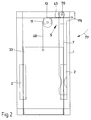
- Fig. 2 the self-locking 5 is shown schematically.
- the rope 40 has a downward rope length 42 and an essentially horizontal rope length 43, which in FIG. 3 is also inclined.
- the weight of the base plate with the gas bottle is directed onto the hand lever 7 via the cable 40.
- the fixed roller 11 is provided, which redirects the direction of action of the force.
- the force always runs parallel to the respective rope pieces, ie essentially horizontally between the roller 11 and the attachment point 75.
- the resulting weight force thus acts between the attachment point 75 and the contact point 13 of the rope 40 on the roller 11 and extends in the pulled-up, worn-out manner Position below the fulcrum 70 of the hand lever 7.
- This configuration advantageously produces a torque 77 which acts clockwise about the fulcrum 70 and which presses the hand lever 7 against the frame 1.
- a not shown stop on the frame 1 is provided.
- Fig. 3 the lowered position of the base plate 3 is shown.
- the base plate 3 can be loaded with the gas bottle.
- the frame 1 is designed so that it does not reach the floor, but maintains a certain distance from the floor. In this embodiment, the frame 1 does not affect the ground clearance of the movable welding apparatus, for example.
- the lower edge of the frame 1 includes z. B. with the lower edge of the housing of the welding apparatus.
- the upwardly pivoted hand lever 7 causes the base plate 3 to be lowered.
- the rope length 43 running between the attachment point 75 and the roller 11 is inclined upward from the horizontal by an angle of approximately 45 °.
- the rope length 43 is significantly shortened compared to the configuration in FIG. 2, as a result of which the lowering of the base plate 3 is achieved.
- a stop (not shown) is provided on the upper, horizontal spar 10, which prevents the hand lever 7 from tipping over.
- the device according to the invention can also be equipped with more than one deflection roller around which the rope for lifting the base plate is guided. It is also possible that the L-shaped base plate is dispensed with and an essentially flat base plate is used, to which the lifting means acts.
- the base plate in particular when the device is used tilted, simultaneously forms a guide or stop for the gas bottle.
- FIG. 4 shows a further embodiment of the invention.
- the device according to the invention is combined here with a bottle cart known per se.
- the special feature of this configuration is that a bottle can be easily transported in this combination and then raised to a corresponding level by the lifting device 104 in order to transfer it to a corresponding bottle receiving station.
- the frame 102 has wheels 110 which are rotatably mounted about an axis 111.
- the frame 101 or the bottle trolley 102 can also be pivoted about this axis 111, which at the same time acts here as a horizontal axis 112.
- the bottle trolley 102 has two struts 120 running essentially parallel and upwards.
- the struts 120 form the handles 121 in the upper region.
- the struts 120 are arranged in such a way that the gas bottle can be easily accommodated between them.
- the struts 120 are bent forward in the upper region of the bottle trolley 2 and then describe a U which adjoins in the direction of the handle 121.
- a funnel shape is achieved which optimally encloses and secures the gas bottles.
- loop chains (not shown) can be provided which reliably prevent the bottles from slipping out unintentionally.
- An actuating lever 122 is arranged on the handle 121. By means of this actuating lever 122, on the one hand a brake 103 and on the other hand the anti-lowering device 105 is released if necessary. The brake 103 and the anti-lowering device 105 are connected to the actuating lever 122 by a common Bowden cable 123. By actuating the actuating lever 122, both the brake 3 and the lowering safety device 5 are actuated simultaneously. In the unactuated state, the bottle trolley 102 is fixed by the brake 103. It is e.g. provided to arrange either only one brake, as shown in FIG. 5, or an acting brake 103 on each wheel. This configuration ensures that unintentional rolling away of the bottle trolley 2 is avoided.
- the Bowden cable 123 also acts on the lowering safeguard 105, which is released when the actuating lever 22 is pressed.
- the base plate 140 is lowered into the lowest position, which is advantageous for transporting the gas bottles.
- the gas bottle is placed on the bottle trolley 102 from the floor, this being achieved by simply tilting the gas bottle and simultaneously moving the base plate 40 under the gas bottle.
- the frame 101 is usually pivoted counterclockwise in the direction of the arrow 113 in order to transport the bottle.
- the base plate 140 has side cheeks in order to give the gas bottle a lateral hold in the lower region.
- the lifting device 104 includes in particular retaining lugs 141 at the front end of the base plate 140. It is provided that the base plate 140 e.g. L-shaped and has in the substantially vertical section guides 142, by means of which the base plate 140 on the frame 101 is substantially vertically displaceable.
- Fig. 4 the upper position of the base plate 140 is indicated by dashed lines. This position is achieved, for example, in that the holding lugs 141, when the bottle trolley 102 is pivoted for transport, engages in holding projections provided at the bottle receiving stations. At that moment the bottle has not yet been lifted. If the frame 1 is now pivoted clockwise around the horizontal axis 112, which corresponds here to the shaft 111 of the wheels 110, that is to say against the arrow 113, the base plate 140 moves upward in its guides 142, since the retaining lug 141 is held at a corresponding level with the holding projections of the bottle receiving station (not shown further).
- This configuration has the particular advantage that the platform 104 has no problems exactly the right level of the bottle receiving station is reached, without time-consuming adjustment or readjustment work. Reloading the gas bottle from the bottle truck 102 to the bottle receiving station (not shown) is possible without any problems. It is also possible to arrange the base plate 140 slightly above the level of the bottle receiving station in order to achieve an easy transfer due to the gradient.
- the operating lever 122 is advantageously not pressed and the parking brake 3 holds the bottle trolley 2 in one and the same position. It is also possible to lightly operate the manual operating lever 122 to enable the wheels 110 to be inevitably displaced during the raising process.
- the holding lug 141 is detached from the holding projection, which e.g. can be done by simply pivoting backwards 113. If the actuating lever 122 is now actuated, the lowering safeguard 105 is first released and the base plate 140 in the guide 142 is lowered.
- a lowering is first proposed and only then is the brake 103 released.
- the operation of the lowering safeguard 105 is indicated in FIG. 7.
- a rotatably mounted lever 150, on which the Bowden cable 123 is arranged, is arranged on the strut 114 of the frame 101 attacks.
- the Bowden cable 123 acts against the force of a spring 151, which causes the lever 150 to engage in a rack 152 at its front end.
- the rack 152 is connected to the base plate 140 and moves with it from the lowest to the highest position.
- the spring 151 causes the lever 50 to snap securely between the teeth 153 of the rack 152, as occurs, for example, when the lever device 104 is moved up.
- the lowering movement which takes place by releasing the lowering safeguard 105, can be braked, for example, by appropriate pneumatic shock absorbers or the like.
- the brake 103 is shown.
- a brake shoe 130 is pressed onto the wheel 110 by a spring 131.
- the Bowden cable 123 engages in an eyelet of the brake shoe 130 and, against the force of the spring 131, pulls the brake shoe 130 away from the wheel 110 and releases it.
Landscapes
- Engineering & Computer Science (AREA)
- General Engineering & Computer Science (AREA)
- Mechanical Engineering (AREA)
- Handcart (AREA)
- Drying Of Solid Materials (AREA)
Applications Claiming Priority (6)
| Application Number | Priority Date | Filing Date | Title |
|---|---|---|---|
| DE29607409 | 1996-04-24 | ||
| DE29607409U | 1996-04-24 | ||
| DE29609228U | 1996-05-24 | ||
| DE29609228U DE29609228U1 (de) | 1996-04-24 | 1996-05-24 | Vorrichtung für die Aufnahme einer Gasflasche |
| DE29618981U DE29618981U1 (de) | 1996-04-24 | 1996-11-04 | Vorrichtung für die Aufnahme einer Gasflasche |
| DE29618981U | 1996-11-04 |
Publications (2)
| Publication Number | Publication Date |
|---|---|
| EP0803678A2 true EP0803678A2 (fr) | 1997-10-29 |
| EP0803678A3 EP0803678A3 (fr) | 1999-04-07 |
Family
ID=27219791
Family Applications (1)
| Application Number | Title | Priority Date | Filing Date |
|---|---|---|---|
| EP97106724A Withdrawn EP0803678A3 (fr) | 1996-04-24 | 1997-04-23 | Dispositif pour le support d'une bouteille de gaz |
Country Status (1)
| Country | Link |
|---|---|
| EP (1) | EP0803678A3 (fr) |
Cited By (3)
| Publication number | Priority date | Publication date | Assignee | Title |
|---|---|---|---|---|
| DE19933801C2 (de) * | 1999-07-19 | 2001-01-25 | Gerhard Stoermer | Transportkarre für Stahlflaschen |
| CN108523477A (zh) * | 2018-06-19 | 2018-09-14 | 中绿能汉郁(天津)科技有限公司 | 一种快捷固定气瓶的气瓶柜 |
| CN114954590A (zh) * | 2022-07-12 | 2022-08-30 | 淄博安泽特种气体有限公司 | 一种气瓶可上下伸缩式转运车 |
Family Cites Families (7)
| Publication number | Priority date | Publication date | Assignee | Title |
|---|---|---|---|---|
| DE1133100B (de) * | 1959-09-03 | 1962-07-12 | Maurice Darimont | Fahrbare Hebevorrichtung fuer Lasten |
| US3870177A (en) * | 1973-06-25 | 1975-03-11 | Willard J Cobb | Mobile hand truck having a detachable load craddle |
| US4536123A (en) * | 1983-08-04 | 1985-08-20 | Snyder Wayne E | Hand truck apparatus for elevating and transporting an object |
| CH664120A5 (de) * | 1984-10-22 | 1988-02-15 | Sauerstoffwerk Lenzburg Ag | Geraet zum stellen und transportieren einer stahlflasche. |
| GB2202508B (en) * | 1987-03-24 | 1990-02-21 | Keith Nunnerley Aitchison | Multi-mode lifting/hauling/transporting apparatus |
| US5440098A (en) * | 1993-12-23 | 1995-08-08 | Miller Electric Manufacturing Co. | Gas cylinder lifting system |
| DE9405184U1 (de) * | 1994-03-26 | 1994-05-19 | Abel, Dietmar, 74542 Braunsbach | Flaschenwagen zum Transport von Stahlflaschen |
-
1997
- 1997-04-23 EP EP97106724A patent/EP0803678A3/fr not_active Withdrawn
Non-Patent Citations (1)
| Title |
|---|
| None |
Cited By (3)
| Publication number | Priority date | Publication date | Assignee | Title |
|---|---|---|---|---|
| DE19933801C2 (de) * | 1999-07-19 | 2001-01-25 | Gerhard Stoermer | Transportkarre für Stahlflaschen |
| CN108523477A (zh) * | 2018-06-19 | 2018-09-14 | 中绿能汉郁(天津)科技有限公司 | 一种快捷固定气瓶的气瓶柜 |
| CN114954590A (zh) * | 2022-07-12 | 2022-08-30 | 淄博安泽特种气体有限公司 | 一种气瓶可上下伸缩式转运车 |
Also Published As
| Publication number | Publication date |
|---|---|
| EP0803678A3 (fr) | 1999-04-07 |
Similar Documents
| Publication | Publication Date | Title |
|---|---|---|
| DE2423954C3 (de) | Zweirädriger Handkarren | |
| DE69006119T2 (de) | Wagen für den Transport eines zylindrischen Gegenstandes. | |
| CH430106A (de) | Fahrbare Lasthebebühne | |
| EP0152764B1 (fr) | Méthode de chargement pour un chariot de manutention et voiture de support pour celle-ci | |
| EP0570397A1 (fr) | Dispositif de transport de pieces a usiner ou a traiter | |
| EP3998170A1 (fr) | Remorque de train routier | |
| DE3642700C2 (fr) | ||
| DE3602105A1 (de) | Krankenhebe- und transporteinrichtung | |
| DE29618981U1 (de) | Vorrichtung für die Aufnahme einer Gasflasche | |
| EP0803678A2 (fr) | Dispositif pour le support d'une bouteille de gaz | |
| DE3111750A1 (de) | Kranken-hebevorrichtung | |
| DE9412429U1 (de) | Zum Befördern auf Fahrsteigen und Rolltreppen geeigneter Transportwagen | |
| DE102019118305A1 (de) | Handwagen für Lastenaufzüge | |
| DE889363C (de) | Dreiraedriger Hebekarren mit Kraftantrieb | |
| DE102006014338B4 (de) | Schlepper zum Transport von fahrbaren Transportbehältern | |
| AT396585B (de) | Einrichtung zur bedienung von lagerregalen | |
| DE102014111936B4 (de) | Hebevorrichtung | |
| DE3835500A1 (de) | Hubstapler | |
| DE102019104886B4 (de) | Werkstattkran | |
| DE60215797T2 (de) | Beförderungsmittel zur beförderung eines produkts über eine treppe | |
| DE4424118C1 (de) | Bett, insbesondere Kranken- und/oder Pflegebett | |
| DE202012104333U1 (de) | Transportgerät | |
| DE29609228U1 (de) | Vorrichtung für die Aufnahme einer Gasflasche | |
| DE4134948C2 (de) | Transportwagen, insbesondere für Leerkettbäume | |
| AT248962B (de) | Gabelstapler |
Legal Events
| Date | Code | Title | Description |
|---|---|---|---|
| PUAI | Public reference made under article 153(3) epc to a published international application that has entered the european phase |
Free format text: ORIGINAL CODE: 0009012 |
|
| AK | Designated contracting states |
Kind code of ref document: A2 Designated state(s): AT BE CH DE DK FR GB IT LI NL SE |
|
| PUAL | Search report despatched |
Free format text: ORIGINAL CODE: 0009013 |
|
| AK | Designated contracting states |
Kind code of ref document: A3 Designated state(s): AT BE CH DE DK FR GB IT LI NL SE |
|
| STAA | Information on the status of an ep patent application or granted ep patent |
Free format text: STATUS: THE APPLICATION IS DEEMED TO BE WITHDRAWN |
|
| 18D | Application deemed to be withdrawn |
Effective date: 19991103 |