EP0803700B1 - Zünder mit selbstklemmendem Zweileiter-Anschluss für pyrotechnische Gasgeneratoren - Google Patents
Zünder mit selbstklemmendem Zweileiter-Anschluss für pyrotechnische Gasgeneratoren Download PDFInfo
- Publication number
- EP0803700B1 EP0803700B1 EP97400828A EP97400828A EP0803700B1 EP 0803700 B1 EP0803700 B1 EP 0803700B1 EP 97400828 A EP97400828 A EP 97400828A EP 97400828 A EP97400828 A EP 97400828A EP 0803700 B1 EP0803700 B1 EP 0803700B1
- Authority
- EP
- European Patent Office
- Prior art keywords
- pyrotechnic
- electrodes
- base
- initiator
- ring
- Prior art date
- Legal status (The legal status is an assumption and is not a legal conclusion. Google has not performed a legal analysis and makes no representation as to the accuracy of the status listed.)
- Expired - Lifetime
Links
Images




Classifications
-
- F—MECHANICAL ENGINEERING; LIGHTING; HEATING; WEAPONS; BLASTING
- F42—AMMUNITION; BLASTING
- F42B—EXPLOSIVE CHARGES, e.g. FOR BLASTING, FIREWORKS, AMMUNITION
- F42B3/00—Blasting cartridges, i.e. case and explosive
- F42B3/26—Arrangements for mounting initiators; Accessories therefor, e.g. tools
-
- B—PERFORMING OPERATIONS; TRANSPORTING
- B60—VEHICLES IN GENERAL
- B60R—VEHICLES, VEHICLE FITTINGS, OR VEHICLE PARTS, NOT OTHERWISE PROVIDED FOR
- B60R22/00—Safety belts or body harnesses in vehicles
- B60R22/34—Belt retractors, e.g. reels
- B60R22/46—Reels with means to tension the belt in an emergency by forced winding up
- B60R22/4628—Reels with means to tension the belt in an emergency by forced winding up characterised by fluid actuators, e.g. pyrotechnic gas generators
-
- F—MECHANICAL ENGINEERING; LIGHTING; HEATING; WEAPONS; BLASTING
- F42—AMMUNITION; BLASTING
- F42B—EXPLOSIVE CHARGES, e.g. FOR BLASTING, FIREWORKS, AMMUNITION
- F42B3/00—Blasting cartridges, i.e. case and explosive
- F42B3/10—Initiators therefor
- F42B3/103—Mounting initiator heads in initiators; Sealing-plugs
-
- B—PERFORMING OPERATIONS; TRANSPORTING
- B60—VEHICLES IN GENERAL
- B60R—VEHICLES, VEHICLE FITTINGS, OR VEHICLE PARTS, NOT OTHERWISE PROVIDED FOR
- B60R21/00—Arrangements or fittings on vehicles for protecting or preventing injuries to occupants or pedestrians in case of accidents or other traffic risks
- B60R21/02—Occupant safety arrangements or fittings, e.g. crash pads
- B60R21/16—Inflatable occupant restraints or confinements designed to inflate upon impact or impending impact, e.g. air bags
- B60R21/26—Inflatable occupant restraints or confinements designed to inflate upon impact or impending impact, e.g. air bags characterised by the inflation fluid source or means to control inflation fluid flow
- B60R2021/26029—Ignitors
Definitions
- the present invention relates to the field of automotive safety. More specifically the invention relates to a two-wire pyrotechnic initiator self-locking allowing easy assembly of two-wire gas pyrotechnic generators.
- pyrotechnic gas generators include essentially a pyrotechnic composition gas generator ignited in the event of an accident by a initiator which transforms the electrical signal supplied by a collision detector in phenomenon of combustion.
- the initiator therefore has two electrodes, in general cylindrical, located on the periphery of the generator and plugging into an outlet connected by conductive wires to the collision providing the electrical impulse.
- the manufacturers demand more and more that the generator is equipped of a wire initiator also called initiator two-wire, so that the generator is directly connected to the detection module collision thereby ensuring the maintenance of good electrical contacts over time.
- the electrodes of the initiator are fixed, by welding or by hooking, to electrical conductors, such as this is described, for example, in US Patents 5,345,872 and US-A-5,433,147. But this answer, in simple appearance, poses new problems for humans for manufacturing in industrial series of generators equipped with such initiators.
- the pyrotechnic generators of gases are continuously assembled on chains of mounting, usually from the initiator.
- the object of the present invention is precisely to provide a solution to this problem.
- said first central bore presents two distinct gorges constituting the said recesses.
- the said base is a revolution base whose ends are formed by two plane faces, the first and the second bore being bores of revolution.
- each conductive clamp is essentially consisting of two flat metal legs arranged facing each other, each tab having a deformable area consisting of two metal fasteners in the form of circular sectors facing each other.
- the two legs are connected together so that that, when said legs are in abutment, a push exerted on the latter causes a contraction of their deformable areas with bending of the fasteners towards the center of the space between the two legs.
- the fasteners metal work as cutting nippers.
- pliers are, for example, described in patents EP-A- 0 102 156 and EP-B- 0 474 113.
- said closure ring is crossed by two cylindrical bores into which penetrate each of the sheathed conducting wires.
- each of these two bores includes a lower part whose diameter is substantially equal to the outside diameter of the wires sheathed conductors and an upper part of which diameter allows the introduction of a conductive clamp.
- the closing ring has in each of the bores a bottom located at the junction of the said lower part and the said part superior.
- each bore carried by the ring is extended inside of the ring by a hollow collar whose diameter inside is substantially equal to the outside diameter so-called sheathed wires, the bottoms and the said collars thus constituting the stressing elements so-called conductive clips.
- the said base is molded on the said electrodes, said base possibly being made of material plastic or ceramic coated with a layer of plastic material.
- the pyrotechnic initiation device consists of a resistance fixed to the said electrodes and by a pyrotechnic composition initiation which is advantageously constituted by a ignition powder, for example a powder based on lead trinitroresorcinate possibly mixed with a nitrocellulose-based lacquer.
- a pyrotechnic composition initiation which is advantageously constituted by a ignition powder, for example a powder based on lead trinitroresorcinate possibly mixed with a nitrocellulose-based lacquer.
- the so-called resistance could advantageously be constituted by a wire resistant or by a resistant printed circuit.
- the initiator will be used as is or reinforced with a live powder contained in a fragmentable metal cap resting on the upper part of the base.
- live powder we advantageously use powders of the type titanium / potassium perchlorate, zirconium / perchlorate potassium or boron / potassium nitrate.
- said electrodes are surrounded by at minus a ferrite core.
- the invention also relates to the use of a pyrotechnic initiator as described above in a pyrotechnic gas generator intended for safety automobile.
- This generator can be a generator intended for inflate a protective cushion for occupant of a motor vehicle or a generator intended for activate a seat belt retractor to occupant of a motor vehicle.
- the invention also relates to a method assembly on a continuous chain of a generator gas pyrotechnics using such an initiator, the process being characterized in that the initiator, devoid of conductive wires and of the ring closing, is incorporated into the generator at the start of assembly line and in that the said wires conductors supported by the closure ring are not incorporated into the initiator only later, either at the end assembly line, either at the equipment supplier or at the automaker. It should be noted that the invention makes it possible to use non-sheathed wires which is an additional advantage of the latter.
- the invention thus makes it possible to securely fix, irreversible and seamless the conductive wires to the initiator contained in the generator, the junction of wires with the electrodes being internal to the initiator or to the generator.
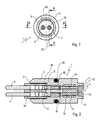
- Figure 1 is a view of the underside of an initiator according to the invention in which the conductive clamps are separate parts of the electrodes.
- FIG. 2 is a section on BB of the initiator shown in FIG. 1.
- FIG. 3 is a section along AA of the initiator shown in FIG. 1.
- FIG. 4 is a perspective view of a conductive clamp used for producing the initiator shown in FIGS. 1 to 3.
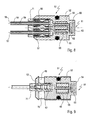
- Figures 5 and 6 illustrate, seen in section respectively along BB. and AA, the method of assembling the conductive wires, the closure ring and the conductive clips in the initiator shown in FIGS. 1 to 3.
- FIG. 7 is a view of the underside of an initiator according to the invention in which the conductive clips and the electrodes form single pieces.
- FIG. 8 is a section along DD of the initiator shown in FIG. 7.
- FIG. 9 is a section along CC of the initiator shown in FIG. 7.
- FIGS. 10 and 11 illustrate, seen in section respectively along DD and CC, the method of assembling the conducting wires and the closure ring in the initiator shown in FIGS. 7 and 9.
- FIG. 12 represents, seen in section, a pyrotechnic gas generator for an airbag intended for the driver of a motor vehicle and equipped with an initiator as shown in FIGS. 7 to 9.
- FIG. 13 represents, seen in section, a pyrotechnic gas generator for a seat belt retractor equipped with an initiator as shown in FIGS. 7 and 9.
- a two-wire initiator 1 comprises a base 2 of revolution, of general cylindrical shape, the ends of which are constituted by two flat faces 3 and 4.
- the base 2 is consisting of an insulating material against the current electrical, for example plastic or ceramic coated with plastic and has a seal sealing exterior 42 to allow its introduction into a gas generator.
- the base 2 has a first central bore 5 of revolution leading to the flat face 3.
- bore 5 will be qualified “lower”, side 3 will be called “lower”.
- In the bore 5 penetrate two conductive wires of electricity 6 and 7 each consisting of a core 8 electrically conductive surrounded by a sheath insulating 9.
- the base 2 has a second central bore 10 of revolution leading to side 4 opposite side 3.
- bore 10 will be qualified as "superior” and side 4 will be qualified as "superior”.
- the upper bore 10 contains a device pyrotechnic initiation 11 consisting of a wire resistant 12 covered with a pyrotechnic composition initiation 13.
- Two electrodes 14 and 15 are fixed inside of the base 2. As can be seen in Figures 2 and 3, the base 2 is molded on said electrodes. Advantageously the electrodes 14 and 15 are surrounded by a ferrite core 16.
- the upper ends of said electrodes are soldered to the resistant wire 12 of the initiation device pyrotechnics 11.
- each of the electrodes 14 and 15 is finished in its lower part by a conductive clamp 17 and 18 susceptible, under the constraint of a thrust exerted in the extension of said electrodes, to tighten one of the so-called conducting wires 6 or 7 by cutting its insulating sheath 9.
- the conductive clips 17 and 18 constitute parts separate from electrodes 14 and 15 and in progress assembly they are connected to these as it will be explained later in the description.
- the clamp 17 consists essentially of two rigid metal jumpers 19 and 20 in U shape arranged in the extension of one another.
- the side walls of the two jumpers 19 and 20 are interconnected by two deformable junctions 21 and 22 each consisting of two metal fasteners 23 and 24 in the form of opposite circular sectors.
- the clamp 17 appears as essentially constituted by two flat metal legs 25 and 26 arranged opposite one another, each leg comprising a deformable zone which coincides with the deformable junctions 21 and 22.
- the clamp 17 is extended by a socket 29 likely to enclose one of the electrodes 14 or 15.
- the inner part of the first bore 5 has two recesses in the form of radial grooves 32 and 33 diametrically opposite.
- the ends of the conducting wires 6 and 7 penetrating in the lower bore 5 of the base 2 are supported by a closing ring 34. It is essential, for reasons which will be explained later in the description, that this closure ring is made in a non-conductive plastic of electricity and having a certain elasticity.
- this closure ring 34 has on its external lateral wall two ribs 35 and 36 allowing in cooperation with the gorges 32 and 33 a irreversible snap-fastening of the ring 34 in the base 2.
- the ring 34 of generally cylindrical shape is crossed by two bores 37 and 38 in which penetrate each of the sheathed conducting wires 6 or 7.
- Each of the two bores 37 or 38 of the ring 34 includes a lower part whose dimensions minimum are substantially equal to the outside diameter sheathed conducting wires 6 or 7 and part upper whose dimensions allow the introduction of one of the conductive clips 17 or 18, the ring closure thus presenting in each of the bores a bottom 39 serving as rear stop for the clamps 17 or 18.
- each bore is extended inside the ring 34 by two tabs 40 and 41 whose spacing is substantially equal to the outside diameter of the sheathed wires 6 or 7, the bottoms 39 and the tabs 40 and 41 thus constituting clamping elements conductive 17 and 18 as it is going to be now Explain.
- the sockets 29 of the conductive clips 17 and 18 penetrate the narrow bores 30 and 31 and come in contact with electrodes 14 and 15 while the tabs of these clamps abut against the bottom of the bore 5 and that the conductive wires penetrate into the pliers to the internal stops 27 and 28.
- the conductive clips 17 and 18 have a length initial such that, under these conditions, the introduction ring 34 until it clicks into place requires a deformation of deformable junctions 21 and 22 by inward bending of the clip clamps 23 and 24 which enclose the wires conductors 6 and 7 by cutting their insulating sheath to come into contact with conductive souls as it is visible in Figure 3.
- the invention thus allows the implementation of a assembly process on a continuous chain of pyrotechnic gas generators equipped with wires conductors that the initiator, devoid of wires conductors and closure ring, is incorporated to the generator at the start of the assembly line and according to which the sheathed conducting wires supported by the closing ring possibly fitted with pliers are incorporated into the contained initiator in the generator that later this incorporation being irreversible, internal to the initiator and therefore to the generator and requiring no welding.
- FIGS. 7 to 11 show a variant of realization that the electrodes and the clamps conductive forms unique pieces.
- an initiator 51 comprising a base 52 whose ends are constituted by two flat faces 53 and 54.
- the base 52 has a lower bore 55 of revolution emerging on the lower flat face 53 and in which penetrate two conductive wires 56 and 57 each consisting of a conductive core 58 surrounded by an insulating sheath 59.
- the base 52 also has a second bore said upper 60 opening onto the other flat face 54 and containing a pyrotechnic initiation device 61 constituted by a resistant wire 62 and by a composition pyrotechnic 63.
- the base 52 is molded around two electrodes 64 and 65 surrounded by a ferrite core 66 and incorporating clips in their lower part conductors 67 and 68 similar to those described more high.
- the lower part of the first bore 55 has two radial grooves 69 and 70.
- the ends of the conductive wires 56 and 57 entering the bore 55 are supported by a ring closure 71 of insulating plastic material having some elasticity.
- the ring 71 is a piece of elliptical section revolution which presents two external ribs 72 and 73 allowing, in cooperation with radial grooves 69 and 70 a snap irreversible of the ring 71 in the base 52.
- the closing ring 71 is crossed by two cylindrical bores 74 and 75 each having a lower part whose diameter is substantially equal the outside diameter of the sheathed conducting wires 56 and 57 and an upper part whose diameter allows the introduction of one of the conductive clips 67 or 68, the closure ring thus presenting, in each bores 74 and 75 a bottom 76 and 77.
- each of the bores 74 and 75 is extended inside the ring 71 by a notched, cylindrical collar and hollow 78 and 79 whose internal diameter is substantially equal to the outside diameter of said wires sheathed 56 and 57.
- Funds 76 and 77 as well as scalloped collars 78 and 79 constitute the elements stressing conductive clips 67 and 68.
- base 52 carries an external seal 80 to allow its use in a gas pyrotechnic generator.
- FIG. 12 An example is shown in FIG. 12 using an initiator as described and illustrated in Figures 7 to 9 in a pyrotechnic generator gas 100 for airbag.
- the generator shown in this figure is described in detail in the French patent application No. 2,730,965 and is more particularly intended for be housed in the steering wheel of a motor vehicle to protect its driver.
- the generator 100 comprises a cylindrical body 102 closed by a metallic ring 103 set in this latest.
- the metal ring 103 includes an orifice in which the initiator 101 is housed according to the invention which, in this example, is reinforced by a 104 live powder contained in a metal cap fragmentable 105 arranged around the initiator 101.
- the powder 104 is advantageously a powder based on boron and potassium nitrate.
- a hollow cylindrical block 106 of composition pyrotechnic gas generator is arranged around the ignition device thus formed.
- the composition gas generator is advantageously constituted by a composite propellant with silicone binder and whose charge oxidant is based on ammonium perchlorate and sodium nitrate.
- Block 106 is wedged by a spring 107 and by a metallic wedging piece 108.
- ports 109 allow combustion gases to exit the body 102 of the generator which carries an annular ring external 110 supporting an openwork deflector 111 thus than a diffuser 112.
- the gases leaving the body of the generator by the orifices 109 are distributed by the perforated deflector 111 on condensing grids 113 and 114 before leaving the generator with a peripheral circular opening 115 for inflating the protective cushion.
- Screws 116 carried by the ring external 110 allow the generator 100 to be fixed in the steering wheel.
- the generator 100 can be easily assembled on an assembly line continues from the initiator 101 devoid of its conducting wires 117 and 118 as well that of its closure ring 119 which are not place that at the end of the assembly line on the generator fully assembled or even that will only be put in place only later on the module incorporating this generator.
- FIG. 13 An example is shown in FIG. 13 of using an initiator 151 as described and illustrated by figures 7 to 9 in a generator gas pyrotechnic 150 for belt retractor security.
- the generator 150 consists of a metal body cylindrical 152 with a fragmentable cap 153 due to an increase in internal pressure to the generator.
- the generator 150 contains an initiator 151 according to the invention as well as a generating powder of gas 154.
- the body 152 of the generator is crimped onto the base 155 of the initiator 151.
- the generator 150 can also be easily assembled on a continuous assembly line from the initiator 151 devoid of its conducting wires 156 and 157 as well as its closure ring 158 which are put in place on the fully assembled generator, either end of the assembly line, or later, in the seat belt retractor modules already assembled and incorporating the generator 150.
Landscapes
- Engineering & Computer Science (AREA)
- General Engineering & Computer Science (AREA)
- Mechanical Engineering (AREA)
- Air Bags (AREA)
- Automotive Seat Belt Assembly (AREA)
Claims (15)
- Pyrotechnischer Zweileiter-Zünder (1), der insbesondere aufweist:i) eine Basis (2), deren Enden zwei ebene Flächen (3, 4) bilden, wobei die Basis eine erste, "untere" genannte zentrale Bohrung (5) aufweist, die in der einen der Flächen endet und durch welche zwei elektrisch leitfähige Leiter (6, 7) verlaufen, die jeweils aus einer leitfähigen Seele (8) bestehen, die von einer isolierenden Hülle (9) umgeben ist, sowie eine zweite, "obere" genannte zentrale Bohrung (10), die von der ersten Bohrung beabstandet ist und die in der anderen ebenen Fläche (4) mündet und die eine pyrotechnische Zündervorrichtung (11) umfasst,ii) zwei Elektroden (14, 15), die innen an der Basis fixiert sind und deren Enden sich jeweils in den zwei Bohrungen (5, 10) befinden, wobei die unteren Enden jeder Elektrode mit dem einen der leitfähigen Leiter verbunden sind, während die oberen Enden der Elektroden mit der pyrotechnischen Zündvorrichtung (11) verbunden sind,
dadurch gekennzeichnet, dass:iii) jede der Elektroden (14, 15) an ihrem unteren Teil in einer leitfähigen Klemme (17, 18) endet, die durch Einwirken eines Schubs, der in der Verlängerung der Elektroden wirkt, einen der leitfähigen Leiter (6, 7) greift, indem in seine isolierende Hülle (9) geschnitten wird,IV) der untere Teil der ersten zentralen Bohrung (5) wenigstens eine Aussparung aufweist,V) die Enden der leitfähigen Leiter (6, 7), die durch die erste zentrale Bohrung (5) der Basis (2) verlaufen, durch einen Verschlussring (34) getragen werden, dessen Seitenband wenigstens eine externe Rippe (35, 36) aufweist, die in Zusammenwirkung mit der Aussparung (32, 33) ein irreversibles Einklinken des Rings (34) in die Basis (2) ermöglicht, wobei der Ring im übrigen Elemente umfasst, um auf die leitfähigen Klemmen (17, 18) einzuwirken. - Pyrotechnischer Zünder nach Anspruch 1, dadurch gekennzeichnet, dass die erste zentrale Bohrung (5) zwei Auskehlungen (32, 33) aufweist.
- Pyrotechnischer Zünder nach Anspruch 2, dadurch gekennzeichnet, dass die Basis (2) eine rotationsförmige Basis ist, deren Enden aus zwei ebenen Flächen (3, 4) bestehen, und dass die erste Bohrung (5) und die zweite Bohrung (10) rotationsförmige Bohrungen sind.
- Pyrotechnischer Zünder nach Anspruch 3, dadurch gekennzeichnet, dass jede leitfähige Klemme (17) im wesentlichen aus zwei ebenen metallischen Klammern (25, 26) besteht, die einander gegenüber angeordnet sind, wobei jede Klammer einen deformierbaren Bereich (21, 22) aufweist, der aus zwei Metalllaschen (23, 24) in Form von Kreissegmenten besteht.
- Pyrotechnischer Zünder nach Anspruch 4, dadurch gekennzeichnet, dass der Verschlussring (71) durchbrochen wird durch zwei zylindrische Bohrungen (74, 75), durch welche jeweils die umhüllten leitfähigen Leiter verlaufen.
- Pyrotechnischer Zünder nach Anspruch 5, dadurch gekennzeichnet, dass der Verschlussring (71) zwei zylindrische Bohrungen (74, 75) aufweist, die einen unteren Abschnitt aufweisen, dessen Durchmesser im wesentlichen gleich dem äusseren Durchmesser der umhüllten leitfähigen Leiter ist, und einen oberen Abschnitt, dessen Durchmesser die Einführung der einen der leitfähigen Klammern (67, 68) ermöglicht, wobei der Verschlussring ausserdem bei jeder der Bohrungen (74, 75) einen Boden (76, 77) aufweist.
- Pyrotechnischer Zünder nach Anspruch 6, dadurch genkennzeichnet, dass der untere Abschnitt jeder Bohrung in den Ring (71) durch einen zylindrischen Hohlkragen (78, 79) verlängert wird, dessen Innendurchmesser im wesentlichen gleich dem Aussendurchmesser der umhüllten Leiter ist, wobei die Böden (76, 77) und die Krägen (78, 79) die Elemente darstellen, die auf die leitfähigen Klammern einwirken.
- Pyrotechnischer Zünder nach Anspruch 7, dadurch gekennzeichnet, dass die Basis (2) mit den Elektroden (14, 15) vergossen wird.
- Pyrotechnischer Zünder nach Anspruch 8, dadurch gekennzeichnet, dass die Zündvorrichtung aus einem Widerstand (12), der an den Elektroden befestigt ist, und einer pyrotechnischen Zündmischung (13) gebildet wird.
- Pyrotechnischer Zünder nach Anspruch 9, dadurch gekennzeichnet, dass die pyrotechnische Zündmischung aus einem mit einem Lack auf Basis von Nitrocellulose vermischten Zündpulver besteht.
- Pyrotechnischer Zünder nach einem der Ansprüche 1 bis 10, dadurch gekennzeichnet, dass die Elektroden (14, 15) wenigstens von einem Ferritkern (16) umgeben sind.
- Verwendung eines pyrotechnischen Zünders nach einem der Ansprüche 1 bis 11 in einem pyrotechnischen Gasgenerator für Fahrzeugsicherheitseinrichtungen.
- Verwendung nach Anspruch 12, dadurch gekennzeichnet, dass der pyrotechnische Gasgenerator zum Aufblasen eines Schutzkissens für Insassen eines Fahrzeugs dient.
- Verwendung nach Anspruch 12, dadurch gekennzeichnet, dass der pyrotechnische Gasgenerator zum Treiben eines Gurtstraffers von Fahrzeuginsassen dient.
- Verfahren zum Zusammenbauen eines pyrotechnischen Gasgenerators mit einem pyrotechnischen Zünder nach einem der Ansprüche 1 bis 11 in der Fertigung, dadurch gekennzeichnet, dass der Zünder ohne leitfähige Leiter und Verschlussring in den Generator am Anfang der Fertigung für das Zusammenbauen eingesetzt wird und dass die leitfähigen, umhüllten und durch den Verschlussring getragenen Leiter erst am Schluss eingesetzt werden.
Applications Claiming Priority (2)
| Application Number | Priority Date | Filing Date | Title |
|---|---|---|---|
| FR9604995 | 1996-04-22 | ||
| FR9604995A FR2747772B1 (fr) | 1996-04-22 | 1996-04-22 | Initiateur a prise bifilaire autobloquante pour generateurs pyrotechniques de gaz |
Publications (2)
| Publication Number | Publication Date |
|---|---|
| EP0803700A1 EP0803700A1 (de) | 1997-10-29 |
| EP0803700B1 true EP0803700B1 (de) | 2001-11-14 |
Family
ID=9491423
Family Applications (1)
| Application Number | Title | Priority Date | Filing Date |
|---|---|---|---|
| EP97400828A Expired - Lifetime EP0803700B1 (de) | 1996-04-22 | 1997-04-11 | Zünder mit selbstklemmendem Zweileiter-Anschluss für pyrotechnische Gasgeneratoren |
Country Status (5)
| Country | Link |
|---|---|
| US (1) | US6146598A (de) |
| EP (1) | EP0803700B1 (de) |
| JP (1) | JP2905758B2 (de) |
| DE (1) | DE69708196T2 (de) |
| FR (1) | FR2747772B1 (de) |
Families Citing this family (20)
| Publication number | Priority date | Publication date | Assignee | Title |
|---|---|---|---|---|
| FR2788846B1 (fr) | 1999-01-25 | 2001-10-26 | Livbag Snc | Generateur de gaz hybride muni d'un initiateur a chargement explosif profile |
| US6644198B1 (en) * | 2000-10-31 | 2003-11-11 | Special Devices, Inc. | Integral pyrotechnic initiator with molded connector |
| ATE374709T1 (de) * | 2001-04-03 | 2007-10-15 | Nknm Ltd | Als einheit ausgeführter kopfstück/basis/kurzschlussbrücken-halter für einen mikrogasgenerator und diesen verwendender mikrogasgenerator |
| JP2003249308A (ja) * | 2002-02-25 | 2003-09-05 | Tyco Electronics Amp Kk | 電気コネクタ組立体 |
| EP1511659B1 (de) * | 2002-06-07 | 2005-10-26 | Autoliv Development Ab | Elektrisch isolierte befestigungsanordnung für ein airbagmodul |
| DE10225384C1 (de) * | 2002-06-07 | 2003-11-27 | Guenter Duerschinger | Zündvorrichtung für den Gasgenerator eines Insassen-Rückhaltesystems in einem Kraftfahrzeug |
| FR2843191B1 (fr) * | 2002-08-01 | 2006-12-29 | Delta Caps Internat Dci | Installation de tirs pyrotechniques et detonateur pour une telle installation |
| US6877431B2 (en) * | 2002-10-21 | 2005-04-12 | Schott Glas | Hermetically sealed electrical feed-through device with a bent isolated pin in a circular glass seal |
| US6874423B2 (en) * | 2002-10-21 | 2005-04-05 | Schott Glas | Hermetically sealed electrical feed-through device with a straight isolated pin in an offset oval glass seal |
| US7077428B2 (en) | 2003-07-07 | 2006-07-18 | Autoliv Asp, Inc. | Airbag initiator cover attachment apparatus and method |
| US7401810B2 (en) * | 2003-07-07 | 2008-07-22 | Autoliv Asp, Inc. | Ultrasonic welded initiator and connector socket |
| US7510211B2 (en) * | 2003-12-11 | 2009-03-31 | Autoliv Asp, Inc. | Snap-locking initiator assemblies for inflator devices |
| US7192054B2 (en) * | 2003-12-11 | 2007-03-20 | Autoliv Asp, Inc. | Locking initiator assembly for an airbag inflator device |
| CA2558287C (en) * | 2004-03-18 | 2011-06-07 | Orica Explosives Technology Pty Ltd | Connector for electronic detonators |
| FR2874686B1 (fr) | 2004-08-27 | 2006-10-27 | Livbag Soc Par Actions Simplif | Corps d'initiateur a joint moule, initiateur et generateur qui en sont pourvus, et un procede de fabrication |
| DE102006002209B3 (de) * | 2006-01-16 | 2007-08-02 | Stabilus Gmbh | Aktuator |
| PE20130052A1 (es) | 2009-11-03 | 2013-02-04 | Orica Explosives Tech Pty Ltd | Conector |
| US8863665B2 (en) | 2012-01-11 | 2014-10-21 | Alliant Techsystems Inc. | Connectors for separable firing unit assemblies, separable firing unit assemblies, and related methods |
| US9050944B1 (en) * | 2012-11-30 | 2015-06-09 | Tk Holdings Inc. | Gas generating system with initiator sub-assembly |
| KR101987170B1 (ko) * | 2017-10-18 | 2019-06-10 | 주식회사 풍산 | 포 발사 적용을 위한 점화보조물질이 도포된 램제트 고체연료 |
Family Cites Families (10)
| Publication number | Priority date | Publication date | Assignee | Title |
|---|---|---|---|---|
| DE3376242D1 (en) * | 1982-07-23 | 1988-05-11 | Molex Inc | Insulation displacement terminal for an electrical connector and environmental sealing means therefor |
| US5431440A (en) * | 1990-08-23 | 1995-07-11 | Deutsche Aerospace Ag | Restraint system for passengers in vehicles with opto-electric trigger means |
| EP0474113B1 (de) * | 1990-09-01 | 1995-09-20 | Molex Incorporated | Verbindungsvorrichtung für Mehrleiterkabel |
| US5200574A (en) * | 1991-04-05 | 1993-04-06 | Morton International, Inc. | Universal squib connector |
| DE4140692A1 (de) * | 1991-12-10 | 1993-06-17 | Trw Repa Gmbh | Elektrische steckverbindung an einem mit elektrischem zuender versehenen pyrotechnischen gasgenerator |
| US5404263A (en) * | 1992-08-27 | 1995-04-04 | Oea, Inc. | All-glass header assembly used in an inflator system |
| EP0598940B1 (de) * | 1992-11-26 | 1995-11-08 | Molex Incorporated | Elektrische Verbinderanordnung mit Isolierungsverdrängung |
| DE4307774A1 (de) * | 1993-03-12 | 1994-09-15 | Dynamit Nobel Ag | Anzündeinrichtung |
| JP2700100B2 (ja) * | 1993-05-28 | 1998-01-19 | 日本工機株式会社 | イグナイター |
| US5660413A (en) * | 1995-08-24 | 1997-08-26 | Trw Vehicle Safety Systems Inc. | Air bag inflator with laser diode initiator |
-
1996
- 1996-04-22 FR FR9604995A patent/FR2747772B1/fr not_active Expired - Fee Related
-
1997
- 1997-04-11 EP EP97400828A patent/EP0803700B1/de not_active Expired - Lifetime
- 1997-04-11 DE DE69708196T patent/DE69708196T2/de not_active Expired - Lifetime
- 1997-04-21 JP JP9103268A patent/JP2905758B2/ja not_active Expired - Lifetime
-
1999
- 1999-02-18 US US09/252,861 patent/US6146598A/en not_active Expired - Fee Related
Also Published As
| Publication number | Publication date |
|---|---|
| JP2905758B2 (ja) | 1999-06-14 |
| JPH10114257A (ja) | 1998-05-06 |
| EP0803700A1 (de) | 1997-10-29 |
| DE69708196D1 (de) | 2001-12-20 |
| US6146598A (en) | 2000-11-14 |
| DE69708196T2 (de) | 2002-07-04 |
| FR2747772B1 (fr) | 1999-08-06 |
| FR2747772A1 (fr) | 1997-10-24 |
Similar Documents
| Publication | Publication Date | Title |
|---|---|---|
| EP0834716B1 (de) | Pyrotechnischer Mikrogasgenerator mit zweiadriger festgehaltener Dose | |
| EP0803700A1 (de) | Zünder mit selbstklemmendem Zweileiter-Anschluss für pyrotechnische Gasgeneratoren | |
| EP0849131B1 (de) | Pyrotechnischer rohrförmiger integraler Gasgenerator für Airbags | |
| EP0728634B1 (de) | Pyrotechnischer Aufblaser für einen Kraftfahrzeug-Gassack | |
| FR2742109A1 (fr) | Dispositif pour declencher un gonfleur d'un organe de retenue d'un occupant d'un vehicule | |
| EP1030159B1 (de) | Elektropyrotechnischer Zünder mit erhöhter Zündsicherheit | |
| EP0879739B1 (de) | Adaptativer, pyrotechnischer Gasgenerator mit rohrförmigen Kammern für einen Airbag | |
| US5433147A (en) | Ignition device | |
| CA2217399C (fr) | Initiateur electropyrotechnique, procede de realisation d'un tel initiateur et systeme de securite pour vehicule | |
| EP0757026B1 (de) | Heisses Gas-erzeugender pyrotechnischer Gasgenerator für Seitenaufprallschutz-Airbag | |
| FR2759958A1 (fr) | Dispositif de gonflage hybride pour airbags | |
| FR2788846A1 (fr) | Generateur de gaz hybride muni d'un initiateur a chargement explosif profile | |
| FR2557689A1 (fr) | Initiateur pyrotechnique utilisant une prise coaxiale | |
| EP1046552B1 (de) | Schutzeinheit mit einem äusseren, expandierbaren Deflektor | |
| FR2999129A1 (fr) | Ensemble actionneur pyrotechnique et module de coussin de securite gonflable equipe de celui-ci | |
| FR2809693A1 (fr) | Generateur hybride a pilier perforateur et a corps bi-tubulaire | |
| EP1086862A1 (de) | Aufblasbare, metallische Struktur mit integrierter, pyrotechnischer Ladung | |
| EP0849130B1 (de) | Pyrotechnischer Gasgenerator mit Verbundladung | |
| FR2772909A1 (fr) | Initiateur electro-pyrotechnique a trois connexions electriques | |
| FR2984253A1 (fr) | Generateur ou micro-generateur de gaz pour un dispositif de securite pour vehicule automobile. | |
| CA2404836C (fr) | Generateur de gaz hybride pour coussin gonflable de protection laterale applique a la securite automobile | |
| EP1112470A1 (de) | Pyrotechnischer zünder und verfahren zur montage eines derartigen zünders | |
| EP1139060B1 (de) | Pyrotechnischer Zünder mit einem elektrischen oder elektronischen Bauelement und/oder mit einem Steckverbinder | |
| CN114341589B (zh) | 烟火点火爆管及烟火点火爆管的制造方法 | |
| EP3390956B1 (de) | Gasgenerator |
Legal Events
| Date | Code | Title | Description |
|---|---|---|---|
| PUAI | Public reference made under article 153(3) epc to a published international application that has entered the european phase |
Free format text: ORIGINAL CODE: 0009012 |
|
| AK | Designated contracting states |
Kind code of ref document: A1 Designated state(s): DE FR |
|
| 17P | Request for examination filed |
Effective date: 19980429 |
|
| GRAG | Despatch of communication of intention to grant |
Free format text: ORIGINAL CODE: EPIDOS AGRA |
|
| GRAH | Despatch of communication of intention to grant a patent |
Free format text: ORIGINAL CODE: EPIDOS IGRA |
|
| 17Q | First examination report despatched |
Effective date: 20010419 |
|
| GRAH | Despatch of communication of intention to grant a patent |
Free format text: ORIGINAL CODE: EPIDOS IGRA |
|
| GRAA | (expected) grant |
Free format text: ORIGINAL CODE: 0009210 |
|
| AK | Designated contracting states |
Kind code of ref document: B1 Designated state(s): DE FR |
|
| REF | Corresponds to: |
Ref document number: 69708196 Country of ref document: DE Date of ref document: 20011220 |
|
| PLBE | No opposition filed within time limit |
Free format text: ORIGINAL CODE: 0009261 |
|
| STAA | Information on the status of an ep patent application or granted ep patent |
Free format text: STATUS: NO OPPOSITION FILED WITHIN TIME LIMIT |
|
| 26N | No opposition filed | ||
| REG | Reference to a national code |
Ref country code: FR Ref legal event code: TP |
|
| PGFP | Annual fee paid to national office [announced via postgrant information from national office to epo] |
Ref country code: FR Payment date: 20120223 Year of fee payment: 16 |
|
| PGFP | Annual fee paid to national office [announced via postgrant information from national office to epo] |
Ref country code: DE Payment date: 20120208 Year of fee payment: 16 |
|
| PG25 | Lapsed in a contracting state [announced via postgrant information from national office to epo] |
Ref country code: DE Free format text: LAPSE BECAUSE OF NON-PAYMENT OF DUE FEES Effective date: 20131101 |
|
| REG | Reference to a national code |
Ref country code: FR Ref legal event code: ST Effective date: 20131231 |
|
| REG | Reference to a national code |
Ref country code: DE Ref legal event code: R119 Ref document number: 69708196 Country of ref document: DE Effective date: 20131101 |
|
| PG25 | Lapsed in a contracting state [announced via postgrant information from national office to epo] |
Ref country code: FR Free format text: LAPSE BECAUSE OF NON-PAYMENT OF DUE FEES Effective date: 20130430 |