EP0803714A2 - Système de surveillance du niveau de remplissage - Google Patents
Système de surveillance du niveau de remplissage Download PDFInfo
- Publication number
- EP0803714A2 EP0803714A2 EP97103474A EP97103474A EP0803714A2 EP 0803714 A2 EP0803714 A2 EP 0803714A2 EP 97103474 A EP97103474 A EP 97103474A EP 97103474 A EP97103474 A EP 97103474A EP 0803714 A2 EP0803714 A2 EP 0803714A2
- Authority
- EP
- European Patent Office
- Prior art keywords
- monitoring system
- level monitoring
- evaluation circuit
- strain gauge
- microprocessor
- Prior art date
- Legal status (The legal status is an assumption and is not a legal conclusion. Google has not performed a legal analysis and makes no representation as to the accuracy of the status listed.)
- Ceased
Links
Images

Classifications
-
- G—PHYSICS
- G01—MEASURING; TESTING
- G01G—WEIGHING
- G01G3/00—Weighing apparatus characterised by the use of elastically-deformable members, e.g. spring balances
- G01G3/12—Weighing apparatus characterised by the use of elastically-deformable members, e.g. spring balances wherein the weighing element is in the form of a solid body stressed by pressure or tension during weighing
-
- G—PHYSICS
- G01—MEASURING; TESTING
- G01G—WEIGHING
- G01G21/00—Details of weighing apparatus
- G01G21/23—Support or suspension of weighing platforms
Definitions
- the present invention relates to a fill level monitoring system for containers, in particular silos, according to the preamble of patent claim 1.
- Level monitoring is carried out in silos in order to balance the material stored or removed.
- the semiconductor strain gauges produce very accurate analog output signals, but are also very expensive. As a rule, several strain gauges are required to measure the fill level of a silo more precisely. Usually, the output signals of the strain gauges are transmitted over a longer distance to a central amplification and evaluation device and, if necessary, processed and displayed. During the transmission of the output signals of the strain gauges, however, electromagnetic interference signals can easily be looped into the measuring system, which falsify the measurement results.
- the evaluation circuit according to the invention Due to the arrangement of the evaluation circuit according to the invention in the immediate vicinity of the strain gauge on the measuring foot and the direct digitization and storage of the measured values prior to transmission over a longer distance, the system is insensitive to interference signals.
- the evaluation circuit constructed according to the invention enables the use of strain gauges, which cost a fraction of the expensive semiconductor strain gauges, without the accuracy of the measurement being impaired thereby. After digitization has taken place, the measured value is possible with easily controllable transmission techniques via standardized data bus systems to a central computer, as a result of which the monitoring system can be easily integrated into the overall control of a silo system.
- the evaluation circuit comprises a microprocessor which controls the operation of the analog / digital converter and the memory.
- This decentralized control eliminates the need to transmit command signals for the operation of the evaluation circuit over long distances from a central computer to the evaluation circuit. In a system with multiple silos in particular, this considerably simplifies the outlay for hardware and software.
- the evaluation circuit preferably comprises an amplifier which can be adjusted with regard to its amplification and its zero point, as a result of which the system can be used universally for different types of silos and under variable operating conditions.
- the setting of the amplifier and the zero point can preferably be controlled by the microprocessor, from which the possibility arises of transmitting configuration commands under software control to the microprocessor from a central computer, which considerably simplifies the adjustment of the evaluation circuit during operation.
- the system comprises a temperature sensor, the output signal of which is used by the microprocessor to set the zero point of the amplifier in order to achieve automatic temperature compensation.
- the fill level monitoring system comprises a superordinate control computer which can read out the memory of the evaluation circuit in order to manage the measured values centrally.
- the system preferably has devices which are used to process the measured value signal of the evaluation circuit in order to bring it into a form suitable for transmission to the control computer.
- the evaluation circuit is mounted in a housing and the housing is placed directly on the strain gauge.
- the housing has a bottom opening which corresponds approximately to the dimensions of the strain gauge.
- the electrical connection paths extremely short between strain gauges.
- the housing can have electrical shielding means in order to prevent the radiation of electromagnetic interference signals.
- the bottom opening and the strain gauge are preferably filled with a silicone sealing compound in order to protect the electrical measuring and evaluation circuit from moisture.
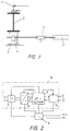
- FIG. 1 shows an overview of the structure of the level monitoring system according to the invention.
- the silo container is only shown schematically by an outer wall 1.
- the arrow in the drawing should symbolize the diameter of the container.
- the silo is supported at its lower end by a ring support 2, which is itself supported on a measuring foot 3, which stands on a foundation, possibly anchored there.
- the measuring foot consists of an I-shaped carrier, on the middle wall of which the strain gauge (DMS) is attached approximately in the middle, preferably glued.
- DMS strain gauge
- the housing 4 of the evaluation circuit is attached to the carrier.
- the housing has an opening in the bottom that is roughly the size of the strain gauge.
- the housing is preferably attached to the carrier by screwing or gluing. Then the bottom opening and the strain gage are poured out with a silicone compound to protect it from the weather, especially moisture.
- a number of evaluation circuits can be connected to a central control computer 5, it being ensured by means of a level converter 6 that bus signals are brought into a format which is accepted by the central control computer.
- the central control computer is a commercially available PC with an Intel 80X86 processor, which communicates via an RS232 serial interface with the level converter 6, which converts the RS232 level to the RS422 level. In this format, control signals can also be transmitted over longer distances.
- the level converter 6 comprises a laser diode for converting the electrical control signals into suitable photoelectric pulses.
- the transmission losses are extremely small and the sensitivity to interference of the transmission system is very low.
- the evaluation circuit 7 is a voltage supply circuit 8 fed, which regulates a DC voltage of + 24V down to a suitable supply voltage level, for example + 5V.
- the evaluation circuit 7 comprises a microprocessor with an erasable read-only memory 9 (EEPROM), as well as an analog / digital (A / D) converter 11, a bus interface 10 and an amplifier 12.
- the microprocessor 9 controls the bus interface 10 for exchange during operation of the evaluation circuit of measurement data.
- the data can be temporarily stored in the bus interface, for example, and can be transmitted to the control computer 5 upon a request signal.
- the bus interface receives command signals from the control computer, which are directed to the microprocessor.
- this data is configuration data for setting the gain factor and the zero point of the amplifier.
- the A / D converter 11 used is a commercially available converter which provides a 10-bit digital signal at its output which is read by the microprocessor.
- the A / D converter can be set with regard to its parameters, for example its speed.
- the output signal of the A / D converter is either provided in response to a request signal from the microprocessor or the microprocessor queries the output of the converter cyclically.
- the microprocessor stores the measured values obtained from the converter in its internal memory.
- Fig. 3 the connection of the amplifier 12 to a strain gauge is shown, which is designed as a full bridge.
- a suitable strain gauge is, for example, the type J2A-06-S1425-35B from Masurements Group.
- the bridge receives the at a connection V DMS Bridge supply voltage with respect to a ground potential GND and generates a bridge output voltage at the two output terminals.
- the two output terminals are connected to the input of a preamplifier v1 of the amplifier 12.
- the pre-amplified output signal receives an offset from an adjustable resistor.
- the offset voltage can be set by the microprocessor in a range from -V DMS to + V DMS .
- the preamplified and offset-compensated measurement signal is amplified by a further amplifier v2, the amplification factor of the amplifier v2 being adjustable via the microprocessor.
- the measurement signal thus prepared is then fed to the A / D converter 11 in order to digitize it.
- the bridge output voltage of the strain gauge 13 is amplified in a suitable manner by the amplifier 12 in order to provide a measurement signal for the analog / digital converter.
- the microprocessor polls the digital output of the A / D converter cyclically and stores the current value in its internal memory. When the microprocessor receives a request signal from the control computer 5, it transfers a measured value to the bus interface. From there, the data can be transmitted to the level converter 6 and, after suitable conversion, read in, processed and displayed by the control computer.
- the fill level monitoring system according to the present invention is not limited to the designs with only one strain gauge and an electrical evaluation circuit. Rather, it is possible to use a large number of strain gauges and associated evaluation circuits, each of which has a measuring foot is arranged to operate under central control of the control computer, as indicated in Fig. 1. In this case, a specific address can be assigned to each microprocessor in order to selectively address and query the evaluation circuits.
Landscapes
- Physics & Mathematics (AREA)
- General Physics & Mathematics (AREA)
- Arrangements For Transmission Of Measured Signals (AREA)
- Measurement Of Levels Of Liquids Or Fluent Solid Materials (AREA)
Applications Claiming Priority (2)
| Application Number | Priority Date | Filing Date | Title |
|---|---|---|---|
| DE1996116192 DE19616192A1 (de) | 1996-04-23 | 1996-04-23 | Füllstandsüberwachungssystem |
| DE19616192 | 1996-04-23 |
Publications (2)
| Publication Number | Publication Date |
|---|---|
| EP0803714A2 true EP0803714A2 (fr) | 1997-10-29 |
| EP0803714A3 EP0803714A3 (fr) | 1998-10-07 |
Family
ID=7792202
Family Applications (1)
| Application Number | Title | Priority Date | Filing Date |
|---|---|---|---|
| EP97103474A Ceased EP0803714A3 (fr) | 1996-04-23 | 1997-03-03 | Système de surveillance du niveau de remplissage |
Country Status (2)
| Country | Link |
|---|---|
| EP (1) | EP0803714A3 (fr) |
| DE (1) | DE19616192A1 (fr) |
Cited By (2)
| Publication number | Priority date | Publication date | Assignee | Title |
|---|---|---|---|---|
| US11358785B2 (en) | 2018-04-04 | 2022-06-14 | Superior Bulk, Inc. | Silo system and bulk material management system |
| US12045764B2 (en) | 2018-04-04 | 2024-07-23 | Superior Bulk, Inc. | Automated dispatch and delivery confirmation |
Families Citing this family (2)
| Publication number | Priority date | Publication date | Assignee | Title |
|---|---|---|---|---|
| DE29719163U1 (de) | 1997-10-29 | 1998-02-19 | Fischer Gase GmbH, 74927 Eschelbronn | Meßvorrichtung für Löschwasserleitungen |
| DE10046102A1 (de) * | 2000-09-18 | 2002-03-28 | Hbm Waegetechnik Gmbh | Wägevorrichtung zur Füllstandsmessung an Behältern |
Family Cites Families (4)
| Publication number | Priority date | Publication date | Assignee | Title |
|---|---|---|---|---|
| US2980414A (en) * | 1956-03-16 | 1961-04-18 | Cherry Burrell Corp | Compression bracket |
| US3981195A (en) * | 1975-07-21 | 1976-09-21 | Forney Engineering Company | Silo level measuring system |
| AT383678B (de) * | 1984-08-27 | 1987-08-10 | Leo Boehm Ges M B H | Vorrichtung zum abwiegen von auf mehreren beinen od.dgl. abgestuetzten behaeltern |
| DE3436287A1 (de) * | 1984-10-03 | 1986-04-10 | Zeppelin-Metallwerke Gmbh, 7990 Friedrichshafen | Vorrichtung zur fuellstandsmessung |
-
1996
- 1996-04-23 DE DE1996116192 patent/DE19616192A1/de not_active Withdrawn
-
1997
- 1997-03-03 EP EP97103474A patent/EP0803714A3/fr not_active Ceased
Cited By (2)
| Publication number | Priority date | Publication date | Assignee | Title |
|---|---|---|---|---|
| US11358785B2 (en) | 2018-04-04 | 2022-06-14 | Superior Bulk, Inc. | Silo system and bulk material management system |
| US12045764B2 (en) | 2018-04-04 | 2024-07-23 | Superior Bulk, Inc. | Automated dispatch and delivery confirmation |
Also Published As
| Publication number | Publication date |
|---|---|
| EP0803714A3 (fr) | 1998-10-07 |
| DE19616192A1 (de) | 1997-10-30 |
Similar Documents
| Publication | Publication Date | Title |
|---|---|---|
| DE19548390B4 (de) | Vorrichtung zum Messen von Fahrzeugbelastungen | |
| EP2087319B1 (fr) | Dispositif présentant un circuit transducteur à structure modulaire | |
| EP0169414A2 (fr) | Méthode pour la compensation en température et montage de mesure pour cette méthode | |
| DE2225153B2 (de) | Warneinrichtung zur Erzeugung eines Warnsignales bei fehlerhaftem Zustand eines Kranes | |
| DE3228559A1 (de) | Belastungsueberwachungssystem | |
| DE3151743A1 (de) | Messgeraet mit vielelementenfuehler | |
| EP0221251A1 (fr) | Méthode pour compenser des erreurs d'un capteur à caractéristique non linéaire et dispositif pour sa mise en oeuvre | |
| DE20213102U1 (de) | Vorrichtung zum Überwachen von Werkzeugen | |
| DE3111318A1 (de) | Verfahren zur bestimmung des zugwiderstandes und/oder der gasdurchlaessigkeit eines prueflings sowie einrichtung zur durchfuehrung eines solchen verfahrens | |
| DE3544095C2 (fr) | ||
| DD153734A5 (de) | Verfahren zur leckagemessung | |
| EP2534457A1 (fr) | Procédé et dispositif d'étalonnage automatique de capteurs d'allongement ou de force | |
| WO2003078937A1 (fr) | Cellule de mesure de force modulaire pour une balance | |
| WO1989003023A1 (fr) | Balance et procede d'etalonnage et d'utilisation de la balance | |
| DE2626023C3 (de) | Wiegevorrichtung | |
| DE3719532A1 (de) | Kraftmesseinrichtung | |
| EP0392080A1 (fr) | Procédé d'évaluation des signaux d'un gyromètre à fibre optique | |
| CH671101A5 (fr) | ||
| DE19616192A1 (de) | Füllstandsüberwachungssystem | |
| DE3545366C2 (fr) | ||
| DE102022122499A1 (de) | Radiometrische Füllstandsmessung | |
| DE102009023515B4 (de) | Verfahren und Vorrichtung zur Ermittlung des Feinpositionwertes eines zu überwachenden Körpers | |
| EP1850096A1 (fr) | Télétransmetteur pour appareils de mesure analogiques | |
| EP0093183A1 (fr) | Balance | |
| DE19648241C2 (de) | Meßverfahren zur Bestimmung von Massen |
Legal Events
| Date | Code | Title | Description |
|---|---|---|---|
| PUAI | Public reference made under article 153(3) epc to a published international application that has entered the european phase |
Free format text: ORIGINAL CODE: 0009012 |
|
| AK | Designated contracting states |
Kind code of ref document: A2 Designated state(s): AT BE CH DE FR IT LI NL |
|
| PUAL | Search report despatched |
Free format text: ORIGINAL CODE: 0009013 |
|
| AK | Designated contracting states |
Kind code of ref document: A3 Designated state(s): AT BE CH DE FR IT LI NL |
|
| 17P | Request for examination filed |
Effective date: 19990329 |
|
| GRAG | Despatch of communication of intention to grant |
Free format text: ORIGINAL CODE: EPIDOS AGRA |
|
| 17Q | First examination report despatched |
Effective date: 20020207 |
|
| STAA | Information on the status of an ep patent application or granted ep patent |
Free format text: STATUS: THE APPLICATION HAS BEEN REFUSED |
|
| 18R | Application refused |
Effective date: 20020930 |