EP0803730A2 - DNA-Analysegerät - Google Patents
DNA-Analysegerät Download PDFInfo
- Publication number
- EP0803730A2 EP0803730A2 EP97106804A EP97106804A EP0803730A2 EP 0803730 A2 EP0803730 A2 EP 0803730A2 EP 97106804 A EP97106804 A EP 97106804A EP 97106804 A EP97106804 A EP 97106804A EP 0803730 A2 EP0803730 A2 EP 0803730A2
- Authority
- EP
- European Patent Office
- Prior art keywords
- gel
- temperature
- temperature control
- control units
- electrophoresis
- Prior art date
- Legal status (The legal status is an assumption and is not a legal conclusion. Google has not performed a legal analysis and makes no representation as to the accuracy of the status listed.)
- Withdrawn
Links
Images




Classifications
-
- G—PHYSICS
- G01—MEASURING; TESTING
- G01N—INVESTIGATING OR ANALYSING MATERIALS BY DETERMINING THEIR CHEMICAL OR PHYSICAL PROPERTIES
- G01N27/00—Investigating or analysing materials by the use of electric, electrochemical, or magnetic means
- G01N27/26—Investigating or analysing materials by the use of electric, electrochemical, or magnetic means by investigating electrochemical variables; by using electrolysis or electrophoresis
- G01N27/416—Systems
- G01N27/447—Systems using electrophoresis
- G01N27/44704—Details; Accessories
-
- G—PHYSICS
- G01—MEASURING; TESTING
- G01N—INVESTIGATING OR ANALYSING MATERIALS BY DETERMINING THEIR CHEMICAL OR PHYSICAL PROPERTIES
- G01N21/00—Investigating or analysing materials by the use of optical means, i.e. using sub-millimetre waves, infrared, visible or ultraviolet light
- G01N21/01—Arrangements or apparatus for facilitating the optical investigation
- G01N21/03—Cuvette constructions
- G01N2021/0389—Windows
-
- G—PHYSICS
- G01—MEASURING; TESTING
- G01N—INVESTIGATING OR ANALYSING MATERIALS BY DETERMINING THEIR CHEMICAL OR PHYSICAL PROPERTIES
- G01N21/00—Investigating or analysing materials by the use of optical means, i.e. using sub-millimetre waves, infrared, visible or ultraviolet light
- G01N21/01—Arrangements or apparatus for facilitating the optical investigation
- G01N21/15—Preventing contamination of the components of the optical system or obstruction of the light path
- G01N2021/151—Gas blown
-
- G—PHYSICS
- G01—MEASURING; TESTING
- G01N—INVESTIGATING OR ANALYSING MATERIALS BY DETERMINING THEIR CHEMICAL OR PHYSICAL PROPERTIES
- G01N21/00—Investigating or analysing materials by the use of optical means, i.e. using sub-millimetre waves, infrared, visible or ultraviolet light
- G01N21/62—Systems in which the material investigated is excited whereby it emits light or causes a change in wavelength of the incident light
- G01N21/63—Systems in which the material investigated is excited whereby it emits light or causes a change in wavelength of the incident light optically excited
- G01N21/64—Fluorescence; Phosphorescence
-
- G—PHYSICS
- G01—MEASURING; TESTING
- G01N—INVESTIGATING OR ANALYSING MATERIALS BY DETERMINING THEIR CHEMICAL OR PHYSICAL PROPERTIES
- G01N27/00—Investigating or analysing materials by the use of electric, electrochemical, or magnetic means
- G01N27/26—Investigating or analysing materials by the use of electric, electrochemical, or magnetic means by investigating electrochemical variables; by using electrolysis or electrophoresis
- G01N27/416—Systems
- G01N27/447—Systems using electrophoresis
- G01N27/44704—Details; Accessories
- G01N27/44708—Cooling
-
- G—PHYSICS
- G01—MEASURING; TESTING
- G01N—INVESTIGATING OR ANALYSING MATERIALS BY DETERMINING THEIR CHEMICAL OR PHYSICAL PROPERTIES
- G01N27/00—Investigating or analysing materials by the use of electric, electrochemical, or magnetic means
- G01N27/26—Investigating or analysing materials by the use of electric, electrochemical, or magnetic means by investigating electrochemical variables; by using electrolysis or electrophoresis
- G01N27/416—Systems
- G01N27/447—Systems using electrophoresis
- G01N27/44704—Details; Accessories
- G01N27/44717—Arrangements for investigating the separated zones, e.g. localising zones
- G01N27/44721—Arrangements for investigating the separated zones, e.g. localising zones by optical means
-
- G—PHYSICS
- G01—MEASURING; TESTING
- G01N—INVESTIGATING OR ANALYSING MATERIALS BY DETERMINING THEIR CHEMICAL OR PHYSICAL PROPERTIES
- G01N27/00—Investigating or analysing materials by the use of electric, electrochemical, or magnetic means
- G01N27/26—Investigating or analysing materials by the use of electric, electrochemical, or magnetic means by investigating electrochemical variables; by using electrolysis or electrophoresis
- G01N27/416—Systems
- G01N27/447—Systems using electrophoresis
- G01N27/44704—Details; Accessories
- G01N27/44717—Arrangements for investigating the separated zones, e.g. localising zones
- G01N27/44734—Arrangements for investigating the separated zones, e.g. localising zones by thermal means
Definitions
- the present invention relates to a gel electrophoresis system for separating and analyzing a biological sample.
- Electrophoresis is a method for separating samples, by utilizing the difference in the mobility of the samples in a separation medium, depending on the nucleotide sequence or nucleotide length of a nucleic acid sample or the charge or molecular weight of a biological protein sample.
- the method is useful as a separation technique in the field of biochemistry.
- some of nucleic acid separation is for the purpose of electrophoresis for DNA sequencing or for the purpose of identification of an amplified product after PCR reaction.
- the electrophoresis frequently uses slab gel.
- the system of slab gel electrophoresis comprises a gel for separating a sample, glass plates for supporting the gel from both sides thereof, and a pair of electrodes and a power source for applying an electric field through a buffer solution to the gel.
- electrophoretic conditions such as applied voltage and gel composition should be maintained constant, but the gel temperature during electrophoresis is one of difficult-to-control conditions with serious effects on sample separation.
- the temperature control then has two significant meanings; the gel temperature should be retained uniformly and the gel should be retained at an appropriate temperature.
- electrophoretic temperature for optimum separation varies depending on the sample or the separation method.
- electrophoresis should be carried out satisfactorily at a temperature of 45 to 55 °C for DNA sequencing; for the SSCP method described in Genomics, Vol. 5, pp. 874 - 879, 1989, alternatively, the temperature should be retained generally at a predetermined temperature from 4 to 40 °C.
- the SSCP method is a separation method based on the phenomenon that a single-stranded DNA forms a conformation depending on the nucleotide sequence and the mobility during electrophoresis varies depending on the resulting conformation, the method requires that the hydrogen bonding between the nucleotides to maintain the conformation functions in a stable manner. On the contrary, separation methods without utilizing such conformation require a temperature at which not any such conformation is formed.
- the SSCP method will now be described in detail below.
- the optimum temperature for good separation varies depending on the nucleotide length and nucleotide sequence of a sample to be separated, and therefore, the temperature for electrophoresis largely influences the separation outcome. Hence, it is very important to control appropriately and strictly the temperature during electrophoresis.
- the Japanese Patent Laid-open No. Hei 08-105858 provides a useful method for highly precisely controlling the gel temperature appropriately during electrophoresis and a useful system therefor, but such method and system are disadvantageous when they are applied to automatic fluorescent electrophoresis system (DNA sequencer) which play a important role in the field of genetic analysis in recent years.
- DNA sequencer automatic fluorescent electrophoresis system
- automatic fluorescent electrophoresis system is of a structure such that irradiating an excitation beam on a fluorescence-labeled DNA fragment at a predetermined position of a gel during electrophoresis, detecting the fluorescence from the DNA fragment, and recording the signal from the DNA band. If the temperature control units cover the gel as in Japanese Patent Laid-open No. Hei 08-105858, therefore, the unit for irradiating the excitation beam or for detecting fluorescence should be arranged outside the region of the temperature control units.
- the gel temperature largely changes outside the region of the temperature control units; particularly in high-voltage electrophoresis under high-precision temperature control by means of the temperature control units, a gel region not under temperature control by means of the temperature control units disadvantageously causes the modification of electrophoretic conditions as well as rapid deterioration of the gel.
- the DNA mobility is influenced very sensitively by temperature, so when a sample DNA is put in a region even for a short term without temperature control by means of a temperature control unit, the band width is enlarged to decrease the analytical precision.
- the present inventors have selected a structure such that a beam-transmitting slit is arranged on at least one of a pair of temperature control units arranged on both sides of a gel, and through the slit, at least one of the irradiation of excitation beam over the gel and the detection of the signal light from the gel can be carried out.
- the gel including an excitation beam-irradiating part should be wholly temperature controlled at a higher efficiency, throughout electrophoresis and detecting.
- the gel temperature can be maintained at an objective level strictly over the overall duration of electrophoresis; additionally, in order to realize a feedback control of the gel temperature, a power source element can detect the power level, and based on the power level, the temperature of temperature control unit is calculated to control the gel temperature at a predetermined temperature by using a given calculation formula and calculation parameters.
- the pH of a buffer solution changes through the electrolysis of the solution, resulting in the change of the heat generation even at a constant voltage applied, so that the gel temperature is inconveniently departed from the objective level.
- mildew generates on the glass face outside the temperature control region by means of the temperature control units, which works as an obstacle against detection or which causes electricity leakage.
- Fig.1 depicts a cross-sectional view of the schematic structure of an automatic fluorescent electrophoresis system as one example of the present invention
- Fig.2 depicts the front view of a part of the electrophoresis unit including the temperature control units
- Fig.3 depicts a view of a part of the electrophoresis unit from which the temperature control jacket is removed
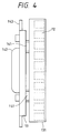
- Fig.4 is a side view depicting the relation between the temperature control jackets on the front side of the electrophoretic part and the press plate.
- gel material to be used in the example of the present invention use may be made of general gels such as polyacrylamide. Additionally, so-called gradient gels or gels with modified levels of denaturing agents may satisfactorily be used as well.
- the automatic fluorescent electrophoresis system relating to the example of the present invention is composed of body part 100, the gel electrophoresis part 200 on the front face thereof and control unit 300 on the back face thereof.
- electrophoresis power source 10 In the body part 100, there are arranged electrophoresis power source 10, excitation laser source 40 and fluorescence detector unit (for example, CCD camera) 44 and the like.
- a gel plate comprising gel 1 and glass plates 2,3 in a form of cramping the gel, and gel temperature control jackets 131, 132 in a form of cramping the gel plate from both sides thereof, and the like.
- a sample placing part and upper buffer solution tank 6 On the upper end part of the gel plate are arranged a sample placing part and upper buffer solution tank 6; on the lower end part thereof is arranged lower buffer solution tank 5.
- control unit part 300 In the control unit part 300 are arranged calculation, signal processing and control unit 45, recording and output unit 46, liquid circulating unit with temperature control unit 50 and dry air source 136 and the like.
- Gel 1 is placed between the glass plate 2 and the notched glass plate 3, to compose the gel plate.
- the method for preparing a gel plate comprises pouring a non-gelatinized material into the space with spacers 35, 35 interposed between the glass plates 2,3, and composing the gel upper face throughout the entire regions from the left end to the right end in parallel to the lower end face, by using a spacer of a width corresponding to the distance from the left spacer to the right spacer, as a spacer for the gel upper end face, so as to form the gel end face in which shirk comb 61 is inserted.
- the spacer for the upper end face is removed, and then, by using shirk comb 61 corresponding to the notch width of the gel upper end face, the upper buffer solution covers the whole upper gel end face so that an electric field can be applied vertically at high precision during electrophoresis.
- the electric field applied to the gel is not distorted even in a high electric field, to enable stable electrophoresis.
- the spacer 35 spacer on the left side of Fig. 2 on the laser beam-incident face, use was made of an acrylic resin material with certified flatness and transparency of the incident end face.
- the glass plates 2,3 of a 20-cm square were used as standards, and the size of the gel prepared from the plates was 19 cm (width) x 15 cm (length) x 0.35 mm (thickness). But these sizes of the glass plates and gel are only illustrated representatively. These sizes should be changed appropriately, depending on the analytical method, the gel material, and the type of a biological sample to be separated. Because the gel thickness is highly responsible for the generation of Joule's heat as a significant issue of the present invention, these sizes should be determined particularly carefully. Depending on a variety of purposes of analysis, the thickness should be selected, and therefore, the thickness cannot be defined generally. The thickness of for example polyacrylamide gel should be within a practical range of 0.1 to 0.4 mm.
- the material of the glass plates 2,3 should have properties to confer surface flatness and higher thermal conductivity together with the properties to attain uniform thickness; and additionally, the material should have good optical transmission with no fluorescent substance contained therein, from the respect of automatic detection via fluorescent labeling.
- quartz glass is preferably used as such material.
- the thickness of the glass plates is preferably thin, but the glass plates have to serve for the purpose of flatly holding the gel, and therefore, the plates should be of a thickness with no distortion under the weight of itself.
- non-fluorescent quartz glass of a thickness of 5 mm was used.
- sample groove 4 For forming sample groove 4, generally, use was made of shirk comb 61 concurrently used. Through the contact of the shirk comb 61 with the gel 1, a plurality of sample grooves 4, 4, 4, --- are formed. Then, individual samples are filled in the individual sample grooves 4,4,---. More specifically, a plurality of biological samples are separately retained in the individual plural grooves formed on the gel upper end face, and these samples are separable under the same conditions during electrophoresis.
- the pitch of the sample grooves formed by the shirk comb 61 may be determined freely, depending on the sample number to be analyzed simultaneously. A greater number of samples can be analyzed simultaneously at a smaller pitch.
- the optical system is configured to count samples simultaneously on a vertical line to the electrophoretic direction, so at some pitch, the sensitivity will never severely be reduced.
- a multi-head divider at a head pitch corresponding to the pitch of the sample well of the microtiter plate should be used.
- n is an integer
- n is an integer
- Six sets of the dividing procedures can introduce the samples continuously into the 48 sample grooves. If two sets of the above procedures are repeated, 12 sets of dividing procedures in total can introduce the samples in all of the 96 sample grooves. Then, the distance from the right end to the left end of the sample grooves is about 15 cm.
- the gel plate is arranged at a state cramped between the gel temperature control jackets 131, 132 from both sides thereof; as described below, a coolant transferred out of the liquid circulating unit with temperature control unit 50 and adjusted to an appropriate temperature circulates through tube 29 in the temperature control jackets 131, 132, to control the temperature of the gel plate.
- the laser beam from excitation laser source 40 is incident in parallel to the lower end face of the gel plate through collimating lens 41 and mirror 421 onto a predetermined position in proximity to the lower end part of the gel plate, and the fluorescence from a sample excited via the laser beam is transmitted through slit 134 on the jacket 132 at the position corresponding to the laser beam incident position, and is detected through mirror 422 and polar screen 43 by fluorescence detection unit 44.
- the upper end face and lower end face of the gel 1 are immersed in buffer solutions 5 reserved in upper buffer solution tank 6 and lower buffer solution tank 7, respectively.
- Notched end face of the notched glass plate 3 is beveled, which helps top parts of syringes and the like readily inserted into the sample grooves when the samples are to be introduced therein.
- the upper buffer solution tank 6 is fixed with clip (not shown in the figures) or the like onto the external face of the notched glass plate 3, and a notch of the same shape as the notch of the glass plate is arranged on the upper buffer solution tank 6 and additionally, sealing material 8, preferably silicon sponge, is arranged following the shape of the notch, to compose a structure such that the leakage of the buffer solution 5 never occurs from the upper buffer solution tank 6.
- Platinum wire 34 is fixed in each of the upper and lower buffer solution tanks, and one end thereof is connected to banana-clip-type plug 91 or 92, and the plugs 91, 92 are individually connected to power source cable 11 connected to electrophoretic power source 10.
- jackets 132, 131 with duct line 12 arranged therein On both sides of the gel plate are pressed and attached, via press plate 19, a pair of jackets 132, 131 with duct line 12 arranged therein.
- As the material of the jackets 131, 132 aluminum casting (surface treated with alumite) is used, and therefore, these jackets have good thermal conductivity.
- the jackets are attached closely through highly heat-conductive silicon rubber 133 of a 0.3 mm thickness (see Fig. 6) to the glass faces, so as to maintain face contact thereof and never deteriorate the heat conduction.
- the press plate 19 can be removed when the gel plate is inserted or removed at the preparation and completion stages of electrophoresis; and that during electrophoresis, the press plate 19 can keep the gel plate and the jackets 131, 132 attached closely together at the position shown in Fig.1, so a hinge structure and a cramp mechanism for the press plate 19 should be placed between box 31 of the body part 100 and the press plate 19. For simplification, however, the cramp mechanism is not shown in the figure.
- the jackets 131, 132 are essentially of the same structure, but the jacket 132 covers a wider area than the whole gel area, while the jacket 131 covers a narrower area by the top end surface of the gel than the whole gel area.
- Duct line 12 is arranged in a snaking fashion over the whole face of each of the jackets 131, 132.
- On both the ends of the individual duct lines are arranged individually joints 15, 15 and the duct line on the lower back face of the jacket 132 is connected through the joint 15 to liquid circulating unit 50, for a coolant to be circulated from the unit into the duct line.
- the duct line on the upper side face of the jacket 132 is connected through the joint 15 to the duct line on the lower side face of the jacket 131, to transfer the coolant passing through the duct line 12 of the jacket 132 into the duct line 12 of the jacket 131.
- the coolant passing through the duct line 12 of the jacket 132 is circulated back into the liquid circulating unit 50, where the coolant is controlled to a predetermined temperature and again recycled to the duct line of the jacket 132.
- the cross section of the duct line 12 is rectangle, which is of a width of 10 mm and a depth of 6 mm in the jacket 132 or which is of a width of 8 mm and a depth of 6 mm in the jacket 131.
- the thickness of the aluminium plate present between the duct line 12 and the glass 3 is 1 mm.
- the aluminium plate should have a heat resistance as low as possible.
- the thickness of the aluminium plate present between the duct line 12 and atmospheric air has a relatively large thermal resistance.
- the aluminium plate is surrounded by a material with a larger heat resistance, for example bakelite of a thickness of 2 mm.
- the cross-sectional area of the plate duct line 12 is a determinant of the liquid flow therein, and so as to increase the heat conductivity at a higher flow, the cross-sectional area of the duct line 12 should be designed smaller.
- the jacket 131 On the front side of the jacket 131, six springs 141, 141,--- are arranged between the press plate 19 and the jacket 131, and when the press plate 19 is fixed at a predetermined position for electrophoresis, the jacket 131 is pushed against the gel plate.
- the gel plate is put at a state such that the gel is cramped from both sides thereof with holders 24, 24,----- fixed on the box 31 of the body part 100, and both the ends of the lower end part are supported by means of supporting block 38.
- the pressure via the springs 141, 141, --- structurally works to closely attach together the jacket 131, the gel plate and the jacket 132, to effectively realize heat conduction via the face contact.
- One end of the press plate 19 is supported by means of the hinge structure 143 fixed on the box 31 of the body part 100, so the press plate can be rotated around the end functioning as the supporting point.
- the cramp not shown in the figure should be removed, and by subsequently pulling handle 142, the press plate 19 and the jacket 131 are integrally opened.
- detecting slit 134 is arranged at a position 12 mm above the gel lower end face on the jacket 132. From the side face at the position of the slit 134, laser beam irradiates the gel 1, whereby the fluorescence corresponding to the laser beam excitation and being emitted from a sample on the gel 1 during electrophoresis can be detected through the slit 134.
- the width of the slit 134 is 5 mm, and the temperature control variation on the gel face due to the presence of the slit is at maximum about 10 % of the temperature difference between the gel and the jacket.
- a narrower slit width can effect more precisely such temperature control, but if the width is too narrow, it prevents detection.
- the width is defined as 5 mm.
- the inner wall of the slit 134 and the external jacket 131 corresponding to the position thereof should be colored black, to structurally prevent the occurrence of irregular fluorescent reflection.
- the jacket 131 has the same duct line cross section and wall thickness as those of the jacket 132, but the jacket 131 has no slit.
- tube 29 is connected to joint 15 in a part of the electrophoresis unit thus structured, and when liquid circulating unit with temperature control unit 50 is connected to the tube 29, then, circulating water or another coolant adjusted to an appropriate temperature can flow in the electrophores is part. Because the channel formed in the jacket is of a snaking form, and the temperature of gel plate is controlled from both sides thereof, an effective temperature control can be realized at the high heat exchange efficiency.
- the flow direction of the coolant into the formed duct line 12 is as follows; the coolant flows starting the bottom part of the jacket 132 on the back face and flows through the duct line 12 out of the joint 15 in the upper part of the jacket 132, and then, the coolant flows in the bottom part of the jacket 131 on the front face and flows through the duct line 12 out of the upper part of the jacket 131, and then returns into the liquid circulating unit with temperature control unit .
- the liquid flow starts in the bottom part of the jackets, so the air inside the duct line 12 at the initial stage can be purged, to attains stable liquid flow.
- the material of the tube 29 is preferably silicon rubber protected with an insulating material.
- "31" is rectangle box and supporting table of the shape of character L.
- On the vertical face of the character L are arranged slit-equipped temperature control jacket 132 and holder 24; while on the horizontal face of the character L is arranged guide 33 so as to mount the lower buffer solution tank 7 at a predetermined position.
- a gel plate is positioned and arranged on the supporting table 31 as has been described above, and then, the plate is fixed by means of the press plate, the cramp 14 and the jacket 131.
- dark chamber comprising the lid part 60 and the box and supporting table 31 can be configured.
- the calculation, signal processing and control unit 45 orders to supply and spray dry air reserved in dry air tank 136, through dry air supply pulp 135, mainly over the detection slit 134, when the jacket temperature is lowered below room temperature.
- Electrophoresis power source 10 and liquid circulating unit with temperature control unit 50 are controlled by means of the calculation, signal processing and control unit 45.
- electrophoresis power source 10 can effect feedback control of a constant voltage, a constant current and a constant power.
- the liquid circulating unit with temperature control unit 50 can control the temperature of the coolant to be circulated into the jackets 131 and 132.
- the liquid circulating unit with temperature control unit 50 performs temperature control at a liquid flow of 10 liters/min within a temperature range of -30 °C to 90 °C and at a precision of ⁇ 0.1 °C.
- the calculation, signal processing and control unit 45 after input with these objective levels can effect individual controls based on the results according to the calculation formulas 1 and 2 with given parameters.
- the detection mechanism comprises laser beam source 40 emitting a laser beam at a specific wave length, collimating lens 41 for collimating the laser beam, mirrors 421, 422, polar screen 43 and CCD camera 44. Additionally as the analysis systems, there are arranged computer and memory unit 45 for incorporating the electric signal generated in the CCD camera 44, and the output unit 46, to convert the resulting electric signal into numerical data or image date for analyzing the electrophoresis. Sample to be subjected to the unit should be preliminarily labeled with fluorescence, and therefore, a label appropriate for the excitation beam should be selected. For example, fluorescein isothianate (FITC) is the most appropriate for argon laser, while texas red is suitable for helium-neon laser.
- FITC fluorescein isothianate
- the above structure is placed in a dark chamber comprising the supporting table 31 and the lid part 60.
- electrophoresis is then carried out by presetting the temperature of the water flow to the gel temperature appropriate for good separation during electrophoresis, the sample filled in the gel groove is moved at a strictly temperature controlled state in the gel region (separation zone), until the sample reaches the excitation beam detection zone with a detection window arranged.
- the fluorescence is received and detected, through slit 134 structured in the jacket 132, and the detected signals are incorporated sequentially over time into the calculation, signal processing and control unit 45, where the signals are converted into image data and numerical data.
- the upper voltage limit durable for electrophoresis should be determined on the basis of the upper limit of the band width being enlarged due to the voltage during electrophoresis but still holding the separation potency, so the upper voltage limit is not restricted to the level described above.
- the sample analyzed by the genetic analysis described in Japanese Patent Laid-Open No. Hei 08-105858 was again analyzed by using the system of the present invention.
- Subjective genes are not limited to those described in this example; the system is effectively used for a variety of DNA regions such as DNA polymorphism site and mutation site.
- the region is analyzed by the asymmetric PCR-SSCP method in accordance with the present invention.
- genomic DNA of about 1 mg was extracted from the whole blood (50 ml), and using 0.1 mg of the DNA as a template, a PCR reaction solution was prepared in the same manner as described in Japanese Patent Laid-open No. Hei 07-209292 for PCR. Subsequently, asymmetric PCR was carried out by the same method as described in Japanese Patent Laid-open No. Hei 07-209292, and 2 ml of the resulting reaction product was mixed with 2 ml of formamide for electrophoresis. However, a fluorescent label rhodamine X isothianate (XRITC), was used by the method described in Japanese Patent Laid-open No. Hei 07-209292, while texas red at an excitation wave length of 594 nm and a fluorescence wave length of 613 nm, was used as a fluorescent label in the present example.
- XRITC fluorescent label rhodamine X isothianate
- Fig.5 is a schematic view depicting the analysis results in accordance with the present invention, wherein data corresponding to one sample groove are shown among all the data.
- eight types of samples namely 0101, 0102, 0103, 0201, 0301, 0401, 0501, and 0601 of the HLA-DQA region, were mixed together and placed.
- Eight peaks in the figure represent the time required for a single-stranded sense DNA of the HLA-DQA region to be electrophoresed to the detecting position; in other words, the peaks correspond to electrophoretic band patterns.
- the figure shows that all the eight types of polymorphism were separated.
- the types of these samples were all preliminarily determined by DNA sequencing, and the individual peaks correspond to the types 0201, 0501, 0103, 0301, 0401, 0601, 0101, and 0102 from left.
- 3.6kV 240 V/cm
- the power level then applied was 300 W on average, and the temperature of the coolant flowing inside the jacket was -1.6 °C.
- the difference between the gel temperature and the temperature control units (jackets 131, 132) at a predetermined voltage applied and a power level, corresponding to the temperature difference in the coolant, is calculated according to the formula 1, so that the temperature of the coolant should be controlled so as to set the gel temperature at an objective value. If a voltage at a constant power level, namely a constant heat generation, is applied during electrophoresis, the temperature of the coolant is to be constant.
- the current level is decreased due to the pH change of the buffer at a high voltage, involving the change of the power level; if the temperature of the coolant changes depending on the power level occasionally monitored, however, the gel temperature can be kept constant. Practically, the response of the coolant is about 1 °C/min, but the change of the current level (namely the change of power level) is about 0.3 W/min. Therefore, the coolant can be controlled satisfactorily.
- Fig.6 is a schematic view depicting the temperature control jackets and gel plate of the present system.
- the gel is uniformly (equally) temperature controlled from both of the left and right sides of the figure.
- a heat transfer model a heat transfer model with an heat source in the center should be assumed satisfactory (calculation formula 1).
- the heat conductivity "h2" is calculated to be 5.4 x 10 W/m ⁇ K.
- the lid part 60 of the placing part 200 in the gel electrophoresing part should be arranged with a low-temperature control function to generate preferentially mildew on the lid part 60, along with duct line 62 to discharge water droplet, whereby the occurrence of mildew on the jackets should preferably be prevented.
- the lid part 60 should be made of a material with good heat transfer properties, and a Peltier element is attached onto the inside thereof, and then, setting the side of the lid part 60 at high temperatures, the side of the placing part 200 can be set at lower temperatures, where the Peltier element can induce mildew, whereby the occurrence of mildew can be prevented on the jackets.
- the fluorescence detector is of a surface detection type (CCD) capable of detecting signal light transmitted through the slit 134, but it is needless to say that the detector may satisfactorily be of a type such that a laser beam source and a detector are integrated together to irradiate an excitation beam and detect signal light at the mechanically scanned position of a slit.
- CCD surface detection type
- the denaturing agent was urea at a concentration of 7 M.
- the analysis of a sample with a DNA fragment with 400 bases was completed in 30 minutes, to generate good nucleotide sequence data.
- the time required for the electrophoresis is about 1/10 fold the separation time required for conventional DNA sequencing, which indicates that very rapid separation can be carried out under the present conditions.
- a short fragment such as PCR product can be analyzed in a short time because the electrophoresis thereof takes as short a time as about 30 minutes, and therefore, after the completion of first electrophoresis, intermediate electrophoresis should be carried out for discharging the remaining sample for about 10 minutes. In such case, a fresh sample can be introduced again for DNA sequencing.
- DNA sequencing can be repeated.
- fragments of about 400 bases could be continuously analyzed three to four times, depending on the fragment length to be analyzed. This may possibly be due to the advantage of the present invention, such that precise temperature control can cause extremely lesser deterioration of the gel.
- both of the simple fragment analysis represented by SSCP and RFLP, and detailed sequence analysis by DNA sequencing can be carried out very speedily, by using two substantially same analyzer mentioned above sequentially, where a appropriate gel for each analyzer is chosen.
- processes from the screening to detailed sequence analysis of a mutant gene can be configured as a sequential system.
- Fig.7 is a flowchart depicting an example realizing the screening to detailed sequence analysis by a series of procedures.
- a sample containing at least one target gene is prepared (301).
- a first reaction process for selectively amplifying the target gene is done (302). More specifically, for example, the process is PCR.
- a part of a sample produced by amplifying a preliminarily selected region, namely a part of the PCR product is subjected to screening by a simple fragment analysis, for example, SSCP, by using the DNA analyzer of the present example, to identify a reaction product with a signal different from normal one or a reaction product specified by the operator (303).
- SSCP simple fragment analysis
- the DNA analyzer of the present example to identify a reaction product with a signal different from normal one or a reaction product specified by the operator (303).
- a second reaction process as the pretreatment for DNA sequencing (304).
- This process corresponds to a process of carrying out the sequencing reaction by the Sanger method. Subsequently, a part of the second reaction product is sequenced by the DNA analyzer of the example (305).
- the screening as step 303 and the sequencing as step 305 are the same in terms of the apparatus structure used and the procedures using the apparatus, except for the gel composition for separation and separation conditions (temperature and electric field intensity).
- an operator should charge preliminarily prepared individual gel carriers in each of two sets of such DNA analyzer, to effect the first reaction process for screening on the first DNA analyzer and to effect the second reaction process for serial DNA sequencing on the second DNA analyzer, using the results generated above.
- preliminary electrophoresis for about 10 minutes after first electrophoresis as described above can directly be proceeded to next electrophoresis with no gel change.
- DNA sequencing is carried out on the second DNA analyzer, therefore, a first reaction process of next group of samples and the screening procedure thereof on the first DNA analyzer can be carried out satisfactorily.
- first and second reaction systems use may be made of the same reaction system as disclosed in Japanese Patent Laid-open No. Hei 6-327476.
- the serial screening and DNA sequencing processes are illustrated in an example of the mutation analysis of a tumor suppresser gene p53.
- the subject was genomic DNA; eight regions of the p53 gene, namely exon 4 (320), 5 (222), 6(149), 7 (153), 8 (170), 9 (104), 10 (142), and 11 (133), were analyzed (In parenthesis, the nucleotide length of each amplified product is shown).
- As the PCR primer sequence and PCR conditions those described in Oncogene, 7, pp. 451 - 457, 1992 by Sameshima et. al. were selected.
- DNAs are extracted from a subjective sample and control (normal sample) by a standard procedure, and a region to be analyzed should be PCR amplified on the first reaction system.
- a region to be analyzed should be PCR amplified on the first reaction system.
- 48 samples were amplified from each exon.
- a part (10 %) of the amplification product is introduced in the DNA analyzer to carry out screening of the mutant gene by the SSCP method.
- electrophoretic separation was carried out at a gel temperature of 20 °C and an electric field intensity of 160 V/cm. In about 60-minute electrophoresis, all the samples were separated.
- a sample observed to have a pattern different from normal one should be identified. Then, only the designated sample is transferred to the second reaction system, where purification and sequencing thereof are carried out. Among the 48 samples simultaneously analyzed, up to 8 of the samples were observed with variation of the patterns after the screening. More specifically, the efficiency was improved by about 5-fold or more by such screening. Generally, one gene is composed of a plurality of exon regions, so such high level of the efficiency can be expected naturally.
- the purification was carried out by standard procedures, including ethanol precipitation; the sequencing was carried out through direct sequencing by the Sanger method using a primer label of a single color (texas red).
- the samples prepared on the second reaction system are placed in the DNA analyzer placing therein the gel of the composition shown in second Example for DNA sequencing.
- the electric field intensity was 120 V/cm, but any of the samples could be electrophoresed within 30 minutes because the subjective fragment length was short.
- the DNA sequences of only 12 samples could be simultaneously determined in 48 lanes. Since the analyzing subjects were restricted to 4 to 8 samples via the screening, however, the processing ability thereof was satisfactory. In other words, the present system can carry out all the processes of mutation analysis in a sequentially, because the sequencing reaction process and DNA sequencing process do not work any more as rate-determining steps therein since sample number for second analysis is reduced by screening done by first analysis. Additionally, in accordance with the present invention, high-speed screening and high-speed DNA sequencing are attained so that the process from screening to DNA sequencing of 48 samples could be completed in about 5 hours.
- the processing time was assigned as follows; 1.5 hours on the first reaction unit; one hour for SSCP analysis on the DNA analyzer; 2 hours on the second reaction unit; and 30 minutes for DNA sequencing on the DNA analyzer.
- the time required for screening and the time required for DNA sequencing are equally 2.5 hours.
- two sets of the DNA analyzer of the present invention are independently used for screening and DNA sequencing, the procedures therefore can progress in sequentially.
- 384 samples in total 48 samples x 8 exon regions
- 384 samples in total require approximately 96 hours.
- the gel including a part irradiated with an excitation beam during electrophoresis can be temperature controlled overall at a higher efficiency, and even at a higher voltage applied, a highly reproducible and markedly separated electrophoretic pattern by SSCP analysis or DNA sequencing can be generated. All the processes from the screening to DNA sequencing of a mutant gene can be practiced speedily and highly efficiently.
Landscapes
- Health & Medical Sciences (AREA)
- Life Sciences & Earth Sciences (AREA)
- Molecular Biology (AREA)
- Chemical & Material Sciences (AREA)
- Chemical Kinetics & Catalysis (AREA)
- Electrochemistry (AREA)
- Physics & Mathematics (AREA)
- Analytical Chemistry (AREA)
- Biochemistry (AREA)
- General Health & Medical Sciences (AREA)
- General Physics & Mathematics (AREA)
- Immunology (AREA)
- Pathology (AREA)
- Investigating, Analyzing Materials By Fluorescence Or Luminescence (AREA)
- Apparatus Associated With Microorganisms And Enzymes (AREA)
- Measuring Or Testing Involving Enzymes Or Micro-Organisms (AREA)
- Investigating Or Analysing Biological Materials (AREA)
Applications Claiming Priority (3)
| Application Number | Priority Date | Filing Date | Title |
|---|---|---|---|
| JP10256696A JP3418292B2 (ja) | 1996-04-24 | 1996-04-24 | 遺伝子解析装置 |
| JP10256696 | 1996-04-24 | ||
| JP102566/96 | 1996-04-24 |
Publications (2)
| Publication Number | Publication Date |
|---|---|
| EP0803730A2 true EP0803730A2 (de) | 1997-10-29 |
| EP0803730A3 EP0803730A3 (de) | 1999-07-07 |
Family
ID=14330781
Family Applications (1)
| Application Number | Title | Priority Date | Filing Date |
|---|---|---|---|
| EP97106804A Withdrawn EP0803730A3 (de) | 1996-04-24 | 1997-04-24 | DNA-Analysegerät |
Country Status (3)
| Country | Link |
|---|---|
| US (1) | US5976338A (de) |
| EP (1) | EP0803730A3 (de) |
| JP (1) | JP3418292B2 (de) |
Cited By (2)
| Publication number | Priority date | Publication date | Assignee | Title |
|---|---|---|---|---|
| EP1733218A4 (de) * | 2004-03-15 | 2009-03-18 | D N R Imaging Systems Ltd | Verfahren und system zur überwachung eines materialtrennvorgangs, wie etwa eines elektrophoresevorgangs, in einer probe |
| CN104569115A (zh) * | 2015-01-09 | 2015-04-29 | 上海海洋大学 | 控温循环装置及包含该装置的凝胶电泳系统 |
Families Citing this family (22)
| Publication number | Priority date | Publication date | Assignee | Title |
|---|---|---|---|---|
| US7875440B2 (en) | 1998-05-01 | 2011-01-25 | Arizona Board Of Regents | Method of determining the nucleotide sequence of oligonucleotides and DNA molecules |
| US6780591B2 (en) | 1998-05-01 | 2004-08-24 | Arizona Board Of Regents | Method of determining the nucleotide sequence of oligonucleotides and DNA molecules |
| US6821402B1 (en) * | 1998-09-16 | 2004-11-23 | Applera Corporation | Spectral calibration of fluorescent polynucleotide separation apparatus |
| US6818395B1 (en) | 1999-06-28 | 2004-11-16 | California Institute Of Technology | Methods and apparatus for analyzing polynucleotide sequences |
| US6372106B1 (en) * | 1999-07-26 | 2002-04-16 | Applera Corporation | Capillary electrophoresis method and apparatus for reducing peak broadening associated with the establishment of an electric field |
| US6665060B1 (en) * | 1999-10-29 | 2003-12-16 | Cytyc Corporation | Cytological imaging system and method |
| JP2004523243A (ja) | 2001-03-12 | 2004-08-05 | カリフォルニア インスティチュート オブ テクノロジー | 非同期性塩基伸長によってポリヌクレオチド配列を分析するための方法および装置 |
| EP1629080B1 (de) * | 2003-04-30 | 2017-07-05 | William R. Moyle | Verfahren zum biomolekularen nachweis und zur zellklassifizierung |
| US7169560B2 (en) | 2003-11-12 | 2007-01-30 | Helicos Biosciences Corporation | Short cycle methods for sequencing polynucleotides |
| WO2005080605A2 (en) | 2004-02-19 | 2005-09-01 | Helicos Biosciences Corporation | Methods and kits for analyzing polynucleotide sequences |
| US7635562B2 (en) | 2004-05-25 | 2009-12-22 | Helicos Biosciences Corporation | Methods and devices for nucleic acid sequence determination |
| US7476734B2 (en) | 2005-12-06 | 2009-01-13 | Helicos Biosciences Corporation | Nucleotide analogs |
| US7220549B2 (en) | 2004-12-30 | 2007-05-22 | Helicos Biosciences Corporation | Stabilizing a nucleic acid for nucleic acid sequencing |
| US7482120B2 (en) | 2005-01-28 | 2009-01-27 | Helicos Biosciences Corporation | Methods and compositions for improving fidelity in a nucleic acid synthesis reaction |
| US7666593B2 (en) | 2005-08-26 | 2010-02-23 | Helicos Biosciences Corporation | Single molecule sequencing of captured nucleic acids |
| US7397546B2 (en) | 2006-03-08 | 2008-07-08 | Helicos Biosciences Corporation | Systems and methods for reducing detected intensity non-uniformity in a laser beam |
| US7811810B2 (en) | 2007-10-25 | 2010-10-12 | Industrial Technology Research Institute | Bioassay system including optical detection apparatuses, and method for detecting biomolecules |
| US7767441B2 (en) * | 2007-10-25 | 2010-08-03 | Industrial Technology Research Institute | Bioassay system including optical detection apparatuses, and method for detecting biomolecules |
| US8593164B2 (en) | 2009-10-16 | 2013-11-26 | Brigham Young University (Byu) | Cell for broadband dielectric spectroscopy |
| JP5984080B2 (ja) * | 2011-12-22 | 2016-09-06 | シャープ株式会社 | 制御方法、制御装置、制御システム、及び制御プログラム |
| JP2014219218A (ja) * | 2013-05-01 | 2014-11-20 | システム・インスツルメンツ株式会社 | 電気泳動用ゲルホルダおよび電気泳動方法 |
| WO2024202827A1 (ja) | 2023-03-31 | 2024-10-03 | 富士フイルム株式会社 | 分析装置 |
Family Cites Families (7)
| Publication number | Priority date | Publication date | Assignee | Title |
|---|---|---|---|---|
| US3719580A (en) * | 1971-06-04 | 1973-03-06 | R Roberts | Electrophoretic apparatus |
| US5360523A (en) * | 1984-03-29 | 1994-11-01 | Li-Cor, Inc. | DNA sequencing |
| US5230781A (en) * | 1984-03-29 | 1993-07-27 | Li-Cor, Inc. | Sequencing near infrared and infrared fluorescence labeled DNA for detecting using laser diodes |
| US4787088A (en) * | 1985-03-20 | 1988-11-22 | Fuji Photo Film Co., Ltd. | Semiconductor laser beam source apparatus |
| US5085757A (en) * | 1987-11-25 | 1992-02-04 | Northeastern University | Integrated temperature control/alignment system for high performance capillary electrophoretic apparatus |
| JPH0798276A (ja) * | 1993-09-28 | 1995-04-11 | Hitachi Electron Eng Co Ltd | Dna塩基配列決定装置 |
| JP3345190B2 (ja) * | 1994-10-07 | 2002-11-18 | 株式会社日立製作所 | ゲル電気泳動装置 |
-
1996
- 1996-04-24 JP JP10256696A patent/JP3418292B2/ja not_active Expired - Fee Related
-
1997
- 1997-04-22 US US08/837,816 patent/US5976338A/en not_active Expired - Fee Related
- 1997-04-24 EP EP97106804A patent/EP0803730A3/de not_active Withdrawn
Cited By (3)
| Publication number | Priority date | Publication date | Assignee | Title |
|---|---|---|---|---|
| EP1733218A4 (de) * | 2004-03-15 | 2009-03-18 | D N R Imaging Systems Ltd | Verfahren und system zur überwachung eines materialtrennvorgangs, wie etwa eines elektrophoresevorgangs, in einer probe |
| CN104569115A (zh) * | 2015-01-09 | 2015-04-29 | 上海海洋大学 | 控温循环装置及包含该装置的凝胶电泳系统 |
| CN104569115B (zh) * | 2015-01-09 | 2017-06-16 | 上海海洋大学 | 控温循环装置及包含该装置的凝胶电泳系统 |
Also Published As
| Publication number | Publication date |
|---|---|
| US5976338A (en) | 1999-11-02 |
| JPH09288091A (ja) | 1997-11-04 |
| JP3418292B2 (ja) | 2003-06-16 |
| EP0803730A3 (de) | 1999-07-07 |
Similar Documents
| Publication | Publication Date | Title |
|---|---|---|
| EP0803730A2 (de) | DNA-Analysegerät | |
| Hongyo et al. | ‘Cold SSCP’: a simple, rapid and non-radioactive method for optimized single-strand conformation polymorphism analyses | |
| EP0157280B1 (de) | Bestimmung von einer DNS-Sequenz | |
| JP3467995B2 (ja) | キャピラリー電気泳動装置 | |
| CA2049429C (en) | Dna sequencing | |
| US6156178A (en) | Increased throughput analysis of small compounds using multiple temporally spaced injections | |
| US6596487B2 (en) | Mutation detection using denaturing gradients | |
| EP2937685B1 (de) | Verfahren für genotypische analysen | |
| US5541420A (en) | Multi-sample fraction collector by electrophoresis | |
| JP3713970B2 (ja) | 特異的遺伝子断片の分離採取装置 | |
| JPH09505669A (ja) | ポリヌクレオチド断片の分析用改良の実時間走査型螢光電気泳動装置 | |
| US7195698B2 (en) | Capillary electrophoretic apparatus, sample plate and sample injection method | |
| US6290831B1 (en) | Electrophoretic system for real time detection of multiple electrophoresed biopolymers | |
| CN100357450C (zh) | 检测样品中核酸片段突变的方法和装置 | |
| EP0572023A2 (de) | Elektrophoresevorrichtung | |
| JP2004512850A5 (de) | ||
| US6533912B2 (en) | Increased throughput analysis of small compounds using multiple temporally spaced injections | |
| JP4021215B2 (ja) | 電気泳動方法 | |
| JPH0814537B2 (ja) | Dna配列決定のための実時間走査電気泳動装置 | |
| WO2001077386A2 (en) | High-throughput detection of unknown dna mutations by using multiplexed capillary electrophoresis | |
| EP1320745A1 (de) | System und verfahren zur temperaturgradienten-kapillarelektrophorese | |
| JP2003227813A (ja) | キャピラリー電気泳動装置 | |
| JPH08105858A (ja) | ゲル電気泳動装置 | |
| JP2000137020A (ja) | マルチキャピラリー電気泳動装置 | |
| US20030150728A1 (en) | Method and device for separating marked biopolymers |
Legal Events
| Date | Code | Title | Description |
|---|---|---|---|
| PUAI | Public reference made under article 153(3) epc to a published international application that has entered the european phase |
Free format text: ORIGINAL CODE: 0009012 |
|
| AK | Designated contracting states |
Kind code of ref document: A2 Designated state(s): CH DE FR GB LI SE |
|
| PUAL | Search report despatched |
Free format text: ORIGINAL CODE: 0009013 |
|
| AK | Designated contracting states |
Kind code of ref document: A3 Designated state(s): CH DE FR GB LI SE |
|
| 17P | Request for examination filed |
Effective date: 19991227 |
|
| RIN1 | Information on inventor provided before grant (corrected) |
Inventor name: MIYAZAKI, YUUSUKE, NISSHIN-HAITSU-NAGAHAMA 202 Inventor name: MURAMATSU, TAKAMICHI Inventor name: UMEMURA, SHIN-ICHIRO Inventor name: KIYAMA, MASAHARU Inventor name: FUJITA, TAKESHI, HITACHI-HATOYAMA-RYO 103 |
|
| STAA | Information on the status of an ep patent application or granted ep patent |
Free format text: STATUS: THE APPLICATION IS DEEMED TO BE WITHDRAWN |
|
| 18D | Application deemed to be withdrawn |
Effective date: 20060503 |