EP0803748B1 - Fiche d'un connecteur à fibres optiques multiples - Google Patents
Fiche d'un connecteur à fibres optiques multiples Download PDFInfo
- Publication number
- EP0803748B1 EP0803748B1 EP97201004A EP97201004A EP0803748B1 EP 0803748 B1 EP0803748 B1 EP 0803748B1 EP 97201004 A EP97201004 A EP 97201004A EP 97201004 A EP97201004 A EP 97201004A EP 0803748 B1 EP0803748 B1 EP 0803748B1
- Authority
- EP
- European Patent Office
- Prior art keywords
- connector plug
- coupling
- coupling body
- sleeve
- spring
- Prior art date
- Legal status (The legal status is an assumption and is not a legal conclusion. Google has not performed a legal analysis and makes no representation as to the accuracy of the status listed.)
- Expired - Lifetime
Links
- 230000008878 coupling Effects 0.000 claims description 68
- 238000010168 coupling process Methods 0.000 claims description 68
- 238000005859 coupling reaction Methods 0.000 claims description 68
- 230000003287 optical effect Effects 0.000 claims description 12
- 239000000463 material Substances 0.000 claims description 6
- 230000002787 reinforcement Effects 0.000 claims description 5
- 239000004033 plastic Substances 0.000 claims description 3
- 239000013307 optical fiber Substances 0.000 description 4
- 229920000271 Kevlar® Polymers 0.000 description 1
- 238000004026 adhesive bonding Methods 0.000 description 1
- 230000003247 decreasing effect Effects 0.000 description 1
- 230000002349 favourable effect Effects 0.000 description 1
- 239000004761 kevlar Substances 0.000 description 1
- 238000004519 manufacturing process Methods 0.000 description 1
Images

Classifications
-
- G—PHYSICS
- G02—OPTICS
- G02B—OPTICAL ELEMENTS, SYSTEMS OR APPARATUS
- G02B6/00—Light guides; Structural details of arrangements comprising light guides and other optical elements, e.g. couplings
- G02B6/24—Coupling light guides
- G02B6/36—Mechanical coupling means
- G02B6/38—Mechanical coupling means having fibre to fibre mating means
- G02B6/3807—Dismountable connectors, i.e. comprising plugs
- G02B6/381—Dismountable connectors, i.e. comprising plugs of the ferrule type, e.g. fibre ends embedded in ferrules, connecting a pair of fibres
- G02B6/3818—Dismountable connectors, i.e. comprising plugs of the ferrule type, e.g. fibre ends embedded in ferrules, connecting a pair of fibres of a low-reflection-loss type
- G02B6/3821—Dismountable connectors, i.e. comprising plugs of the ferrule type, e.g. fibre ends embedded in ferrules, connecting a pair of fibres of a low-reflection-loss type with axial spring biasing or loading means
-
- G—PHYSICS
- G02—OPTICS
- G02B—OPTICAL ELEMENTS, SYSTEMS OR APPARATUS
- G02B6/00—Light guides; Structural details of arrangements comprising light guides and other optical elements, e.g. couplings
- G02B6/24—Coupling light guides
- G02B6/36—Mechanical coupling means
- G02B6/38—Mechanical coupling means having fibre to fibre mating means
- G02B6/3807—Dismountable connectors, i.e. comprising plugs
- G02B6/3869—Mounting ferrules to connector body, i.e. plugs
-
- G—PHYSICS
- G02—OPTICS
- G02B—OPTICAL ELEMENTS, SYSTEMS OR APPARATUS
- G02B6/00—Light guides; Structural details of arrangements comprising light guides and other optical elements, e.g. couplings
- G02B6/24—Coupling light guides
- G02B6/36—Mechanical coupling means
- G02B6/38—Mechanical coupling means having fibre to fibre mating means
- G02B6/3807—Dismountable connectors, i.e. comprising plugs
- G02B6/3873—Connectors using guide surfaces for aligning ferrule ends, e.g. tubes, sleeves, V-grooves, rods, pins, balls
- G02B6/3885—Multicore or multichannel optical connectors, i.e. one single ferrule containing more than one fibre, e.g. ribbon type
-
- G—PHYSICS
- G02—OPTICS
- G02B—OPTICAL ELEMENTS, SYSTEMS OR APPARATUS
- G02B6/00—Light guides; Structural details of arrangements comprising light guides and other optical elements, e.g. couplings
- G02B6/24—Coupling light guides
- G02B6/36—Mechanical coupling means
- G02B6/38—Mechanical coupling means having fibre to fibre mating means
- G02B6/3807—Dismountable connectors, i.e. comprising plugs
- G02B6/389—Dismountable connectors, i.e. comprising plugs characterised by the method of fastening connecting plugs and sockets, e.g. screw- or nut-lock, snap-in, bayonet type
- G02B6/3893—Push-pull type, e.g. snap-in, push-on
Definitions
- the invention relates to a multifibre connector plug, comprising a connector plug part for receiving a plurality of optical fibres, said connector plug part having a contact face at one end, a coupling body, the connector plug part being slidable in said coupling body, wherein the connector plug part projects out of said coupling body with its end having said contact face, and a coupling sleeve enclosing said coupling body and being slidable on said coupling body from a coupling position into a decoupling position against the action of a spring means.
- US 5373574 discloses a connector for an optical fibre which possesses a connector body as a central component which is formed integrally with a receiving socket and with a spring element.
- the connector body has, on two opposing sides, a locking shoulder, which serves to lock the connector into a sleeve portion.
- the invention aims to provide an improved multifibre connector plug of the above-mentioned type.
- the connector plug of the invention has the features of claim 1.
- the coupling sleeve with the spring means is made of plastic material, wherein the spring means is unloaded in the coupling position.
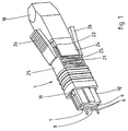
- Fig. 1 shows a perspective view of an embodiment of the multifibre connector plug of the invention, wherein for clarity sake the optical fibre cable is not shown.
- Fig. 2 shows an exploded view of the connector plug of Fig. 1.
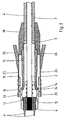
- Fig. 3 shows an axial cross-section of the connector plug of Fig. 1 with an optical fibre cable connected thereto.
- a multifibre connector plug 1 which in a manner known per se can be coupled with a corresponding connector plug for interconnecting a plurality of optical fibres.
- the optical fibres of the connector plug 1 are schematically indicated at 2 in Fig. 3 and are part of an optical fibre cable 3 with an outer jacket 4 and a schematically indicated reinforcement jacket 5 usually made of Kevlar fibres.
- the connector plug 1 is provided with a connector plug part 6, in which the uncovered optical fibres 2 are attached.
- This connector plug part 6 is also indicated as ferrule.
- the connector plug part 6 has a contact face 7, the optical fibres 2 ending in said contact face as indicated by reference numeral 8. Further the connector plug part 6 comprises two holes debouching in the contact face 7 at both sides of the ends of the optical fibres 2, wherein in this case guiding pins 9 are mounted in said holes. The pins 9 will be received in the holes of a corresponding connector plug part if the connector plug 1 is coupled with a corresponding connector plug 1.
- the connector plug part 6 is slidably received within a coupling body 10 assembled of two identical halves 11, wherein the connector plug part 6 projects out of the coupling body 10 with its end having the contact face 7. As shown in Fig. 3, the connector plug part 6 is pressed with an edge 12 against an inner edge 13 of the coupling body 10 by a spring 14. This spring 14 is lying between the connector plug part 6 and a carrier sleeve 15 fixed within the coupling body 10 by means of two locking fingers 16.
- the carrier sleeve 15 has a mounting surface 17 at its end opposite of the coupling body 10, the reinforcement jacket 5 of the optical cable 3 being attached to said mounting surface 17, for example by glueing.
- the connector plug 1 is closed by an end sleeve or boot 18 attached to the end of the carrier sleeve 15 projecting out of the coupling body 10.
- the end sleeve 18 encloses the reinforcement jacket 5 of the optical cable 3.
- the connector plug 1 further comprises a coupling sleeve 19 enclosing the coupling body 10 and being slidable on this coupling body 10 from a coupling position shown in Figs. 1 and 3 into a withdrawn decoupling position not shown.
- the coupling sleeve 19 encloses two recesses 20 provided in opposite sides of the coupling body 10.
- a backpanel adapter for example can engage into said recesses for holding the connector plug 1 in the adapter.
- Decoupling the connector plug 1 is possible by sliding the coupling sleeve 19 into the withdrawn decoupling position against the action of a spring means which after releasing the coupling sleeve 19 moves this coupling sleeve back into the coupling position.
- the spring means comprises two springs 21 which are integrated parts of the coupling sleeve 19 and form a single unit therewith.
- the coupling body 10 and the coupling sleeve 19 have a mainly rectangular cross-section, wherein the springs 21 are located at the two opposite long rectangular sides and join the end of the coupling sleeve 19 directed away from the connector plug part 6.
- the coupling sleeve 19 and the springs 21 are made unitary of plastic material, wherein the springs 21 are unloaded in the coupling position shown in the drawings.
- the springs 21 are made as a substantially sine-shaped material strip joining the material of the coupling sleeve 19.
- the free end of the springs 21 is formed as a straight support section 22 engaging a corresponding support shoulder 23 of the coupling body 10.
- Each support shoulder 23 further carries a cover lip 24 at least substantially covering the corresponding spring 21 whereby damage of the springs 21 is avoided.
- the coupling sleeve 19 carries on both other opposite sides lips 25 extending from the coupling sleeve 19 along an equal length as the springs 21.
- the assembly of the coupling sleeve 19 and the coupling body 10 is a rather simple action, wherein the springs 21 are automatically lying at the correct location.
- the connector plug 1 comprises a relatively low number of parts, wherein mounting of the optical cable 3 is simplified in that the coupling body 10 consists of two halves 11 which can be simply mounted around the cable 3.
- the lips 25 are for example provided with operating lips 26 extending obliquely outwardly in the direction of the end sleeve 18. These operating lips 26 facilitate the movement of the coupling sleeve 19 from the coupling position into the decoupling position.
Landscapes
- Physics & Mathematics (AREA)
- General Physics & Mathematics (AREA)
- Optics & Photonics (AREA)
- Mechanical Coupling Of Light Guides (AREA)
Claims (8)
- Connecteur multifibre (1), comprenant un élément de connecteur (6) permettant de recevoir une pluralité de fibres optiques (2), ledit élément de connecteur ayant une face de contact (7) à une extrémité, un corps d'accouplement (10), l'élément de connecteur étant maintenu de manière à pouvoir coulisser dans ledit corps d'accouplement, dans lequel l'élément de connecteur fait saillie par rapport audit corps d'accouplement, son extrémité ayant ladite face de contact, et un manchon d'accouplement (19) renfermant ledit corps d'accouplement et pouvant coulisser sur ledit corps d'accouplement en passant d'une position d'accouplement à une position de désaccouplement à l'encontre de l'action exercée par des moyens ressort (21), dans lequel lesdits moyens ressort comprennent au moins un ressort (21) qui est un élément unitaire intégré du manchon d'accouplement (19) et vient en prise avec une extrémité libre (22) d'un épaulement de support (23) correspondant du corps d'accouplement (10).
- Connecteur selon la revendication 1, dans lequel le manchon d'accouplement (19) présentant les moyens de ressort (21) est réalisé dans une matière plastique, et dans lequel les moyens ressort sont sans contrainte dans la position d'accouplement.
- Connecteur selon l'une quelconque des revendications 1 ou 2, dans lequel chaque ressort (21) du manchon d'accouplement (19) est une bande de matière présentant une forme sensiblement ondulée, reliée d'un côté au manchon d'accouplement, et débouchant de l'autre côté dans une section de support droite (22) venant en butée contre l'épaulement de support (23) du corps d'accouplement (10).
- Connecteur selon l'une quelconque des revendications précédentes, dans lequel chaque épaulement de support (23) du corps d'accouplement (10) soutient une lèvre (24) recouvrant au moins sensiblement le ressort (21 ) correspondant.
- Connecteur selon l'une quelconque des revendications précédentes, dans lequel le corps d'accouplement (10) et le manchon d'accouplement (19) ont chacun une coupe transversale sensiblement rectangulaire, dans lequel le manchon d'accouplement soutient à une extrémité un ressort intégré (21) sur deux côtés opposés et des lèvres intégrées (25) sur les deux autres côtés opposés, lesdites lèvres (25) s'étendant sur la même longueur par rapport au manchon d'accouplement que les ressorts.
- Connecteur selon la revendication 5, dans lequel les lèvres (25) soutiennent des lèvres fonctionnelles (26) s'étendant obliquement vers l'extérieur.
- Connecteur selon l'une quelconque des revendications précédentes, dans lequel le corps d'accouplement (10) comprend deux moitiés (11) identiques.
- Connecteur selon l'une quelconque des revendications précédentes, dans lequel un manchon de support (15) est fixé dans le corps d'accouplement (10) à l'extrémité opposée à l'élément de connecteur (6), ledit manchon de support, à l'extrémité s'écartant du corps d'accouplement, ayant une surface de montage (17) destinée à une gaine de renforcement (5) d'un câble optique (3) comprenant lesdites fibres optiques (2), dans lequel un embout protecteur (18) est fixé sur ladite extrémité alors qu'on serre la gaine de renforcement.
Applications Claiming Priority (2)
| Application Number | Priority Date | Filing Date | Title |
|---|---|---|---|
| NL1002955 | 1996-04-26 | ||
| NL1002955A NL1002955C2 (nl) | 1996-04-26 | 1996-04-26 | Multifiber connectorplug. |
Publications (2)
| Publication Number | Publication Date |
|---|---|
| EP0803748A1 EP0803748A1 (fr) | 1997-10-29 |
| EP0803748B1 true EP0803748B1 (fr) | 2005-03-23 |
Family
ID=19762737
Family Applications (1)
| Application Number | Title | Priority Date | Filing Date |
|---|---|---|---|
| EP97201004A Expired - Lifetime EP0803748B1 (fr) | 1996-04-26 | 1997-04-09 | Fiche d'un connecteur à fibres optiques multiples |
Country Status (5)
| Country | Link |
|---|---|
| US (1) | US5898808A (fr) |
| EP (1) | EP0803748B1 (fr) |
| JP (1) | JP3669808B2 (fr) |
| DE (1) | DE69732815T2 (fr) |
| NL (1) | NL1002955C2 (fr) |
Cited By (2)
| Publication number | Priority date | Publication date | Assignee | Title |
|---|---|---|---|---|
| CN105223659A (zh) * | 2015-08-31 | 2016-01-06 | 中航光电科技股份有限公司 | 弹性推杆及使用该弹性推杆的插头壳体和子板插头 |
| US20210247571A1 (en) * | 2018-06-28 | 2021-08-12 | Diamond Sa | Connector part for an optical plug-in connection |
Families Citing this family (14)
| Publication number | Priority date | Publication date | Assignee | Title |
|---|---|---|---|---|
| DE10001680C1 (de) | 2000-01-12 | 2001-08-23 | Infineon Technologies Ag | Mehrkanalige optische Koppelanordnung |
| US7680388B2 (en) * | 2004-11-03 | 2010-03-16 | Adc Telecommunications, Inc. | Methods for configuring and testing fiber drop terminals |
| AU2006236409B2 (en) | 2005-04-19 | 2011-05-19 | Adc Telecommunications, Inc. | Loop back plug and method |
| WO2007016963A1 (fr) * | 2005-08-05 | 2007-02-15 | Fci | Ferrule a ressort |
| FR2943429A1 (fr) * | 2009-03-20 | 2010-09-24 | Radiall Sa | Contact optique souple |
| US8915659B2 (en) | 2010-05-14 | 2014-12-23 | Adc Telecommunications, Inc. | Splice enclosure arrangement for fiber optic cables |
| US8885998B2 (en) | 2010-12-09 | 2014-11-11 | Adc Telecommunications, Inc. | Splice enclosure arrangement for fiber optic cables |
| WO2014085462A1 (fr) | 2012-11-30 | 2014-06-05 | Tyco Electronics Corporation | Connecteur à fibre optique avec boîtier extérieur de connecteur pouvant être installé sur place |
| US9312637B2 (en) * | 2013-05-30 | 2016-04-12 | Tyco Electronics Corporation | Communication system having a floatable connector assembly |
| CN104849815B (zh) * | 2014-02-14 | 2017-01-18 | 泰科电子(上海)有限公司 | 光纤连接器及其组装方法 |
| CN104849816B (zh) | 2014-02-14 | 2017-01-11 | 泰科电子(上海)有限公司 | 光纤连接器及其组装方法 |
| CN105445862B (zh) | 2014-07-09 | 2018-01-19 | 泰科电子(上海)有限公司 | 光纤连接器及其现场组装方法 |
| EP4403972A3 (fr) | 2015-11-30 | 2024-10-16 | CommScope Technologies LLC | Connecteur de fibre optique et son assemblage |
| EP3391115A4 (fr) | 2015-12-16 | 2019-07-17 | Commscope Technologies LLC | Connecteur à fibre optique installé sur le terrain |
Family Cites Families (5)
| Publication number | Priority date | Publication date | Assignee | Title |
|---|---|---|---|---|
| GB2062891B (en) * | 1979-10-31 | 1985-07-24 | Bunker Ramo | Fibre optic connector for high density appilications and method of manufacturing fibre optic connectors |
| US4697871A (en) * | 1985-05-28 | 1987-10-06 | Dorran Photonics Incorporated | Termination of optical fibers |
| JPH077139B2 (ja) * | 1985-12-24 | 1995-01-30 | 日本電信電話株式会社 | 浮動ホルダ型光コネクタ |
| DE59302988D1 (de) * | 1992-05-20 | 1996-07-25 | Diamond Sa | Stecker für einen Lichtwellenleiter |
| US5748818A (en) * | 1995-12-22 | 1998-05-05 | Weiss; Roger E. | Massive parallel optical interconnect system |
-
1996
- 1996-04-26 NL NL1002955A patent/NL1002955C2/nl not_active IP Right Cessation
-
1997
- 1997-04-09 EP EP97201004A patent/EP0803748B1/fr not_active Expired - Lifetime
- 1997-04-09 DE DE69732815T patent/DE69732815T2/de not_active Expired - Lifetime
- 1997-04-22 US US08/837,780 patent/US5898808A/en not_active Expired - Lifetime
- 1997-04-24 JP JP10776297A patent/JP3669808B2/ja not_active Expired - Fee Related
Cited By (3)
| Publication number | Priority date | Publication date | Assignee | Title |
|---|---|---|---|---|
| CN105223659A (zh) * | 2015-08-31 | 2016-01-06 | 中航光电科技股份有限公司 | 弹性推杆及使用该弹性推杆的插头壳体和子板插头 |
| CN105223659B (zh) * | 2015-08-31 | 2016-09-21 | 中航光电科技股份有限公司 | 弹性推杆及使用该弹性推杆的插头壳体和子板插头 |
| US20210247571A1 (en) * | 2018-06-28 | 2021-08-12 | Diamond Sa | Connector part for an optical plug-in connection |
Also Published As
| Publication number | Publication date |
|---|---|
| US5898808A (en) | 1999-04-27 |
| DE69732815T2 (de) | 2006-04-06 |
| NL1002955C2 (nl) | 1997-10-28 |
| DE69732815D1 (de) | 2005-04-28 |
| EP0803748A1 (fr) | 1997-10-29 |
| JP3669808B2 (ja) | 2005-07-13 |
| JPH1048473A (ja) | 1998-02-20 |
Similar Documents
| Publication | Publication Date | Title |
|---|---|---|
| EP0803748B1 (fr) | Fiche d'un connecteur à fibres optiques multiples | |
| US6550979B1 (en) | Floating connector subassembly and connector including same | |
| US6019521A (en) | Optical fiber connector | |
| US6224270B1 (en) | Universal optical fiber connectors and basic plugs thereof | |
| CN119644518B (zh) | 一种连接器、适配器和快速插拔的光纤连接组件 | |
| US7972067B2 (en) | Fiber optic connector assembly | |
| US4140365A (en) | Fiber optic cable connector housing | |
| US20020076164A1 (en) | Trigger mechanism, optical cable connector including same, and method of assembling an optical cable connector | |
| US5737464A (en) | Monolithic optical fiber coupler including sleeve with flexible flap | |
| US5828805A (en) | Multifiber connector plug | |
| EP0685750A1 (fr) | Connecteur pour connecter un câble à fibre optique | |
| US20150338581A1 (en) | Optical Connector | |
| US4359256A (en) | Electrical connector coupling member | |
| US6945705B2 (en) | Optical connector | |
| US6010250A (en) | Plug for fibre optic cable | |
| US6206580B1 (en) | Optical connector | |
| US5828806A (en) | Fiber optic connector | |
| US5800199A (en) | Connector alignment guide | |
| KR20220145160A (ko) | 플러그 커넥터 | |
| US6471418B1 (en) | Optical connector | |
| JPH11305071A (ja) | 光コネクタ | |
| GB2124793A (en) | Fibre optic connector | |
| US7416348B2 (en) | Optical connector excellent in assemblability and dimensional accuracy | |
| US11300736B2 (en) | Connector assembly | |
| JPH08643Y2 (ja) | 光コネクタエレメント |
Legal Events
| Date | Code | Title | Description |
|---|---|---|---|
| PUAI | Public reference made under article 153(3) epc to a published international application that has entered the european phase |
Free format text: ORIGINAL CODE: 0009012 |
|
| AK | Designated contracting states |
Kind code of ref document: A1 Designated state(s): BE DE FR GB IT NL SE |
|
| 17P | Request for examination filed |
Effective date: 19980119 |
|
| GRAP | Despatch of communication of intention to grant a patent |
Free format text: ORIGINAL CODE: EPIDOSNIGR1 |
|
| GRAS | Grant fee paid |
Free format text: ORIGINAL CODE: EPIDOSNIGR3 |
|
| GRAA | (expected) grant |
Free format text: ORIGINAL CODE: 0009210 |
|
| AK | Designated contracting states |
Kind code of ref document: B1 Designated state(s): BE DE FR GB IT NL SE |
|
| PG25 | Lapsed in a contracting state [announced via postgrant information from national office to epo] |
Ref country code: NL Free format text: LAPSE BECAUSE OF FAILURE TO SUBMIT A TRANSLATION OF THE DESCRIPTION OR TO PAY THE FEE WITHIN THE PRESCRIBED TIME-LIMIT Effective date: 20050323 Ref country code: IT Free format text: LAPSE BECAUSE OF FAILURE TO SUBMIT A TRANSLATION OF THE DESCRIPTION OR TO PAY THE FEE WITHIN THE PRESCRIBED TIME-LIMIT;WARNING: LAPSES OF ITALIAN PATENTS WITH EFFECTIVE DATE BEFORE 2007 MAY HAVE OCCURRED AT ANY TIME BEFORE 2007. THE CORRECT EFFECTIVE DATE MAY BE DIFFERENT FROM THE ONE RECORDED. Effective date: 20050323 Ref country code: BE Free format text: LAPSE BECAUSE OF FAILURE TO SUBMIT A TRANSLATION OF THE DESCRIPTION OR TO PAY THE FEE WITHIN THE PRESCRIBED TIME-LIMIT Effective date: 20050323 |
|
| REG | Reference to a national code |
Ref country code: GB Ref legal event code: FG4D |
|
| REF | Corresponds to: |
Ref document number: 69732815 Country of ref document: DE Date of ref document: 20050428 Kind code of ref document: P |
|
| RAP2 | Party data changed (patent owner data changed or rights of a patent transferred) |
Owner name: FCI |
|
| NLV1 | Nl: lapsed or annulled due to failure to fulfill the requirements of art. 29p and 29m of the patents act | ||
| PLBE | No opposition filed within time limit |
Free format text: ORIGINAL CODE: 0009261 |
|
| STAA | Information on the status of an ep patent application or granted ep patent |
Free format text: STATUS: NO OPPOSITION FILED WITHIN TIME LIMIT |
|
| ET | Fr: translation filed | ||
| 26N | No opposition filed |
Effective date: 20051227 |
|
| PGFP | Annual fee paid to national office [announced via postgrant information from national office to epo] |
Ref country code: GB Payment date: 20070313 Year of fee payment: 11 |
|
| PG25 | Lapsed in a contracting state [announced via postgrant information from national office to epo] |
Ref country code: SE Free format text: LAPSE BECAUSE OF FAILURE TO SUBMIT A TRANSLATION OF THE DESCRIPTION OR TO PAY THE FEE WITHIN THE PRESCRIBED TIME-LIMIT Effective date: 20050623 |
|
| GBPC | Gb: european patent ceased through non-payment of renewal fee |
Effective date: 20080409 |
|
| PG25 | Lapsed in a contracting state [announced via postgrant information from national office to epo] |
Ref country code: GB Free format text: LAPSE BECAUSE OF NON-PAYMENT OF DUE FEES Effective date: 20080409 |
|
| REG | Reference to a national code |
Ref country code: FR Ref legal event code: CD Ref country code: FR Ref legal event code: CA |
|
| REG | Reference to a national code |
Ref country code: DE Ref legal event code: R082 Ref document number: 69732815 Country of ref document: DE Representative=s name: BEETZ & PARTNER PATENT- UND RECHTSANWAELTE, DE Effective date: 20120419 Ref country code: DE Ref legal event code: R081 Ref document number: 69732815 Country of ref document: DE Owner name: FCI, FR Free format text: FORMER OWNER: FRAMATOME CONNECTORS INTERNATIONAL, COURBEVOIE, FR Effective date: 20120419 |
|
| PGFP | Annual fee paid to national office [announced via postgrant information from national office to epo] |
Ref country code: DE Payment date: 20120430 Year of fee payment: 16 |
|
| PGFP | Annual fee paid to national office [announced via postgrant information from national office to epo] |
Ref country code: FR Payment date: 20120503 Year of fee payment: 16 |
|
| PG25 | Lapsed in a contracting state [announced via postgrant information from national office to epo] |
Ref country code: DE Free format text: LAPSE BECAUSE OF NON-PAYMENT OF DUE FEES Effective date: 20131101 |
|
| REG | Reference to a national code |
Ref country code: FR Ref legal event code: ST Effective date: 20131231 |
|
| REG | Reference to a national code |
Ref country code: DE Ref legal event code: R119 Ref document number: 69732815 Country of ref document: DE Effective date: 20131101 |
|
| PG25 | Lapsed in a contracting state [announced via postgrant information from national office to epo] |
Ref country code: FR Free format text: LAPSE BECAUSE OF NON-PAYMENT OF DUE FEES Effective date: 20130430 |